Table of Contents
Advertisement
Quick Links
Advertisement
Table of Contents

Related Manuals for CD Automation CD3000 E-3PH


Summary of Contents for CD Automation CD3000 E-3PH
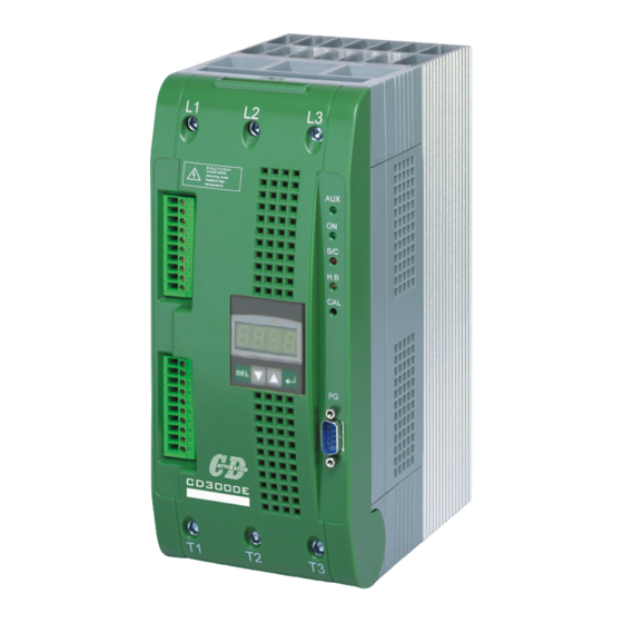
- Page 1 CD3000 -3PH USER’S MANUAL Rev. 02/2015 Thyristor Unit from 25A to 600A 00007 CD Automation S.r.l. Via Picasso 34/36 - 20025 – Legnano (MI) – ITALY Tel +39 0331 577479 – Fax +39 0331 579479 E-Mail: info@cdautomation.com - WEB: www.cdautomation.com...
-
Page 3: Table Of Contents
SUMMARY 1 Important warnings for safety ..................5 2 Introduction ........................ 7 2.1 Advantages compared with analog thyristor unit 2.2 CD-KP 2.3 CD-EASY 2.4 Software Configurator 3 Quick Start ........................ 10 4 CD3000E Sizing ......................11 5 Identification and Order Code ..................12 5.1 Identification of the unit 5.2 Order Code 6 Installation ........................ - Page 4 11 Firing type ....................... 30 11.1 Single Cycle (SC) 11.2 Burst Firing (BF) 11.3 Phase Angle (PA) 11.4 Delay Triggering (DT) 11.5 Action of the Limit Current 11.6 Feed-back type 11.7 Feedback Option 12 Connection description .................... 40 12.1 Access to the Electronic boards 12.2 Supply the Electronic Board 12.3 Analog Inputs 12.4 Analog Outputs...
-
Page 5: Important Warnings For Safety
CD Automation srl CD3000E-3PH from 25A to 500A User’s Manual 1 Important warnings for safety This chapter contains important information for the safety. The not observance of these instructions may result in serious personal injury or death and can cause serious damages to the Thyristor unit and to the components system included. - Page 6 Caution: This icon is present in all the operational procedures where the Improper operation can cause damage for the Thyristor unit. CD Automation reserves the right to modify the own products and this manual without any advise. ®...
-
Page 7: Introduction
CD Automation srl CD3000E-3PH from 25A to 500A User’s Manual 2 Introduction A thyristor unit is semiconductor device which acts as a switch formed by two thyristors in ant parallel. To switch on the alternating current the input signal will be on and the thyristor will switch off at first Zero Crossing voltage with no input signal. -
Page 8: Cd-Kp
User’s Manual 2.2 CD-KP The CD-KP is designed to be connected with all CD Automation's Thyristor units via RS485 communication. On front unit is possible to read the principal operational parameters of the unit like: power, tension, current, reference, alarms, etc. -
Page 9: Software Configurator
CD Automation srl CD3000E-3PH from 25A to 500A User’s Manual 2.4 Software Configurator The software configuration is free and is possible download it from our site: www.cdautomation.com If the Order Code is in line with requirement, then CD3000E has been already configured in Factory and it's ready to use. -
Page 10: Quick Start
CD Automation srl CD3000E-3PH from 25A to 500A User’s Manual 3 Quick Start Caution: this procedure must be performed only by qualified persons. If the Order Code of the Thyristor unit is in line with what you really need, then CD3000E has been already configured in Factory and you just need to do the following steps: 1. -
Page 11: Cd3000E Sizing
CD Automation srl CD3000E-3PH from 25A to 500A User’s Manual 4 CD3000E Sizing 4.1.1 Star wiring with resistive load V = Nominal voltage phase to phase I = Nominal current of the load P = Nominal power of the load 4.1.2 Star wiring with inductive load... -
Page 12: Identification And Order Code
CD Automation srl CD3000E-3PH from 25A to 500A User’s Manual 5 Identification and Order Code 5.1 Identification of the unit Caution: Before to install, make sure that the Thyristor unit have not damages. If the product has a fault, please contact the dealer from which you purchased the product. -
Page 13: Order Code
600A The Max Current must be equal or more than Load Current Load Current Specify this value to configure the unit in CD Automation Load Voltage Specify this value to configure the unit in CD Automation Max Voltage of CD3000E... -
Page 14: Installation
CD Automation srl CD3000E-3PH from 25A to 500A User’s Manual 6 Installation Caution: Don't install near the hot elements or near the units that could give electromagnetic interferences. The CD3000E Thyristor unit must be always mounted in vertical position to improve air cooling on heat- sink. -
Page 15: Dimensions And Fixing Holes
CD Automation srl CD3000E-3PH from 25A to 500A User’s Manual 6.2 Dimensions and Fixing holes 96mm Size S09 (25A÷75A) Weight 5kg 104mm 97mm 12mm Size S11 (100A÷150A) Weight 10,5kg 97mm 222mm 12mm Size S13 (225A) Weight 18kg 222mm 222mm 12mm Size S14 (300A÷600A) -
Page 16: Removing The Cover
CD Automation srl CD3000E-3PH from 25A to 500A User’s Manual 6.3 Removing the cover Size S09 Remove the screw, if present Open the unit Screw Open Size S11 Remove the screw, if present Remove the plastic cover Open the unit... -
Page 17: Wiring Instructions
CD Automation srl CD3000E-3PH from 25A to 500A User’s Manual 7 Wiring instructions Caution: this procedure must be performed only by qualified persons. The Thyristor unit could be susceptible to interferences lost by near equipments or by the power supply,... - Page 18 CD Automation srl CD3000E-3PH from 25A to 500A User’s Manual 7.1.2 Power cable dimensions (suggested) Power Supply Cable Load Cable (Output) Earth Current mm² mm² mm² 25A (S09) 35A (S09) 45A (S09) 75A (S09) 100A (S11) 125A (S11) 150A (S11)
-
Page 19: Power Terminals
CD Automation srl CD3000E-3PH from 25A to 500A User’s Manual 7.2 Power Terminals Warning: Before connecting or disconnecting the unit check that power and control cables are isolated from voltage sources. Terminal Description Line Input Phase 1 Line Input Phase 2... -
Page 20: Command Terminals Size S09
CD Automation srl CD3000E-3PH from 25A to 500A User’s Manual 7.3 Command Terminals Size S09 Warning: Before connecting or disconnecting the unit check that power and control cables are isolated from voltage sources. Terminal Description Voltage Supply for Electronic Boards (See par. 12.2) Voltage Supply for Electronic Boards (See par. -
Page 21: Diagram Of Control Connection Size S09
CD Automation srl CD3000E-3PH from 25A to 500A User’s Manual 7.4 Diagram of control connection Size S09 Caution: this procedure must be performed only by qualified persons. Pot.10K CD-KP 0-10Vdc (option) 4-20mA Input 1 Input 2 RS485 10Vdc 12Vdc TO LOAD NOTE: *1 The user installation must be protecting by electromagnetic circuit breaker or by fuse isolator. -
Page 22: Command Terminals Size
CD Automation srl CD3000E-3PH from 25A to 500A User’s Manual 7.5 Command Terminals Size S11/S13/S14 Warning: Before connecting or disconnecting the unit check that power and control cables are isolated from voltage sources. Terminal Description Internal use Internal use RS485 A RS485 B (See par. -
Page 23: Diagram Of Control Connection Size
CD Automation srl CD3000E-3PH from 25A to 500A User’s Manual 7.6 Diagram of control connection Size S11/S13/S14 Caution: this procedure must be performed only by qualified persons. Pot.10K CD-KP 0-10Vdc (option) 4-20mA Input 1 Input 2 RS485 10Vdc Conf 12Vdc... -
Page 24: Power Output Features
CD Automation srl CD3000E-3PH from 25A to 500A User’s Manual 8 Power output features Voltage Repetitive peak Latching Max peak Leakage T value Frequency Isolation Current Power loss range reverse voltage current one cycle current range Voltage (10msec.) (480V) (600V) -
Page 25: Led Status And Alarms
CD Automation srl CD3000E-3PH from 25A to 500A User’s Manual 9 Led status and Alarms 9.1 LED Status Table On the Electronic board there are LED that indicates the state of the Electronic cards: STATUS DESCRIPTION For All size The power supply is not connected or fault on the electronic board... -
Page 26: Critical Alarms
CD Automation srl CD3000E-3PH from 25A to 500A User’s Manual 9.2 Critical Alarms When a critical alarm is active, it stops the CD3000E thyristor unit and activates the relative digital output (terminal 15). The parameter P001 allows to visualize the state of these alarms (see par. 14.1). -
Page 27: Not Critical Alarm
CD Automation srl CD3000E-3PH from 25A to 500A User’s Manual 9.3 Not Critical Alarm The Not Critical Alarm, doesn’t stop the CD3000E thyristor unit, but is possible to associate an digital output at these alarms (see par. 12.6). The parameter P002 allows to visualize the state of these alarms (see par. 14.1). -
Page 28: Control Panel
CD Automation srl CD3000E-3PH from 25A to 500A User’s Manual 10 Control Panel The Control Panel is placed on the front of the thyristor unit, on his display you can visualize the alarms, the input and output signals and all the configuration parameters (see par. 14). -
Page 29: Scroll The Parameters
CD Automation srl CD3000E-3PH from 25A to 500A User’s Manual 10.1 Scroll the parameters Operator Menu Hardware Menu Setup Menu ... -
Page 30: Firing Type
CD Automation srl CD3000E-3PH from 25A to 500A User’s Manual 11 Firing type Choose an correct firing type allows to optimize the thyristor unit for the installed load. The firing type has already configured in line with customer requirements that are defined in the Order Code. - Page 31 CD Automation srl CD3000E-3PH from 25A to 500A User’s Manual 11.1.1 Suggested recipe for Single Cycle The firing type has already configured in line with customer requirements that are defined in the Order Code. The Order Code is written on the identification label.
-
Page 32: Burst Firing (Bf)
CD Automation srl CD3000E-3PH from 25A to 500A User’s Manual 11.2 Burst Firing (BF) The Burst Firing is similar to the Single Cycle, but consecutive cycles ON are selectable between 2 and 255, with input signal equal at 50%. Burst Firing is a method zero crossing that it reduces the electromagnetic interferences because the thyristor switches at zero voltage crossing. - Page 33 CD Automation srl CD3000E-3PH from 25A to 500A User’s Manual 11.2.2 Suggested recipe for Burst Firing The firing type has already configured in line with customer requirements that are defined in the Order Code. The Order Code is written on the identification label.
-
Page 34: Phase Angle (Pa)
CD Automation srl CD3000E-3PH from 25A to 500A User’s Manual 11.3 Phase Angle (PA) The Phase Angle firing allow the control of the power on the load, for this firing the thyristor can be in conduction only for a part of the voltage cycle. - Page 35 CD Automation srl CD3000E-3PH from 25A to 500A User’s Manual 11.3.2 Suggested recipe for Phase Angle The firing type has already configured in line with customer requirements that are defined in the Order Code. The Order Code is written on the identification label.
-
Page 36: Delay Triggering (Dt)
CD Automation srl CD3000E-3PH from 25A to 500A User’s Manual 11.4 Delay Triggering (DT) The Delay Triggering firing is used the control a primary of transformer coupled with the normal resistances on the secondary (N.B. don't connect cold resistances on the secondary like: Superkanthal, Molybdenum, Platinum, Tungsten, Quartz Lamp). - Page 37 CD Automation srl CD3000E-3PH from 25A to 500A User’s Manual 11.4.1 Suggested recipe for Delay Triggering The firing type has already configured in line with customer requirements that are defined in the Order Code. The Order Code is written on the identification label.
-
Page 38: Action Of The Limit Current
CD Automation srl CD3000E-3PH from 25A to 500A User’s Manual 11.5 Action of the Limit Current The Current Limit is available for each firing type. It control the firing angle of the thyristor to maintain the three RMS current under the set value. -
Page 39: Feed-Back Type
CD Automation srl CD3000E-3PH from 25A to 500A User’s Manual 11.6 Feed-back type The Feed-back type has already configured in line with customer requirements that are defined in the Order Code. The Order Code is written on the identification label. -
Page 40: Connection Description
CD Automation srl CD3000E-3PH from 25A to 500A User’s Manual 12 Connection description 12.1 Access to the Electronic boards To have access to the electronic boards the user must removing the unit’s cover (see par.6.3) Warning: Before operate, be sure that power and control cables are isolated from voltage... -
Page 41: Analog Inputs
CD Automation srl CD3000E-3PH from 25A to 500A User’s Manual 12.3 Analog Inputs The CD3000E thyristor unit has 2 configurable analog inputs (0÷10V, 4÷20mA, ecc): The primary input for the analog setpoint, the secondary input for the Current Profiler or Ext. Feed-Back. - Page 42 CD Automation srl CD3000E-3PH from 25A to 500A User’s Manual 12.3.2 External Current Profiler (Terminals 9 and 7) The secondary input is for the External Current Profiler or for the External Feed-Back. The secondary input is already configured in line with customer requirements that are defined in the Order Code. The Order Code is written on the identification label.
-
Page 43: Analog Outputs
CD Automation srl CD3000E-3PH from 25A to 500A User’s Manual 12.4 Analog Outputs The CD3000E thyristor unit have 1 analog output (0÷10V, 4÷20mA, ecc). The output is for retransmitting the average power on the three phases. 12.4.1 Output 1: Average Power (Terminals 10 and 6 or 10 and 7) The average power output is already configured in line with customer requirements that are defined in the Order Code. -
Page 44: Digital Input
CD Automation srl CD3000E-3PH from 25A to 500A User’s Manual 12.5 Digital Input The CD3000E thyristor unit has 4 digital inputs opto-isolated to 12Vdc. You can activate the inputs with the internal supply (see par. 7.4) or with an external source for example the PLC. -
Page 45: Digital Output
CD Automation srl CD3000E-3PH from 25A to 500A User’s Manual 12.6 Digital Output The CD3000E thyristor unit has 2 digital output (1 for size S09) with relay contact (Max 500mA, 125Vac) and 2 digital output with logic NPN 12Vdc (20ma Max). -
Page 46: Pg Connector
CD Automation srl CD3000E-3PH from 25A to 500A User’s Manual 12.7 PG Connector The PG Connector is used to configure the thyristor unit with the configuration software and with the programming cable. The programming cable is not included. Connettore PG... -
Page 47: Rs485 Serial Port
CD Automation srl CD3000E-3PH from 25A to 500A User’s Manual 12.8 RS485 Serial Port The serial communication port RS485 is available on the Command Terminals and on the 9pin DIN male connector. On this port may be done a network up to 127 CD3000E. -
Page 48: Modbus Communication
CD Automation srl CD3000E-3PH from 25A to 500A User’s Manual 13 MODBUS communication The serial communication port of the thyristor unit is two-wire RS485 type. This port use an half-duplex system. When a Unit must transmit active the transmission line, and when there are not units in transmission the outputs are fixed to high impedance. - Page 49 CD Automation srl CD3000E-3PH from 25A to 500A User’s Manual The following flow-diagram show how to organize the CRC 16 bit. C Language CRC 16 Example static short CRC16 (unsigned char *p_first,unsigned char *p_last) unsigned int crc=0xffff; short j; for (;p_first<=p_last;p_first++) crc ^= *p_first;...
-
Page 50: Read Holding Registers
CD Automation srl CD3000E-3PH from 25A to 500A User’s Manual 13.3 Read Holding Registers This function reads the instantaneous value of only one specified number of parameter from an address. The message is composed by 8 Byte: one Byte is for the address, one for the function (03 Hex), two... -
Page 51: Error And Exception Responses
CD Automation srl CD3000E-3PH from 25A to 500A User’s Manual 13.5 Error and exception responses If a message contains an altered character, if fails the CRC, or if the received message contains a syntax error (for example the number of the byte or of the words is not correct), then the unit will ignore the message. -
Page 52: Configuration Parameters
CD Automation srl CD3000E-3PH from 25A to 500A User’s Manual 14 Configuration Parameters The Configuration Parameters are accessible from the Control Panel (place in front of unit), from the software configurator or through the serial communication port RS485. With the RS485 Serial Port the parameters are not divided by menu, but only by numerical order. - Page 53 CD Automation srl CD3000E-3PH from 25A to 500A User’s Manual P011 (H0B) Voltage supply Function: This parameter read only contains the voltage value of the power supply. P019 (H13) Maximum output Function: This parameter set in % the maximum output voltage.
-
Page 54: Hardware Menu
CD Automation srl CD3000E-3PH from 25A to 500A User’s Manual 14.2 Hardware Menu P057 (H39) Calibration min value of analog input 1 Function: This parameter saves in memory the min value of the primary analog input (see par. 12.3.1) - Page 55 CD Automation srl CD3000E-3PH from 25A to 500A User’s Manual P112 (H70) Digital output configuration (terminal 16) Function: This parameter selects the function of the digital output. Value: 0 = Thyristor Failure 1 = Heater Break Alarm (HB) 2 = Unbalanced Load...
-
Page 56: Setup Menu
CD Automation srl CD3000E-3PH from 25A to 500A User’s Manual 14.3 Setup Menu P023 (H17) Firing Type Function: This parameter selects the Firing Type. Value: 0= BURST firing mode 1= PHASE ANGLE mode 2= DELAY TRIGGERING mode Default: 1 (if not specified in the Order Code) ... - Page 57 CD Automation srl CD3000E-3PH from 25A to 500A User’s Manual P098 (H62) Load Type Value: 0=star 1=star+N 2=delta 3=open delta Default: 0 (if not specified in the Order Code)
-
Page 58: Internal Fuse
CD Automation srl CD3000E-3PH from 25A to 500A User’s Manual 15 Internal Fuse The CD3000E thyristor unit have internal fuse extrarapid at low I²t for the thyristor protection of against the short-circuits. The fuse must have I²t lower than the thyristor one (I²t max) Caution: USE ONLY EXTRARAPID FUSE WITH APPROPRIATE I²... -
Page 59: Maintenance
• 16.4 Warranty condition CD Automation gives a 12 months warranty to its products. The warranty is limited to repairing and parts substitution in our factory and does exclude products not properly used and fuses. Warranty does not include products with serial numbers deleted. The faulty product should be shipped to CD Automation at customer’s cost and our Service will evaluate if product is under warranty terms.
Need help?
Do you have a question about the CD3000 E-3PH and is the answer not in the manual?
Questions and answers