Table of Contents
Advertisement
Advertisement
Table of Contents

Related Manuals for GE pH/C-900


Summary of Contents for GE pH/C-900
- Page 1 Monitor pH/C-900 Operating Instructions Original instructions...
- Page 2 Page intentionally left blank...
-
Page 3: Table Of Contents
Reading pH and conductivity values ................... Setting conductivity scale ......................... Calibrating pH and conductivity ....................5.6.1 Calibrating pH ..........................5.6.2 Calibrating conductivity ......................Using an external chart recorder ....................Storage and shut-down ........................Restart after power failure ....................... Monitor pH/C-900 Operating Instructions 29-0549-25 AB... - Page 4 Instrument housing ..........................Troubleshooting ....................General ..............................Problems and corrective actions ....................Error messages ............................Reference information ..................Menu overview ............................Technical specifications ........................Health and Safety Declaration Form ................... Accessories and spare parts ......................Monitor pH/C-900 Operating Instructions 29-0549-25 AB...
-
Page 5: Introduction
The Operating Instructions provides you with the instructions needed to handle Monitor pH/C-900 in a safe way. Prerequisites In order to operate Monitor pH/C-900 safely, and according to the intended purpose, the following prerequisites must be met: • You should be acquainted with the use of bioprocessing equipment and with the handling of biological materials. - Page 6 If you do, you may be exposed to hazards that can lead to personal injury and you may cause damage to the equipment. Intended use Monitor pH/C-900 is intended for research use only, and shall not be used in any clinical procedures, or for diagnostic purposes. Safety notices This user documentation contains safety notices (WARNING, CAUTION, and NOTICE) concerning the safe use of the product.
-
Page 7: Regulatory Information
Hardware items are identified in the text by bold text (for example, Power). Regulatory information In this section This section describes the directives and standards that are fulfilled by Monitor pH/C-900. Manufacturing information The table below summarizes the required manufacturing information. For further infor- mation, see the EU Declaration of Conformity (DoC) document. - Page 8 • connected to other products recommended or described in the user documentation, • used in the same state as it was delivered from GE, except for alterations described in the user documentation. International standards This product fulfills the requirements of the following standards:...
-
Page 9: User Documentation
Consult the dealer or an experienced radio/TV technician for help. Regulatory compliance of connected equipment Any equipment connected to Monitor pH/C-900 should meet the safety requirements of EN/IEC 61010-1, or relevant harmonized standards. Within EU, connected equipment must be CE marked. - Page 10 1 Introduction 1.4 User documentation The most important documents in the document package with regard to technical aspects of Monitor pH/C-900 are listed below. System-specific documentation User documentation Content Monitor pH/C-900 Operating Detailed system description. Comprehensive user Instructions instructions, method creation, operation, ad- vanced maintenance and troubleshooting.
-
Page 11: Safety Instructions
2.4 Recycling information 2.5 Declaration of Hazardous Substances (DoHS) Safety precautions General precautions Always follow these General precautions to avoid injury when using the Monitor pH/C-900 instrument. WARNING Do not operate the product in any other way than described in the Monitor pH/C-900 Operating Instructions. - Page 12 Follow local and/or national regulations for safe operation and maintenance of Monitor pH/C-900. WARNING Spread of biological agents. The operator has to take all necessary actions to avoid spreading hazardous biological agents.
- Page 13 Maintenance WARNING Electrical shock hazard. All repairs should be done by service personnel authorized by GE. Do not open any covers or replace parts unless specifically stated in the user documentation. Monitor pH/C-900 Operating Instructions 29-0549-25 AB...
- Page 14 For continued protection from fire hazard, replace only with same type and rating of fuse. WARNING Use only GE parts. Only spare parts and accessories that are ap- proved or supplied by GE may be used for maintaining or servicing the product.
-
Page 15: Labels
2 Safety instructions 2.2 Labels Labels Introduction This section describes the system label on Monitor pH/C-900 and its meaning. System label The illustration below shows the system label. Figure 2.1: System Label Note: The specific data shown on the system label below is only an example. Actual data is specific for each individual system and may vary from system to system. -
Page 16: Emergency Procedures
29 of the Code of Federal Regulations (29 CFR), Part 1910.7. Emergency procedures Introduction This section describes how to perform an emergency shutdown of Monitor pH/C-900. The section also describes the result in the event of power failure. Monitor pH/C-900 Operating Instructions 29-0549-25 AB... -
Page 17: Recycling Information
Monitor pH/C-900 shall be decontaminated before decommissioning and all local regu- lations shall be followed with regard to scrapping of the equipment. Disposal, general instructions When taking Monitor pH/C-900 out of service, the different materials must be separated and recycled according to national and local environmental regulations. Recycling of hazardous substances Monitor pH/C-900 contains hazardous substances. - Page 18 Waste of electrical and electronic equipment must not be disposed as unsorted municipal waste and must be collected separately. Please contact an authorized representative of the manufacturer for information concerning the decommissioning of equipment. Monitor pH/C-900 Operating Instructions 29-0549-25 AB...
-
Page 19: Declaration Of Hazardous Substances (Dohs)
Periodic replacement of those consumables or parts to maintain the declared EFUP shall be done in accordance with the Product Maintenance Procedures. This product must not be disposed of as unsorted municipal waste, and must be collected separately and handled properly after decommissioning. Monitor pH/C-900 Operating Instructions 29-0549-25 AB... - Page 20 Indicates that this toxic or hazardous substance contained in at least one of the homoge- neous materials used for this part is above the limit requirement in SJ/T11363-2006. Data listed in the table represents best information available at the time of publication. • Monitor pH/C-900 Operating Instructions 29-0549-25 AB...
-
Page 21: System Description
System description About this chapter This chapter provides a description of Monitor pH/C-900, an on-line monitor for measure- ment of pH and conductivity. The monitor can work with standard glass pH electrodes with a built in liquid-filled reference electrode and BNC connector. -
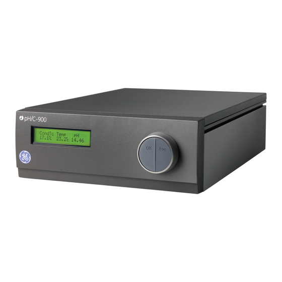
Page 22: Illustrations
3 System description 3.1 Illustrations Illustrations Main unit Figure 3.1: Monitor pH/C-900 with pH electrode and conductivity flow cell Part Function Main unit pH electrode Conductivity flow cell Monitor pH/C-900 Operating Instructions 29-0549-25 AB... - Page 23 Analogue out 0-1V Mains pH Cond Conductivity UniNet -1 Flow Cell Figure 3.2: Backpanel of Monitor pH/c-900, main unit Part Function Conductivity Flow Cell. Connection to conductivity flow cell, 9 pole D-sub connector pH Ground. pH signal ground pH Probe. Connection to pH electrode, standard BNC socket Analog out 0–1V pH.
- Page 24 Figure 3.3: Glass pH electrode Part Function Sealing Internal electrolyte bridge containing 4M KCl saturated with AgCl Silicone sealing Ag/AgCl reference electrode Internal annular coaxial ceramic reference junction External electrolyte bridge containing 1M KNO Monitor pH/C-900 Operating Instructions 29-0549-25 AB...
-
Page 25: Ph Electrode
The monitor controls the AC frequency and increases it with increasing conductivity between 50 Hz and 50 kHz giving maximum linearity and true conductivity values. Figure 3.4: Conductivity flow cell Monitor pH/C-900 Operating Instructions 29-0549-25 AB... -
Page 26: Installation
4 Installation Installation About this chapter This chapter provides required information to enable users and service personnel to unpack, install, move and transport Monitor pH/C-900. Precautions WARNING Before attempting to perform any of the procedures described in this chapter, you must read and understand all contents of the Safety instructions chapter. -
Page 27: Unpacking
To ensure correct ventilation a free space of 0.1 m is required behind and in front of the instrument. Do not use any soft material under the instrument, to ensure that the venti- lation inlet in the front is not blocked. Monitor pH/C-900 Operating Instructions 29-0549-25 AB... -
Page 28: Installing The Conductivity Cell
4 Installation 4.3 Installing the conductivity cell Installing the conductivity cell NOTICE The mains power to Monitor pH/C-900 must be switched off before connecting the instrument to any cells or external equipment. Step Action Place the conductivity cell in a suitable place, for exam- ple on the shelf of the Monitor UV-900 using the clip provided with the UV monitor. -
Page 29: Installing The Ph Electrode
Flow Cell Figure 4.1: Backpanel of Monitor pH/C-900 Installing the pH electrode NOTICE The mains power to Monitor pH/C-900 must be switched off before connecting the instrument to any cells or external equipment. Step Action Hook the flow cell holder on the right hand side of the housing. Secure it with the slide clamp. -
Page 30: Inserting The Ph Electrode
Note: Handle the pH electrode with care. NOTICE The mains power to Monitor pH/C-900 must be switched off before connecting the instrument to any cells or external equipment. NOTICE Never leave the pH electrode in the cell holder when the system is not used, since this might cause the glass membrane of the elec- trode to dry out. -
Page 31: Connecting To Communication Link
PC and a termination plug. The UniNet link connects, in series, the PC with Pump P-900, Monitor pH/C-900, Monitor UV-900 and the Frac-900. The termination plug is connected to the last instrument in the chain. -
Page 32: 4.10 Preparing The Instrument For Use
Before performing these procedures you are recommended to read Section 5.1 Switching on the instrument, on page 34, Moving between menus, on page 34, Return to main menu, on page 36, Select value, on page 36 and Main menu overview, on page 36. Monitor pH/C-900 Operating Instructions 29-0549-25 AB... -
Page 33: Operation
5 Operation Operation About this chapter This chapter provides the information required to safely operate Monitor pH/C-900. Precautions WARNING Before attempting to perform any of the procedures described in this chapter, you must read and understand all contents of the Safety instructions chapter. -
Page 34: Switching On The Instrument
A specific menu is selected by turning the front selection dial clockwise or counterclock- wise. When the required menu is visible the menu or selection is accepted by pressing the OK-button. Action Turn dial clockwise or counterclockwise to select menus. Monitor pH/C-900 Operating Instructions 29-0549-25 AB... - Page 35 Main menu 2 Sub menu 2.1 Sub menu 2 .1.1 Main menu 3 Sub menu 2.2 Main menu 4 Sub menu 2.3.1 Sub menu 2.3 Main menu 5 Sub menu 2.3.2 Figure 5.1: Moving between sub-menus Monitor pH/C-900 Operating Instructions 29-0549-25 AB...
- Page 36 Display Function Main operation menu. The menu is accessed from all Cond Temp position by pressing the ESC button repeatedly. 25.4% 22.9°C 11.50 Alternative display of conductivity with horizontal bar 4.000 mS/cm 22.9°C graph. Monitor pH/C-900 Operating Instructions 29-0549-25 AB...
- Page 37 A check of the conductivity cell and pH electrode can be performed. Step Action Display Select main menu Check, press OK. Select sub menu Check Monitor cell and Electrode, Check Monitor Cell and press OK. Electrode Monitor pH/C-900 Operating Instructions 29-0549-25 AB...
- Page 38 The instrument name and software version are dis- Monitor pH/C-900 played, press OK. V1.00 The date of the last service is displayed, press OK. Date of Maintenance A test of the instrument buzzer is performed, press Buzzer Test Monitor pH/C-900 Operating Instructions 29-0549-25 AB...
- Page 39 (12:26:53) 12: 36:53 after the Alarm/Timer menu. The clock is reset when the power is turned off. A set alarm/timer function can be reset by pressing Alarm/Timer o ? OK in the menu Alarm/Timer off?. OK=o Monitor pH/C-900 Operating Instructions 29-0549-25 AB...
-
Page 40: Setup Menu
°C increase in temperature. If the temperature compensation factor is unknown, a general approximate value of 2% can be set for many common salt buffers. Set the value to 0 for no tem- perature compensation. Monitor pH/C-900 Operating Instructions 29-0549-25 AB... - Page 41 If the dis- played value and the theoretical value correspond, no further action is required. If the values differ, pro- ceed with actions 5–8. Select main menu Setup, press OK. Setup Monitor pH/C-900 Operating Instructions 29-0549-25 AB...
- Page 42 A warning message will be displayed, press OK. Warning! This will change cell calib Enter the theoretical conductivity value according to Setup Adjust Cond the graph, press OK. The new cell constant is auto- (83.53mS/cm) 86.60 matically calculated and updated. Monitor pH/C-900 Operating Instructions 29-0549-25 AB...
- Page 43 Entering the conductivity cell constant After replacing the flow cell, the cell constant has to be set. (The cell constant is shown on the packaging). Step Action Display Select main menu Setup, press OK. Setup Monitor pH/C-900 Operating Instructions 29-0549-25 AB...
- Page 44 Step Action Display Select main menu Setup, press OK. Setup Select menu Setup pH, press OK. Setup pH Monitor pH/C-900 Operating Instructions 29-0549-25 AB...
- Page 45 Place the flow cell together with a precision ther- mometer inside a box or empty beaker to ensure that they are not exposed to draft. Leave them for 15 minutes to let the temperature stabilize. Monitor pH/C-900 Operating Instructions 29-0549-25 AB...
- Page 46 Step Action Display Select main menu Setup, press OK. Setup Select sub menu Setup Temperature, press OK. Setup Temperature Select sub menu Setup Show Temp, press OK. Setup Show Temp (On) On O Monitor pH/C-900 Operating Instructions 29-0549-25 AB...
- Page 47 The unit number is the identification the Monitor pH/C-900 has on the UniNet-bus. It should correspond to the number set in UNICORN for the Monitor pH/C-900. The number should be set to 0 if one pH/C-900 is used. If more than one pH/C-900 monitor is used they must all have different numbers.
-
Page 48: Reading Ph And Conductivity Values
This display shows the actual conductivity value in mS/cm together with the percentage value and as a horizontal bar graph (1) with 10% resolution. If temperature compensation is switched on, Tc is shown in the display. See Figure 5.7 Monitor pH/C-900 Operating Instructions 29-0549-25 AB... -
Page 49: Setting Conductivity Scale
The difference between the value for 100% and 0% value (span) must be at least 1 mS/cm. The settings remain until they are changed. Values above 150% are shown as 150%, values below 0% as 0%. Monitor pH/C-900 Operating Instructions 29-0549-25 AB... -
Page 50: Calibrating Ph And Conductivity
OK. The sub menu Calib pH Buffer 2 is shown. Rinse the electrode tip with distilled water and then immerse the electrode in the 2:nd standard buffer solution (e.g. pH 4.0 or pH 9.0), press OK. Monitor pH/C-900 Operating Instructions 29-0549-25 AB... - Page 51 80%, and no improvement can be achieved by cleaning, it should be replaced. An electrode is still usable at lower slopes and higher asymmetry potentials but the re- sponse will be slower and the accuracy diminish. Monitor pH/C-900 Operating Instructions 29-0549-25 AB...
-
Page 52: Calibrating Conductivity
Set the value, press OK. The zero level is the pH value Set pH Zero Level corresponding to 0 V to the chart recorder. The differ- (pH 2.00) 4.00 ence between zero level and full scale must be at least 1 pH unit. Monitor pH/C-900 Operating Instructions 29-0549-25 AB... -
Page 53: Storage And Shut-Down
If the electrode has dried out, immerse the lower end of the electrode in buffer with a 1:1 mixture of pH 4 buffer and 1 M KNO3 overnight in order to regenate the electrode. Monitor pH/C-900 Operating Instructions 29-0549-25 AB... -
Page 54: Restart After Power Failure
5.9 Restart after power failure Restart after power failure If the power supply to the instrument is interrupted, the instrument automatically restarts itself and displays the main operating window. All set values are retained in the instru- ment. Monitor pH/C-900 Operating Instructions 29-0549-25 AB... -
Page 55: Maintenance
6 Maintenance Maintenance About this chapter This chapter provides required information to enable users and service personnel to clean and maintain the Monitor pH/C-900. The instrument contains no internal user re- placeable parts. Precautions WARNING Before attempting to perform any of the procedures described in this chapter, you must read and understand all contents of the Safety instructions chapter. -
Page 56: Cleaning Before Planned Service
Clean the pH electrode • Cleaning the conductivity cell WARNING Corrosive substance. NaOH is corrosive and therefore dangerous to health. When using hazardous chemicals, avoid spillage and wear protective glasses and other suitable Personal Protective Equipment (PPE). Monitor pH/C-900 Operating Instructions 29-0549-25 AB... -
Page 57: Cleaning The Ph Electrode
Follow local and/or national regulations for safe operation and maintenance of Monitor pH/C-900. Note: The pH electrode has a limited life length and should be replaced every six months or when the response time is slow. -
Page 58: Changing Ph Electrode
Rinse thoroughly with 50 ml de-ionized water. Note: If the flow cell is totally blocked, the blockage can be broken using a thin needle or a piece of string with a diameter less than 0.8 mm. Monitor pH/C-900 Operating Instructions 29-0549-25 AB... -
Page 59: Changing Conductivity Flow Cells
Remove liquid and dirt from the system surface using a cloth, and if necessary, a mild cleaning agent. Do not use strong detergents. Wipe the instrument housing regularly with a damp cloth. Let the instrument dry com- pletely before use. Monitor pH/C-900 Operating Instructions 29-0549-25 AB... -
Page 60: Troubleshooting
GE. Do not open any covers or replace parts unless specifically stated in the user documentation. When contacting GE for support, state the program version of the instrument, which is shown for 2 seconds during switch-on. Problems and corrective actions If the suggested actions do not correct the fault, call GE. - Page 61 Section 6.4 Cleaning the pH electrode, on page 57. If the membrane has dried out, the electrode may • be restored by soaking it in buffer overnight. Clogged liquid junction. Refer to Section 6.4 Cleaning • the pH electrode, on page 57. Monitor pH/C-900 Operating Instructions 29-0549-25 AB...
- Page 62 Mount the dummy electrode instead. Clogged liquid junction. Refer to Section 6.4 Cleaning • the pH electrode, on page 57. pH values vary with varied Replace the pH electrode. back-pressure Monitor pH/C-900 Operating Instructions 29-0549-25 AB...
- Page 63 • ue wrong ing the pH flow cell. Recalibrate the conductivity cell. • Calibration solution, 1.00 M NaCl, not correctly pre- • pared. Prepare a new calibration solution and recal- ibrate the conductivity cell. Monitor pH/C-900 Operating Instructions 29-0549-25 AB...
-
Page 64: Error Messages
If necessary use a flow restrictor after the conductivity flow cell. Error messages If the suggested actions do not correct the fault, contact your local GE representative. Error message Corrective action Cell constant is out of Wrong solution used during calibration. - Page 65 3 Switch on the instrument. Exc x/y in ab.c 1 Switch off the instrument. Exc DIV/O in ab.c 2 Check all connections. Exc instr in ab.c 3 Switch on the instrument. Exc address in ab.c Monitor pH/C-900 Operating Instructions 29-0549-25 AB...
-
Page 66: Reference Information
This chapter contains the following sections: Section See page 8.1 Menu overview 8.2 Technical specifications 8.3 Health and Safety Declaration Form 8.4 Accessories and spare parts Menu overview The illustration below shows the full menu tree of Monitor pH/C-900. Monitor pH/C-900 Operating Instructions 29-0549-25 AB... -
Page 67: Technical Specifications
0 to 14 (specially valid between 2 and 12) Temperature compensated accuracy ±0.1 pH within 4°C to 40°C Non temperature compensated accu- ±0.2 pH within 15°C to 25°C racy ±0.5 pH within 4°C to 15°C and 25°C to 40°C Monitor pH/C-900 Operating Instructions 29-0549-25 AB... - Page 68 84 to 106 kPa (840 to 1060 mbar) atmospheric pressure Flow cells pH cell Max Flow rate 100 ml/min Max Pressure 0.5 MPa (5 bar, 72 psi) Back pressure Max. 0.02 MPa (0.2 bar, 2.9 psi) Internal volume 88 μl Monitor pH/C-900 Operating Instructions 29-0549-25 AB...
- Page 69 (see Section 4.7 Connecting to chart recorder, on page 30 for pin configuration) Display 2 rows with 20 characters each Dimensions, H × W × D 100 × 260 × 370 mm Weight 8.5 kg Noise < 70 dB A Monitor pH/C-900 Operating Instructions 29-0549-25 AB...
-
Page 70: Health And Safety Declaration Form
Bio-Sciences Co rp, 800 Centennial A Avenue, P.O. Box 132 7, Piscataway, NJ 08855-1 1327 © 2010-14 General Electric Com mpany—All rights res served. First publishe ed April 2010. DOC1149542/28-980 00-26 AC 05/2014 Monitor pH/C-900 Operating Instructions 29-0549-25 AB... - Page 71 7, Piscataway, please e call local tec chnical suppo rt or custome service. NJ 08855-1 1327, US © 2010-14 General Electric Com mpany—All rights res served. First publishe ed April 2010. DOC1149544/28-980 00-27 AC 05/2014 Monitor pH/C-900 Operating Instructions 29-0549-25 AB...
-
Page 72: Accessories And Spare Parts
Accessories and spare parts Item Quanti- Code no. ty per pack Monitor pH/C-900 without pH electrode and flow 18-1107-76 cells (Monitor pH/C-900 without pH electrode and flow cells) pH electrode, round tip (pH electrode, round tip) 18-1111-26 pH electrode with flow cell and holder, round tip (pH... - Page 73 FEP tubing, i.d. 0.75 mm, o.d. 1/16" (FEP tubing, i.d. 18-1112-54 0.75 mm, o.d. 1/16") PEEK tubing, i.d. 1.0 mm, o.d. 1/16" (PEEK tubing, i.d. 18-1115-83 1.0 mm, o.d. 1/16") Fingertight connector 1/16" (Fingertight connector 18-1112-55 1/16") Monitor pH/C-900 Operating Instructions 29-0549-25 AB...
- Page 74 Page intentionally left blank...
- Page 75 Page intentionally left blank...
- Page 76 All goods and services are sold subject to the terms and conditions of sale of the company within GE Healthcare which supplies them. A copy of these terms and conditions is available on request. Contact your local GE Healthcare repre- sentative for the most current information.
Need help?
Do you have a question about the pH/C-900 and is the answer not in the manual?
Questions and answers