IBM RS/6000 7043 43P Series Service Manual
Hide thumbs
Also See for RS/6000 7043 43P Series:
- User manual (322 pages) ,
- Supplemental service manual (26 pages) ,
- Setup instructions (16 pages)
Table of Contents
Advertisement
Advertisement
Table of Contents

Related Manuals for IBM RS/6000 7043 43P Series


Summary of Contents for IBM RS/6000 7043 43P Series
- Page 1 RS/6000 7043 43P Series Service Guide SA38-0512-03...
- Page 3 RS/6000 7043 43P Series Service Guide SA38-0512-03...
- Page 4 International Business Machines Corporation 1996, 1998. All rights reserved. Note to U.S. Government Users -- Documentation related to restricted rights -- Use, duplication or disclosure is subject to restrictions set forth is GSA ADP Schedule Contract with IBM Corp.
-
Page 5: Table Of Contents
Contents Communications Statements ......Federal Communications Commission (FCC) Statement ....European Union (EU) Statement viii . - Page 6 MAP 1020: Problem Determination ......MAP 1240: Memory Problem Resolution 2-12 ..... . . MAP 1520: Power 2-15 .
- Page 7 Select Language 7-43 ........Open Firmware Command Line 7-44 .
- Page 8 7043 43P Series Service Guide...
-
Page 9: Communications Statements
Federal Communications Commission (FCC) Statement Note: The IBM 7043 Model 140, Model 150, and Model 240 have been tested and found to comply with the limits for a Class B digital device, pursuant to Part 15 of the FCC Rules. -
Page 10: European Union (Eu) Statement
Responsible Party: International Business Machines Corporation New Orchard Road Armonk, New York 10504 Telephone: (919) 543-2193 Tested to Comply With FCC Standards FOR HOME OR OFFICE USE European Union (EU) Statement This product is in conformity with the protection requirements of EU Council Directive 89/336/EEC on the approximation of the laws of the Member States relating to electromagnetic compatibility. -
Page 11: Avis De Conformité Aux Normes Du Ministère Des Communications Du Canada
Radio Protection for Germany Dieses Gerät ist berechtigt in Übereinstimmung mit dem deutschen EMVG vom 9.Nov.92 das EG–Konformitätszeichen zu führen. Der Aussteller der Konformitätserklärung ist die IBM Germany. Dieses Gerät erfüllt die Bedingungen der EN 55022 Klasse B. Communications Statements... - Page 12 7043 43P Series Service Guide...
-
Page 13: Safety Notices
Safety Notices A danger notice indicates the presence of a hazard that has the potential of causing death or serious personal injury. Danger notices appear on the following pages: 2-15 A caution notice indicates the presence of a hazard that has the potential of causing moderate or minor personal injury. -
Page 14: Laser Safety Information
Laser Safety Information The optical drive in this system unit is a laser product. The optical drive has a label that identifies its classification. The label, located on the drive, is shown below. CLASS 1 LASER PRODUCT LASER KLASSE 1 LUOKAN 1 LASERLAITE APPAREIL A LASER DE CLASSE 1 IEC 825:1984 CENELEC EN 60 825:1991... -
Page 15: Environmental Notices
Recycling facilities may not be available in your area. In the United States, IBM has established a collection process for reuse, recycling, or proper disposal of used sealed lead acid, nickel cadmium and nickel metal hydride batteries and battery packs from IBM equipment. - Page 16 7043 43P Series Service Guide...
-
Page 17: About This Book
This manual is intended to supplement information found in the Diagnostics Information for Multiple Bus Systems. The RS/6000 7043 43P Series Setup Instructions, order number SA38-0510, is a pictorial guide designed to help system users set up their systems. -
Page 18: Trademarks
Trademarks AIX is a registered trademark of International Business Machines Corporation. PowerPC is a trademark of International Business Machines Corporation. 7043 43P Series Service Guide... -
Page 19: Chapter 1. Reference Information
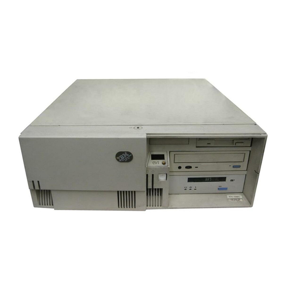
Chapter 1. Reference Information Front View 1 Power Switch: Turns system unit and locks the media bay cover in the power on and off. closed position. 2 Power-On Light: Glows when 8 Diskette-Drive Status Light: system unit is on. Glows when system unit is reading from or writing to a diskette. - Page 20 Rear View Keyboard Port: ( ): For 7 Voltage-Selection Switch (Model keyboard connection. 140 and Model 240 only): Select either 115-V or 230-V setting. Voltage selection is not needed on Model 150 2 Mouse Port ( ): For mouse as it uses an autoranging power supply. connection.
- Page 21 Front View without Covers Chapter 1. Reference Information...
-
Page 22: Specifications (For 7043 Models 140, 150, And 240)
Specifications (for 7043 Models 140, 150, and 240) The mechanical packaging, cooling, power supply, and environmental requirements for the workstation is shown in the following: Dimensions In horizontal orientation – Height - 165 mm (6.5 inches) – Depth - 460 mm (18.1 inches) –... - Page 23 Operating Voltage 100 to 125V ac; 50 to 60 Hz 200 to 240V ac; 50 to 60 Hz Heat Output (Maximum) Operating 796 BTUs per hour Idling 597 BTUs per hour Acoustics Average sound-pressure levels: – At operator position: - 43 dB operating - 38 dB idle –...
-
Page 24: 7043-150 System Features
7043-150 System Features Bus Architecture This section contains information specific to both the 250MHz and 375MHz options for the Model 7043-150. Five 32-bit PCI adapter slots are available: Slots 2 and 3, primary Slots 1, 4, and 5, secondary Microprocessor PowerPC 604e 250 MHz with 1MB parity synchronous L2 cache PowerPC 604e 375 MHz with 1MB parity synchronous L2 cache Memory... - Page 25 Power Supply Autoranging 250 watt, usable with 115 V ac or 230 V ac (Supports Wakeup–on–LAN) Keyboard and Mouse Standard: 101 key Enhanced keyboard Optional: 101/102 or 106 Enhanced Keyboard Standard: 3-button mouse Front-Panel Display 4-digit LED diagnostics display Input/Output Ports 25-pin Parallel 9-pin Serial (2) 8-pin Tablet...
-
Page 26: Setting The Scsi Security Jumpers
Before you begin: Carefully read and follow the safety guidelines detailed in this same section of the RS/6000 7043 43P Series User's Guide, SA38-0511. To increase system unit security, the external SCSI connector can be disabled by changing jumpers inside the system unit. -
Page 27: System Board Locations (For Model 140)
System Board Locations (for Model 140) Chapter 1. Reference Information... - Page 28 Battery connector J38 External SCSI connector Auxiliary 5V connector J39 Riser card connector Audio input connector J41 Operator Panel Connector CD-ROM audio connector J45 Ethernet twisted pair connector CD-ROM audio connector J47 Memory connector A Power connector J48 Memory connector B Power connector J49 Parallel port connector J10 Media Fan connector...
-
Page 29: Model 140 System Board Jumper Settings
Model 140 System Board Jumper Settings For a more complete description of the function of these jumpers, see the system unit User's Guide. Jumper Description Settings Remote power-up Default: Remote power-up disabled. To enable Remote power-up, place jumper on two leftmost pins. Privileged-Access Password Default: disabled. -
Page 30: Riser Card (For Model 140)
Riser Card (for Model 140) Note: The xx digits in the ISA slot location codes are determined by the order in which the ISA adapters are configured. 1-12 7043 43P Series Service Guide... -
Page 31: System Board Locations (For Model 150)
System Board Locations (for Model 150) 1-13 Chapter 1. Reference Information... - Page 32 Battery connector J26 CPU fansink connector Wakeup-on-LAN jumper J27 System fan connector 5x5 Auxiliary 5v connector J28 Memory Connector 2 Audio input connector J30 System fan connector Internal SCSI connector #2 J32 Privileged-Access Password jumper CD-ROM audio connector J33 Internal SCSI 16-bit connector CD-ROM audio connector J35 SCSI security jumper Power connector...
-
Page 33: System Board Jumper Settings (For Model 150)
System Board Jumper Settings (for Model 150) For a more complete description of the function of these jumpers, see the system unit User's Guide. Jumper Description Settings Remote Power-up Default: Remote power-up disabled. To enable Remote power-up, place jumper on the two pins closest to the rear of the system unit. -
Page 34: Riser Card (For Model 150)
Riser Card (for Model 150) 1-16 7043 43P Series Service Guide... -
Page 35: System Board Locations (For Model 240)
System Board Locations (for Model 240) 1-17 Chapter 1. Reference Information... - Page 36 Audio input connector J26 Diskette drive connector Audio output connector J27 Power connectors P1, P2 Microphone jack J28 Power-On Password override jumper (change jumper position to Headphone jack bypass password) External SCSI connector J29 Remote power-up jumper Ethernet twisted pair connector J30 Power connector P9 (aux 5V dc Parallel port connector power connector)
-
Page 37: System Board Jumper Settings (For Model 240)
System Board Jumper Settings (for Model 240) For a more complete description of the function of these jumpers, see the system unit User's Guide. Jumper Description Settings Remote power-up Default: Remote power-up disabled. To enable Remote power-up, place jumper on the two leftmost pins. Privileged-Access Password Default: disabled. -
Page 38: Riser Card (For Model 240)
Riser Card (for Model 240) Note: The xx digits in the ISA slot location codes are determined by the order in which the ISA adapters are configured. Operator panel connector Tablet port connector 1-20 7043 43P Series Service Guide... -
Page 39: Scsi Bus Termination
SCSI Bus Termination The Model 140 and Model 240 have a fast/wide SCSI-2 bus which can support internal and external SCSI devices. However, each controller on these SCSI busses must have a unique SCSI id, and the SCSI busses must be properly terminated both internally and externally (if external devices are used) to ensure SCSI signal integrity. -
Page 40: Service Inspection Guide
Power cables used in other countries consist of the following: Electrical cables, Type HD21. Attachment plugs approved by the appropriate testing organization for the specific countries where they are used. "For units set at 230 V (outside of U.S.): use a cable set consisting of a minimum 18 AWG cable and grounding type attachment plug rated 15 A, 250 V. - Page 41 7. Check for alterations or attachments. If there are any, check for obvious safety hazards such as broken wires, sharp edges, or broken insulation. 8. Check the internal cables for damage. 9. Check for dirt, water, and any other contamination within the system unit. 10.
- Page 42 1-24 7043 43P Series Service Guide...
-
Page 43: Chapter 2. Maintenance Analysis Procedures (Maps)
Chapter 2. Maintenance Analysis Procedures (MAPs) This chapter contains Maintenance Analysis Procedures (MAPs) for the Model 140, Model 150, and Model 240. Entry MAP Notes: 1. When possible, run Online Diagnostics in Service Mode. Online Diagnostics perform additional functions, compared to Standalone Diagnostics. This ensures that the error state of the system is captured in NVRAM for your use in fixing the problem. -
Page 44: Quick Entry Map
Quick Entry MAP Use the following table to determine your starting point in the Entry Map. Quick Entry MAP Table of Contents Problem Description Page No. Service Actions System Stops or Hangs with Alternating Numbers Displayed in the Operator Panel Display System Stops With an Error or Checkpoint Code Displayed There Appears to be a Display Problem (Distortion, Blurring, etc.) Power and Cooling Problems... - Page 45 Symptom Action The system stops and an 8-digit error code Record the error code. If you are working on a starting with the number "2" is displayed. Model 140 or Model 240, go to “Firmware Error Codes” on page 3-4. If you are working on a Model 150, go to “Error Codes”...
- Page 46 Symptom Action All display problems. 1. If using a graphics display: a. Go to the Problem Determination Procedures for the display. b. If you do not locate the problem, replace the display adapter. c. If you do not locate the problem, suspect the systm board.
- Page 47 Symptom Action The system POST indicators are displayed on If you are working on a Model 140 or Model the system console, the system pauses and 240, go to “Fxx Code Boot Problems” on then then restarts. The term "POST indicators" page 3-18.
- Page 48 Symptom Action The SMS configuration list or Boot sequence A device may be set to use the same SCSI bus selection menu shows more SCSI devices ID as the control adapter. Note the ID being attached to a controller/adapter than are actually used by the controller/adapter (this can be attached.
-
Page 49: Map 1020: Problem Determination
MAP 1020: Problem Determination Purpose of This MAP Use this MAP to get an error code if you were not provided one by the customer or you are unable to load diagnostics. If you are able to load the diagnostics, go to MAP 0020 in the Diagnostics Information for Multiple Bus Systems. - Page 50 5. Enter any requested passwords. 6. Wait until the diagnostics are loaded or the system appears to stop. 7. Find your symptom in the following table; then follow the instructions given in the Action column. Symptom Action The disk LED is blinking rapidly, or EIEA, EIEB, The flash EPROM data is corrupted.
- Page 51 Symptom Action The system stops and a 4-digit number Go to “MAP 1540: Minimum Configuration” on beginning with the characters "FF" is displayed page 2-21. in the operator panel display. The system stops and a 4digit number Record the code. Go to “Firmware Checkpoints” beginning with the character "E"...
- Page 52 Step 1020-2 There is a problem with the keyboard. Find the type of keyboard you are using in the following table; then follow the instructions given in the Action column. Keyboard Type Action Type 101 keyboard (U.S.). Identify by the size of Record error code M0KBD001;...
- Page 53 Step 1020-4 1. Turn off, then turn on the system unit. 2. When the keyboard indicator appears, press the F1 key on a directly attached keyboard or the 1 key on an ASCII terminal. 3. When the System Management Services appear, check the error log for any errors.
-
Page 54: Map 1240: Memory Problem Resolution
MAP 1240: Memory Problem Resolution Purpose of This MAP Note: The firmware checkpoint that sent you here could be one of the following: E122, E213, E214, E220 or E3xx. These checkpoints are referred to as "a memory checkpoint" in this MAP. Use this MAP to trouble shoot a problem during the memory test when the system stops at a memory checkpoint and no error code is displayed on the system console. - Page 55 If there is only one memory module installed, go to “Step 1240-3” on page 2-13. If there is more than one memory module installed, go to “Step 1240-2.” Step 1240-2 1. Power off the system. Refer to "Powering Off the System". 2.
- Page 56 Step 1240-4 One of the FRUs remaining in the system unit is defective. 1. Power off the system. Refer to "Powering Off the System". 2. Exchange the following FRUS in the order listed: a. System Board b. Power Supply 3. Power on the system. Refer to "Powering On the System". Does the system stop with a memory checkpoint displayed on the operator panel? Go to "MAP 0410: Repair Checkout"...
-
Page 57: Map 1520: Power
MAP 1520: Power Notes: 1. This is not a start of call MAP. Use this Power MAP only if you have been directed here from a MAP step in the Diagnostics Information for Multiple Bus Systems. 2. The Model 150 has a power LED located on the operator panel. When the system is powered on the LED should be on solid. - Page 58 Step 1520-1 You may be directed to this MAP for several reasons: 1. There is no indication of activity when the power button is pressed. None of the LEDs light and none of the fans, including the fan in the power supply, start to turn.
- Page 59 Step 1520-3 1. Turn the power off. 2. Unplug the system unit power cable from the electrical outlet. 3. Remove external cables (keyboard, mouse, etc.) 4. Remove the top cover. 5. Record the slot numbers of all the installed adapters. Label and record the location of any cables attached to the adapters.
- Page 60 Step 1520-4 Note: Either the power supply, the system board, or the power switch is defective. To test each FRU, exchange the FRUs that have not already been exchanged in the following order. Power supply Power Switch System board (See notes on 2-1.) 1.
- Page 61 Step 1520-5 One of the parts that was removed or unplugged is causing the problem. Install or connect the parts in the following order. 1. Fans 2. Riser card 3. Processor cards (Model 240 only) 4. L2 cache card (Model 140 only) 5.
- Page 62 Does the fan in the power supply turn on and the power LED come on and stay Replace the last part you installed. (If this part was a network adapter, see notes on 2-1.) Repeat these steps until all the parts have been installed. If the symptom did not change and all the parts have been replaced, call your service support person for assistance.
-
Page 63: Map 1540: Minimum Configuration
MAP 1540: Minimum Configuration Note: If you were sent to this MAP from the Diagnostics Information for Multiple Bus Systems as a result of an SRN 101-xxx problem, go to “Fxx Code Boot Problems” on page 3-18 and follow the instructions there before using the MAP 1540 steps. -
Page 64: Map 1540A: Minimum Configuration (For The Model 140 And Model 150)
MAP 1540A: Minimum Configuration (for the Model 140 and Model 150) Step 1540A-1 1. Ensure that the diagnostics and the operating system are shut down. 2. Turn the power off. 3. Turn the power on. 4. Insert the diagnostic CD-ROM into the CD-ROM drive. 5. - Page 65 Step 1540A-2 1. Turn the power off. 2. Disconnect all external cables. 3. Remove the top cover. 4. Record the slot numbers of any adapter cards installed in the system unit. Label and record the location of any cables attached to the adapters. Remove all the adapters from the system unit.
- Page 66 Step 1540A-3 One of the FRUs remaining in the system unit is defective. 1. Turn the power off. 2. Exchange one of the FRUs in the following list. a. System board (See notes on 2-1.) b. Riser card c. Memory module 3.
- Page 67 Step 1540A-4 No failure was detected with this configuration. 1. Turn the power off. 2. Install a memory module. 3. Turn the power on. Does the operator panel do one of the following: Stop with any code other than – FDC, FF2, FF3, or F4D (Model 140) –...
- Page 68 Step 1540A-5 The failure may be caused by the last memory module installed. To isolate the failing FRU, do the following: 1. Turn the power off. 2. Exchange the last memory module installed. 3. Turn the power on. Does the operator panel do one of the following: Stop with any code other than –...
- Page 69 Step 1540A-6 One of the FRUs remaining in the system unit is defective. 1. Turn the power off. 2. Exchange one of the FRUs in the following list. System board (See notes on 2-1.) Power supply. 3. Turn the power on. Does the operator panel do one of the following: Stop with any code other than –...
- Page 70 Step 1540A-7 (Model 140 only) 1. Turn the power off. 2. Install the L2 cache card. Does the operator panel do one of the following: Stop with any code other than – FDC, FF2, FF3, or F4D (Model 140) Alternate between –...
- Page 71 Step 1540A-8 1. Turn the power off. 2. Reconnect the system console. Notes: a. If an ASCII terminal has been defined as the system console, attach the ASCII terminal cable to the S1 connector on the rear of the system unit. Also connect the internal serial and Ethernet cables to the system board.
- Page 72 Is the SMS screen displayed? One of the FRUs remaining in the system unit is defective. In the following order, exchange the FRUs that have not been exchanged: 1. Go to the Problem Determination Procedures (test procedures) for the device attached to the S1 serial port or the display attached to the graphics adapter, and test those devices.
- Page 73 Step 1540A-9 1. Make sure the diagnostic CD-ROM is inserted into the CD-ROM drive. 2. Turn the power off. 3. Plug the SCSI cable into the SCSI connector on the system board. 4. Disconnect the signal and power connectors from all the SCSI devices except the CD-ROM drive.
- Page 74 Repeat this step, adding one SCSI device at a time, until all the SCSI devices that were attached to the integrated SCSI adapter are connected and tested. Go to “Step 1540A-10.” Step 1540A-10 The system is working correctly with this configuration. One of the FRUs (adapters) that you removed is probably defective.
- Page 75 Step 1540A-11 The system is working correctly with this configuration. One of the FRUs (adapters) that you removed is probably defective, 1. Turn the power off. 2. Install a FRU (adapter) and connect any cables and devices, if any, that were attached to it.
- Page 76 Step 1540A-12 1. Make sure the diagnostic CD-ROM disc is inserted into the CD-ROM drive. 2. Turn the power off. 3. Starting with the last installed adapter, if there are any devices and cables attached to it, disconnect one attached device and cable. 4.
- Page 77 Step 1540A-13 1. Follow the instructions on the screen to select the system console. 2. When the DIAGNOSTIC OPERATING INSTRUCTIONS screen is displayed, press Enter. 3. If the terminal type has not been defined, you must use the Initial Terminal option on the FUNCTION SELECTION menu to initialize the AIX operating system environment before you can continue with the diagnostics.
- Page 78 Step 1540A-14 Look at the FRU part numbers associated with the SRN. Have you exchanged all the FRUs that correspond to the failing function codes? Exchange the FRU with the highest failure percentage that has not been changed. Repeat this step until all the FRUs associated with the SRN have been exchanged or diagnostics run with no trouble found.
- Page 79 Step 1540A-15 Does the system have adapters or devices that require supplemental media? Go to “Step 1540A-16.” Go to “Step 1540A-17.” Step 1540A-16 Consult the PCI adapter configuration documentation for your operating system to verify that all installed adapters are configured correctly. Go to "MAP 0410: Repair Checkout"...
- Page 80 Step 1540A-18 The adapter or device is probably defective. If the supplemental media is for an adapter replace the FRUs in the following order: 1. Adapter 2. Riser card 3. System board. If the supplemental media is for a device replace the FRUs in the following order: 1.
-
Page 81: Map 1540B: Minimum Configuration (For The Model 240)
MAP 1540B: Minimum Configuration (for the Model 240) Step 1540B-1 1. Ensure that the diagnostics and the operating system are shut down. 2. Insert the diagnostic CD-ROM into the CD-ROM drive. 3. Turn the power off. 4. Turn the power on. 5. - Page 82 Step 1540B-2 1. Turn the power off. 2. Disconnect all external cables. 3. Remove the top cover. 4. Record the slot numbers of the ISA and PCI adapters. Label and record the location of any cables attached to the adapters. Remove all the adapters. 5.
- Page 83 Step 1540B-3 One of the FRUs remaining in the system unit is defective. If the following steps call for a system board to be replaced, see notes on page 2-1. 1. If the disk LED is on, turn the power off and exchange the following FRUs in order: a.
- Page 84 Step 1540B-4 No failure was detected with this configuration. 1. Turn the power off. 2. Install a pair memory modules. 3. Turn the power on. Does the operator panel stabilize for more than 60 seconds with code FDC, FF2, FF3, or F4D displayed, or is one of these codes displayed immediately before the system unit attempts to restart? Go to “Step 1540B-5.”...
- Page 85 Step 1540B-6 One of the FRUs remaining in the system unit is defective. 1. Turn the power off. 2. Exchange the following FRUs the order listed. a. System board (See notes on page 2-1) b. Power supply 3. Turn the power on. Does the operator panel stabilize for more than 60 seconds with code FDC, FF2, FF3, or F4D displayed, or is one of these codes displayed immediately before the system unit attempts to restart?
- Page 86 Step 1540B-7 1. Turn the power off. 2. Reconnect the system console. Notes: a. If an ASCII terminal has been defined as the system console, attach the ASCII terminal cable to the S1 connector on the rear of the system unit. Also connect the internal serial and Ethernet cables to the system board.
- Page 87 Is the SMS screen displayed? One of the FRUs remaining in the system unit is defective. In the following order, exchange the FRUs that have not been exchanged: 1. Go to the Problem Determination Procedures (test procedures) for the device attached to the S1 serial port or the display attached to the graphics adapter, and test those devices.
- Page 88 Step 1540B-8 1. Make sure the diagnostic CD-ROM is inserted into the CD-ROM drive. 2. Turn the power off. 3. Plug the internal SCSI cable into both SCSI connectors on the system board. 4. Disconnect the signal and power connectors from all the SCSI devices except the CD-ROM drive.
- Page 89 Repeat this step, adding one SCSI device at a time, until all the SCSI devices that were attached to the integrated SCSI adapter are connected and tested. Go to “Step 1540B-9.” Step 1540B-9 The system is working correctly with this configuration. One of the FRUs (adapters) that you removed is probably defective.
- Page 90 Step 1540B-10 The system is working correctly with this configuration. One of the FRUs (adapters) that you removed is probably defective. 1. Turn the power off. 2. Install the second processor card if one was removed. If a second processor was not removed, or has already been reinstalled and verified, install a FRU (adapter) and connect any cables and devices that were attached to it.
- Page 91 Step 1540B-11 The last FRU installed or one of its attached devices is probably defective. 1. Make sure the diagnostic CD-ROM disc is inserted into the CD-ROM drive. 2. Turn the power off. 3. Starting with the last installed adapter, disconnect one attached device and cable.
- Page 92 Step 1540B-12 1. Follow the instructions on the screen to select the system console. 2. When the DIAGNOSTIC OPERATING INSTRUCTIONS screen is displayed, press Enter. 3. If the terminal type has not been defined, you must use the Initial Terminal option on the FUNCTION SELECTION menu to initialize the AIX operating system environment before you can continue with the diagnostics.
- Page 93 Step 1540B-13 Look at the FRU part numbers associated with the SRN. Have you exchanged all the FRUs that correspond to the failing function codes? Exchange the FRU with the highest failure percentage that has not been changed. Repeat this step until all the FRUs associated with the SRN have been exchanged or diagnostics run with no trouble found.
- Page 94 Step 1540B-15 Consult the ISA and PCI adapter configuration documentation for your operating system to verify that all installed adapters are configured correctly. Go to "MAP 0410: Repair Checkout" in the Diagnostics Information for Multiple Bus Systems. If the symptom did not change and all the FRUs have been exchanged, call your service support person for assistance.
- Page 95 Step 1540B-17 The adapter or device is probably defective. If the supplemental media is for an adapter replace the FRUs in the following order: 1. Adapter. 2. Riser card 3. System board If the supplemental media is for a device replace the FRUs in the following order: 1.
- Page 96 2-54 7043 43P Series Service Guide...
-
Page 97: Chapter 3. Error Code To Fru Index For The Model 140 And Model
Chapter 3. Error Code to FRU Index for the Model 140 and Model 240 Note: For Error Code and Checkpoint information for the Model 150, see Chapter 4, “Error Code to FRU Index for the Model 150” on page 4-1. The Error Code to FRU Index lists error symptoms and possible causes. -
Page 98: Post Error Codes
POST Error Codes Table 3-1 (Page 1 of 2). POST Error Codes Error Code Description Action/ Possible Failing FRU M0CON000 The system hung during POST. Go to “MAP 1540: Minimum Configuration” on page 2-21. M0CPU000 The CPU POST failed. 1. CPU Card (Model 240) 2. - Page 99 Table 3-1 (Page 2 of 2). POST Error Codes Error Code Description Action/ Possible Failing FRU M0SCSI00 Unable to load diagnostics. Go to “MAP 1540: Minimum Configuration” on page 2-21. M0SCSI01 Unable to load diagnostics. Go to “MAP 1540: Minimum Configuration”...
-
Page 100: Firmware Error Codes
Firmware Error Codes If you replace FRUs and the problem is still not corrected, go to MAP 0030 in the Diagnostics Information for Multiple Bus Systems unless otherwise indicated in the tables. Table 3-2 (Page 1 of 9). Firmware Error Codes. Error Code Description Action/... - Page 101 Table 3-2 (Page 2 of 9). Firmware Error Codes. Error Code Description Action/ Possible Failing FRU Power on Password must be set for Unattended mode requires the setting Unattended mode of the Power On password before can be enabled. Battery drained or needs replacement 1.
- Page 102 Table 3-2 (Page 3 of 9). Firmware Error Codes. Error Code Description Action/ Possible Failing FRU SMS: Invalid RIPL IP address Enter valid RIPL IP address. Example: 000.000.000.000 SMS: Invalid portion of RIPL IP Enter valid RIPL IP address. address (>255) Example: 255.192.002.000 SMS: No SCSI controllers present The system board should always have...
- Page 103 Table 3-2 (Page 4 of 9). Firmware Error Codes. Error Code Description Action/ Possible Failing FRU Test Unit Ready Failed - sense data 1. Media (Removable media devices) available 2. SCSI device Send Diagnostic Failed 1. SCSI device Send Diagnostic Failed - DevOfl cmd 1.
- Page 104 Table 3-2 (Page 5 of 9). Firmware Error Codes. Error Code Description Action/ Possible Failing FRU Flash write protected. 1. Turn off, turn on system unit, retry. 2. Replace system board. (See notes on page 3-1.) 25A0xxy0 Cache: L2 controller failure Refer to error code 2B2xxyrr for a description of the “xx”...
- Page 105 Table 3-2 (Page 6 of 9). Firmware Error Codes. Error Code Description Action/ Possible Failing FRU xxx=000 Initialization failed, device test failed init-nvram invoked, ALL of NVRAM initialized init-nvram invoked, GE area preserved, remaining areas initialized. Data corruption detected, ALL of NVRAM initialized Data corruption detected, GE area preserved, remaining areas initialized...
- Page 106 Table 3-2 (Page 7 of 9). Firmware Error Codes. Error Code Description Action/ Possible Failing FRU xxx=001 DIMM fails memory test. For more information: 1. Use the location code obtained from the SMS Error Log utility (described in “Step 1020-4” on page 2-11) to identify which DIMM is defective.
- Page 107 Table 3-2 (Page 8 of 9). Firmware Error Codes. Error Code Description Action/ Possible Failing FRU xxx=001 RTC not updating RTC initialization required Bad time/date values Set Time/Date 29000002 Keyboard/Mouse controller failed Replace system board. (See notes on self-test page 3-1.) 29A00003 Keyboard not present/detected 1.
- Page 108 Table 3-2 (Page 9 of 9). Firmware Error Codes. Error Code Description Action/ Possible Failing FRU rr = 22 Bad Processor/CPU 1. Processor (card) 2. System board (See notes on page 3-1.) Disabled due to Asymetrical MP configuration (Model 240) 1.
- Page 109 Memory PD Bits The following table expands the firmware error code 25Cyyxxx on page 3-10, where yy is the PD values in the table below. Use these values to identify the type of memory that generated the error. If you replace FRUs and the problem is still not corrected, go to MAP 0030 in the Diagnostics Information for Multiple Bus Systems unless otherwise indicated in the tables.
-
Page 110: Firmware Checkpoints
Firmware Checkpoints The following Fxx code checkpoints are displayed on the operator panel during system startup, and can be used for diagnostic purposes. If you replace FRUs and the problem is still not corrected, go to MAP 0030 in the Diagnostics Information for Multiple Bus Systems unless otherwise indicated in the tables. - Page 111 Table 3-4 (Page 2 of 5). Firmware Checkpoints. Checkpoint Description Action/ Possible Failing FRU Probing PCI bridge secondary bus 1. PCI Adapters 2. Riser card 3. System board. If a network adapter or system board is replaced, see 3-1. Transferring control to Operating See “Fxx Code Boot Problems”...
- Page 112 Table 3-4 (Page 3 of 5). Firmware Checkpoints. Checkpoint Description Action/ Possible Failing FRU BootP request Refer to “Fxx Code Boot Problems” on page 3-18 for general considerations. 1. Turn off then on, and retry the boot operation. 2. Verify the network connection (network could be down).
- Page 113 Table 3-4 (Page 4 of 5). Firmware Checkpoints. Checkpoint Description Action/ Possible Failing FRU Firmware flash corrupted, load from Ensure that the diskette installed diskette. contains recovery image appropriate for this system unit. The System Management Services recovery procedure for the flash EEPROM should be executed.
- Page 114 Table 3-4 (Page 5 of 5). Firmware Checkpoints. Checkpoint Description Action/ Possible Failing FRU SCSI bus initialization 1. Verify proper SCSI bus termination. 2. Verify that there are no ID conflicts among SCSI devices. 3. Verifiy that the system board SCSI security jumpers are set properly, if external devices are attached to the system board...
- Page 115 If the intended boot device is not correctly specified in the boot sequence, add it to the boot sequence using the SMS menus. If the intended boot device cannot be added to the boot sequence, go to step 3. If you are attempting to boot from the network, go to step 2. If you are attempting to boot from a disk drive or CD-ROM, go to step 3.
- Page 116 f. Replace network cable g. Replace network adapter (unless trying to boot using the ethernet controller on the system board) h. It is possible that another installed adapter is causing the problem. Remove all installed adapters except the one you are trying to boot, and try to boot the standalone diagnostics from a CDROM drive attached to the scsi controller on the system board.
-
Page 117: Firmware Location Codes
Firmware Location Codes These codes can be found in the System Management Services error log as described in “Step 1020-4” on page 2-11. Location codes vary in length depending on the device being referenced. In general, if a location code is referring to an adapter or controller, the location code is 4 digits (eg. - Page 118 Note: The values used in the examples are representative of the format and relationships described above. 00-00 System board 00-00-00-01 Memory SIMM/DIMM in socket 1 01-A0 ISA bus Primary IDE controller 01-C0 ISA bus Diskette Controller 01-C0-00-01 2nd ISA bus Diskette drive 00-00 2nd ISA bus Serial Port (SRN value differentiates between 1st and 2nd) 04-01...
-
Page 119: Chapter 4. Error Code To Fru Index For The Model 150
Chapter 4. Error Code to FRU Index for the Model 150 Note: This chapter contains error code and checkpoint information for the Model 150 only. For information on the Model 140 and Model 240, refer to Chapter 3, “Error Code to FRU Index for the Model 140 and Model 240” on page 3-1. - Page 120 Table 4-1 (Page 2 of 11). Firmware Error Codes Error Code Function / Repair Action/Possible Failing FRU Description 20D0000F Selftest failed on Check the SMS error log entry for this error code. The device, no location code (if present) in the error log entry should error/location code identify the location of the failing device.
- Page 121 Table 4-1 (Page 3 of 11). Firmware Error Codes Error Code Function / Repair Action/Possible Failing FRU Description 20E0000C EEPROM read 1. Power Off/On machine problem 2. Replace System Planar 20E00017 Cold boot needed Power Off/On machine for password entry Informational 20EE0003 IP parameter...
- Page 122 Table 4-1 (Page 4 of 11). Firmware Error Codes Error Code Function / Repair Action/Possible Failing FRU Description 20EE000A Pointer to Operating Values normally found in non-volatile storage that point System not found in to the location of an Operating System were not found. non-volatile storage This can happen for two reasons, either your installed Operating System doesn't support storing the values or...
- Page 123 Table 4-1 (Page 5 of 11). Firmware Error Codes Error Code Function / Repair Action/Possible Failing FRU Description 21A00001 Test Unit Ready Refer to SCSI device error notes above Failed - hardware 1. Replace SCSI device error 2. Replace SCSI cable 3.
- Page 124 Table 4-1 (Page 6 of 11). Firmware Error Codes Error Code Function / Repair Action/Possible Failing FRU Description 25010000 No diskette in drive Insert diskette containing firmware update file 25010001 Diskette seek error 1. Retry function. 2. Replace diskette drive 3.
- Page 125 Table 4-1 (Page 7 of 11). Firmware Error Codes Error Code Function / Repair Action/Possible Failing FRU Description 25A80002 init-nvram invoked, Refer to NVRAM problem resolution above some data partitions may have been preserved 25A80011 Data corruption Refer to NVRAM problem resolution above detected, ALL of NVRAM initialized 25A80012...
- Page 126 Table 4-1 (Page 8 of 11). Firmware Error Codes Error Code Function / Repair Action/Possible Failing FRU Description 25A80998 NVRAMRC script Execution of a command line within the nvram evaluation error - configuration variable “nvramrc” (script) resulted in a command line “throw”...
- Page 127 Table 4-1 (Page 9 of 11). Firmware Error Codes Error Code Function / Repair Action/Possible Failing FRU Description 25AA0007 Unable to lock Refer to EEPROM problem resolution above eeprom Memory errors Use the location code obtained from the SMS Error Log utility (described in Map Step 1020-4) to identify which memory DIMM the error is reported against.
- Page 128 Table 4-1 (Page 10 of 11). Firmware Error Codes Error Code Function / Repair Action/Possible Failing FRU Description 26020006 PCI adapter 1. Update card firmware firmware failed 2. Move card to another slot evaluation (has a 3. Run AIX adapter diagnostics bug) 4.
-
Page 129: Bus Srn To Fru Reference Table
Table 4-1 (Page 11 of 11). Firmware Error Codes Error Code Function / Repair Action/Possible Failing FRU Description 28A00040 Fan failure Check on the following: Ensure fans are properly connected to the I/O planar Reseat all suspected fan(s) connectors Look for obstructions that may prevent the fans from normal operations. - Page 130 Table 4-2 (Page 1 of 2). Bus SRN to FRU Reference Table Possible Failing Device and AIX Associated Identification Location Code 9CC-100 PCI Bus 00 Internal SCSI port 1 (10-60) I/O board. (See note at the bottom of this table.) Internal/External SCSI port 2 (30-58) I/O board.
- Page 131 Table 4-2 (Page 2 of 2). Bus SRN to FRU Reference Table Possible Failing Device and AIX Associated Identification Location Code Tablet port/device (01-FF) I/O board. (See note at the bottom of this table.) Note: If a network adapter, or the I/O board is replaced, the network administrator must be notified so that the client IP addresses used by the server can be changed.
-
Page 132: Firmware Checkpoints
Memory PD Bits The following table expands the firmware error code 25Cyyrrr on page 4-9, where yy is the PD values in the table below. Use these values to identify the type of memory that generated the error. If you replace FRUs and the problem is still not corrected, go to MAP 0030 in the Diagnostics Information for Multiple Bus Systems unless otherwise indicated in the tables. - Page 133 Table 4-3 (Page 2 of 13). Firmware Checkpoints Checkpoint Description Repair Action (hex) E109 Copy CRC See “Unresolved problems” on page 4-27 verification code to E10A Turn on cache See “Unresolved problems” on page 4-27 E10B Flush cache See “Unresolved problems” on page 4-27 E10C Jump to CRC See “Unresolved problems”...
- Page 134 Table 4-3 (Page 3 of 13). Firmware Checkpoints Checkpoint Description Repair Action (hex) E119 Initialize base See “Unresolved problems” on page 4-27 memory, stack E11A Copy uncompressed See “Unresolved problems” on page 4-27 recovery block code to RAM E11B Jump to code in See “Unresolved problems”...
- Page 135 Table 4-3 (Page 4 of 13). Firmware Checkpoints Checkpoint Description Repair Action (hex) E12B Set MP operational See “Unresolved problems” on page 4-27 parameters (eg. L.E.?, Real?) E12C Set MP CPU node See “Unresolved problems” on page 4-27 characteristics E12D Park secondary See “Unresolved problems”...
- Page 136 Table 4-3 (Page 5 of 13). Firmware Checkpoints Checkpoint Description Repair Action (hex) E14C Create See “Unresolved problems” on page 4-27 terminal-emulator node E14D Load boot image See “Boot Problems/Concerns” on page 4-28 E14E Create Client See “Unresolved problems” on page 4-27 Interface node/dictionary E14F...
- Page 137 Table 4-3 (Page 6 of 13). Firmware Checkpoints Checkpoint Description Repair Action (hex) E15F Adapter VPD probe See “Unresolved problems” on page 4-27 E160 CPU Node VPD See “Unresolved problems” on page 4-27 Creation E161 ROOT Node VPD See “Unresolved problems” on page 4-27 Creation E162 SP Node VPD...
- Page 138 Table 4-3 (Page 7 of 13). Firmware Checkpoints Checkpoint Description Repair Action (hex) E180 SP Command setup See “Unresolved problems” on page 4-27 E183 SP Post See “Unresolved problems” on page 4-27 E190 Create ISA node See “Unresolved problems” on page 4-27 E193 Initialize Super I/O See “Unresolved problems”...
- Page 139 Table 4-3 (Page 8 of 13). Firmware Checkpoints Checkpoint Description Repair Action (hex) E1BD Probe for (ISA) Replace System Planar mouse See “Unresolved problems” on page 4-27 E1BE Create op-panel See “Unresolved problems” on page 4-27 node E1BF Create pwr-mgmt See “Unresolved problems”...
- Page 140 Table 4-3 (Page 9 of 13). Firmware Checkpoints Checkpoint Description Repair Action (hex) E1DC Dynamic console If a console is attached but nothing is displayed on it, selection follow the steps associated with “All display problems” in the Entry MAP tables. If selection screen(s) can be seen on the terminals and the appropriate key on the input device associated with the desired display or terminal is pressed, within...
- Page 141 Table 4-3 (Page 10 of 13). Firmware Checkpoints Checkpoint Description Repair Action (hex) E1E4 Initialize Super I/O See “Unresolved problems” on page 4-27 with default values E1E5 XCOFF boot image See “Unresolved problems” on page 4-27 initialization E1E6 Set up early See “Unresolved problems”...
- Page 142 Table 4-3 (Page 11 of 13). Firmware Checkpoints Checkpoint Description Repair Action (hex) E1EE Jump to composite See “Unresolved problems” on page 4-27 image E1EF Erase flash See “Unresolved problems” on page 4-27 E1F0 Start O.B.E. See “Unresolved problems” on page 4-27 E1F1 Begin selftest See “Unresolved problems”...
- Page 143 Table 4-3 (Page 12 of 13). Firmware Checkpoints Checkpoint Description Repair Action (hex) E206 Look for PRISM on 1. Replace System Planar PCG and switch to 50MHz E207 Setup Data gather 1. Replace System Planar mode and 64/32-bit mode on PCG E208 Assign bus number 1.
- Page 144 Table 4-3 (Page 13 of 13). Firmware Checkpoints Checkpoint Description Repair Action (hex) E243 Set up Grackle 1. Replace System Planar configuration registers E244 Enable system 1. Replace System Planar speaker and send a beep E246 System firmware 1. Replace System Planar corrupted, take recover path E247...
- Page 145 Unresolved problems: Go to MAP 1540A or 1540B for any of the following conditions: A 4-digit code in the range of “E100” through “EFFF” is displayed on the operator panel display but is not listed in Table 4-3 on page 4-14. A 4-digit code is displayed and is listed in Table 4-3 on page 4-14, but there are no repair actions or FRUs listed for the code.
-
Page 146: Boot Problems/Concerns
Boot Problems/Concerns Depending on the boot device, a checkpoint may be displayed on the operator panel for an extended period of time while the boot image is retrieved from the device. This is particularly true tape and network boot attempts. If booting from CDROM or tape, watch for activity on the drive's LED indicator. - Page 147 If the diagnostics are successful, it may be necessary to perform an operating system specific recovery process, or reinstall the operating system. If unable to load standalone diagnostics: a. Verify proper SCSI bus termination. b. Check SCSI cabling. c. It is possible that another attached SCSI device is causing the problem. Disconnect the signal and power cables from any other SCSI devices attached to the SCSI adapter that the CD-ROM drive is attached to.
- Page 148 Go to "MAP 0410: Repair Checkout" in the Diagnostics Information for Multiple Bus Systems. 4-30 7043 43P Series Service Guide...
-
Page 149: Chapter 5. Location Codes (Model 150 Only)
Chapter 5. Location Codes (Model 150 only) This system unit uses physical location codes in conjunction with AIX location codes to provide mapping of the failing field replaceable units. The location codes are produced by the system unit's firmware and AIX. Physical Location Codes Physical location codes provide a mapping of logical functions in a platform (or expansion sites for logical functions, such as connectors or ports) to their specific... - Page 150 Specifically, the format of a location code is defined as follows: pn[.n][- or /]pn[.n][- or /]... Where p is a defined alpha location type prefix, n is a location instance number, and [.n] is a sub-location instance number (where applicable). Sub-location notation is used only for location types which have clearly defined and limited expansion sites;...
- Page 151 Name Location Physical Logical Location Code Connection Identification Code Keyboard Port 01-K1-00 P1/K1 Base Address 0x0060 Mouse Port 01-K1-01 P1/O1 Base Address 0x0060 Serial Port 1 01-S1 P1/S1 Base Address 0x03F8 Serial Port 2 01-S2 P1/S2 Base Address 0x02F8 Parallel Port 01-R1 P1/R1 Base Address...
-
Page 152: Aix Location Codes
For PCI adapters where x is equal to or greater than 1. The x and y are characters in the range of 0-9, A-H, J-N, P-Z (O, I, and lower case are omitted) and are equal to the parent bus's ibm, aix-loc Open Firmware Property. The possible values for CD depend on the adapter/card. - Page 153 of 0-9, and A-F (hex numbers). This allows the location code to uniquely identify multiple adapters on individual PCI cards. For pluggable ISA adapters, CD is equal to the order the ISA cards defined/configured either by SMIT or the ISA Adapter Configuration Service Aid. For integrated ISA adapters, CD is equal to a unique code identifying the ISA adapter.
- Page 154 7043 43P Series Service Guide...
-
Page 155: Chapter 6. Loading The System Diagnostics
Chapter 6. Loading the System Diagnostics If no keys are pressed after the system unit power is turned on, the system unit searches a list of devices (the default boot list) for a bootable image. If a bootable image is found, then the system unit loads and starts the operating system. This is called a normal boot. -
Page 156: Service Mode Boot: Loading Diagnostics
to Chapter 7, “System Management Services” on page 7-1 for more information on custom boot lists. If no bootable image is found in the custom boot list, then the system restarts and attempts to boot again. If the custom boot list is discovered to be corrupted, the system rebuilds the custom boot list according to the default boot list. - Page 157 Booting in Service Mode from the Custom Boot List To boot in service mode from the custom boot list, do the following: 1. Verify with the system administrator and users that all programs are to be stopped, then do so. 2.
-
Page 158: Standalone Vs. Online Diagnostics
Standalone vs. Online Diagnostics When the system unit attempts to boot in service mode (from either the default or custom boot list) and locates a diagnostics CD-ROM before any other bootable image, then the system unit starts standalone diagnostics. Standalone diagnostics can be used on system units installed with any supported operating system. - Page 159 Summary: Boot Options and Control Keys The following keys can be pressed when the keyboard POST indicator appears. Result F1 (display keyboard) Normal mode boot, graphical System Management Services starts. 1 (ASCII keyboard) Normal mode boot, text-based System Management Services starts. F5 (display keyboard) Service mode boot, default boot list.
- Page 160 7043 43P Series Service Guide...
-
Page 161: Chapter 7. System Management Services
Chapter 7. System Management Services The System Management Services make it possible for you to view information about your computer and to perform such tasks as setting passwords and changing device configurations. If you have chosen a graphical display as your system console, you can use the graphical System Management Services described below. - Page 162 After the System Management Services starts, the following screen appears. 7043 43P Series Service Guide...
- Page 163 The System Management Services screen contains the following choices. Config: Enables you to view your system setup. Multi-Boot (Model 150 only): Enables you to set and view the default operating system, modify the boot sequence, access the Open Firmware command prompt, and other options. Boot (Model 140 and Model 240): Allows you to modify the boot sequence.
-
Page 164: Config
Config Selecting this icon makes it possible for you to view information about the setup of your system unit. A list similar to the following appears when you select the Config icon. 7043 43P Series Service Guide... - Page 165 If more than one screen of information is available, a blue arrow in the top right corner of the screen appears. Use the Page Up and Page Down keys to scroll through the pages. Chapter 7. System Management Services...
-
Page 166: Multiboot (Model 150 Only)
MultiBoot (Model 150 only) The options available from this screen allow you to view and set various options regarding the operating system and boot sequence. Note: The SMS software on the Model 140 and Model 240 do not have this menu option. - Page 167 The following describes the choices available on this screen. Select Software: The Select Software option, if supported by the operating system, allows you to choose which operating system to use. This option is supported by AIX. Not all operating systems support this option. If you receive an informational message saying that no operating system is installed, then the system information in non-volatile storage may have been lost.
- Page 168 Boot Sequence: Enables you to view and change the custom boot list (the sequence in which devices are searched for operating system code). You may choose from 1 to 5 devices for the custom boot list. The default boot sequence is: Note: 1.
-
Page 169: Boot (Model 140 And Model 240)
Boot (Model 140 and Model 240) This selection enables you to view and change the custom boot list (the sequence in which devices are searched for operating system startup code). Chapter 7. System Management Services... - Page 170 Attention: If you change your startup sequence, you must be extremely careful when performing write operations (for example, copying, saving, or formatting). You can accidentally overwrite data or programs if you select the wrong drive. The default boot list consists of the first device found of each of the following types. Diskette drive CD-ROM drive Hard disk drive...
-
Page 171: Utilities
Utilities Selecting this icon enables you to perform various tasks and view additional information about your system unit. The following describes the choices available on this screen. Password: Enables you to set password protection for turning on the system unit and for using system administration tools. Audio (Model 140 and Model 240 only): Enables you to turn on or off the system tones heard when the system is turned on. - Page 172 Error Log: Enables you to view and clear the firmware error log information for your system unit. RIPL (Remote Initial Program Load): Allows you to select a remote system from which to load programs via a network adapter when your system unit is first turned on. This option also allows you to configure network adapters which require setup.
-
Page 173: Password
Password When you select this icon, the following screen is displayed. Power-On Password Setting a power-on password helps protect information stored in your system unit. If a power-on password is set for your system unit, the Power-On status icon is shown in the locked position;... - Page 174 Enter Password Press Enter when you are finished; you must type the password again for verification. Verify Password If you make a mistake, press the Esc key and start again. After you have entered and verified the password, the power-on password status icon flashes and changes to the locked position to indicate that the power-on password is installed.
- Page 175 Remote Mode: The remote mode, when enabled, allows the system to start from the defined boot device. This mode is ideal for network servers and other system units that operate unattended. You must set a power-on password before you can enable the remote mode.
- Page 176 Enter Password Press Enter when you are finished; you must type the password again for verification. Verify Password If you make a mistake, press the Esc key and start again. Note: If an error occurs when you attempt to set the privileged-access password, then make sure the password-enabling jumper has been changed.
-
Page 177: Audio (Model 140 And Model 240 Only)
Audio (Model 140 and Model 240 only) This icon enables you to turn on or off the system tones heard at power-on time. To change the audio status, use the arrow keys or mouse to highlight the audio icon, then press the Enter key. 7-17 Chapter 7. -
Page 178: Hard Disk Spin Up Delay (Model 150 Only)
Hard Disk Spin Up Delay (Model 150 only) This selection allows you to change the spin up delay for SCSI hard disk drives attached to your system. Spin up delay values can be entered manually or a default setting can be used. All values are measured in seconds. The default is two seconds. -
Page 179: Error Log
Error Log Selecting this icon displays the log of errors your system unit has encountered during operations. System Error Log Date Time Error Code Location 1. 00/04/13 00:51:32 25C38005 P1-M1.10 2. No entry Clear Exit Selecting the Clear icon erases the entries in this log. 7-19 Chapter 7. -
Page 180: Ripl
RIPL Selecting the Remote Initial Program Load (RIPL) icon above gives you access to the following selections. Ping Config Set Address Exit The Set Address icon allows you to define addresses from which your system unit can receive RIPL code. 7-20 7043 43P Series Service Guide... - Page 181 If any of the addresses is incomplete or contains a number other than 0 to 255, an error message is displayed when you select the Save icon. To clear this error, change the improper address and select Save again. The Ping icon allows you to confirm that a specified address is valid by sending a test transmission to that address.
- Page 182 The Config icon allows you to configure network adapters which require setup. Selecting the Config icon presents a list of the adapters requiring configuration. Use the arrow keys or mouse to highlight an adapter, press the spacebar to select the adapter, then highlight the OK icon and press the Enter key.
-
Page 183: Scsi Id
SCSI ID This selection allows you to view and change the addresses (IDs) of the SCSI controllers attached to your system unit. To change an ID, highlight the entry by moving the arrow keys, then enter another number. After you have entered the new address, use the arrow keys or mouse to highlight the Save icon and press the Enter key. -
Page 184: Firmware Update
After the firmware update is complete, shut down and restart the system unit. If the firmware update does not complete successfully or the system unit does not restart after the firmware update, contact your IBM authorized reseller or IBM marketing representative. - Page 185 Firmware Recovery If a troubleshooting procedure has indicated that the firmware information in your system unit has been damaged, then you must perform a firmware recovery. To perform a firmware recovery, do the following: 1. Locate your firmware update diskette. 2.
-
Page 186: Text-Based System Management Services
Text-Based System Management Services The text-based Open Firmware command line and System Management Services are available if an ASCII terminal is attached to your system unit. To start the text-based System Management Services instead of the Open Firmware command line, press 1 on the ASCII terminal keyboard when the keyboard text symbol appears during startup. - Page 187 System Management Services Display Configuration Multiboot Utilities Select Language .------. |X=Exit| ------' ====> Figure 7-2. Text-based System Management Services - Main Menu (Model 150) Selecting the numbered options provide capabilities described on the following pages. After you have finished using the text-based System Management Services, entering x (for exit) boots your system unit.
-
Page 188: Display Configuration
Display Configuration This option provides information about the setup of your computer. A screen similar to the following is displayed. <Device Name> PowerPC 6 4 L2-Cache, 512K Memory slotA=8MB slotB=8MB addr=3BC addr=3F8 addr=2F8 Audio Keyboard Mouse Diskette addr=3F Integrated Ethernet addr=8 5AF67BD SCSI cntlr id=7... -
Page 189: Multiboot Menu (Model 150)
MultiBoot Menu (Model 150) The options available from this screen allow you to view and set various options regarding the operating system and boot sequence. Note: The SMS software on the Model 140 and Model 240 do not have this menu option. - Page 190 Select Install Device: Produces a list of devices, for example the CD-ROM, where the operating system is installed from. You select one of the devices and the system searches the device for an operating system to install and if supported by the operating system in that device, the name of the operating system displays.
- Page 191 Current Boot Sequence 1. Diskette 2. Ethernet (Integrated) 3. SCSI CD-ROM id=3 (slot=1) 4. SCSI 5 MB Hard Disk id=6 (slot=1) 5. SCSI 5 MB Hard Disk id=5 (slot=5) .------. |X=Exit| ------' ===> Figure 7-6. Text-based System Management Services - Boot Sequence Screen Restore Default Settings: Restores the boot list to the default sequence of: The primary diskette drive CD-ROM drive...
- Page 192 Configure Nth Boot Device Device Number Current Position Device Name Diskette Ethernet SCSI CD-ROM SCSI 4.5GB Hard Disk .-----------. .-----------. .------. |P=prev-page| |N=next-page| |X=Exit| -----------' -----------' ------' ===> Figure 7-7. Text-based System Management Services - Configure Boot Device Screen Attention: If no user-defined boot-list exists, and the privileged-access password has been enabled, you are asked for the privileged-access password at startup every time you boot up your system.
-
Page 193: Utilities
Utilities The Utilities screen enables you to select from the following system management tools. Utilities 1. Set Password and Unattended Start Mode 2. Audio <ON> 3. Display Error Log 4. Remote Initial Program Load Setup 5. Change SCSI id 6. Update System Firmware 7. - Page 194 Set Password and Unattended Start Mode Entering this selection permits access to the following options. Password Utilities 1. Set Power On Password 2. Remove Power On Password 3. Unattended Start Mode <OFF> 4. Set Privileged-Access Password 5. Remove Privileged-Access Password .------.
- Page 195 Set Privileged-Access Password: The privileged-access password protects against the unauthorized starting of the system programs. To set the privileged-access password, you must first change a jumper on your computer's system board. See “Front View without Covers” on page 1-3 to locate and change the password-enabling jumper.
- Page 196 Display Error Log A screen similar to the following is displayed when you select this option. Here, you can view or clear your computer's error log. .----------------------------------------------------------. Error Log Date Time ErrorCode Location | | Entry 1. 1/ 4/96 12:13:22 25A8 11 | Entry 2.
- Page 197 Remote Initial Program Load Setup This option allows you to enable and set up the remote startup capability of your computer. First, you are asked to specify the network parameters. Network Parameters 1. IP Parameters 2. Adapter Parameters 3. Ping .------.
- Page 198 Selecting the Adapter Parameters option allows you to view an adapter's hardware address, as well as configure network adapters that require setup. Adapter Parameters Device HW Address 1. 3Com,3C9 5 5AFC67BD 2. token-ring 32E54A12 .------. |X=Exit| ------' Figure 7-14. Text-based System Management Services - Adapter Parameters Menu 7-38 7043 43P Series Service Guide...
- Page 199 Selecting option 1 (3Com,3C905) displays the following 100Mb Ethernet configuration menus: 3Com Etherlink Fast XL 1. Media Type [Auto] 2. Full Duplex [Auto] .------. |X=Exit| ------' Selecting the Media Type option allows you the change the media employed by the Ethernet adapter: .----------------.
- Page 200 Selecting the Full Duplex option allows you to change how the Ethernet adapter communicates with the network: .----------------. | Full Duplex | 1. Yes | 2. No | 3. Auto ----------------' Ping, the last option available from the Network Parameters menu, allows you to test a connection to a remote system unit.
- Page 201 In order to create a firmware diskette with the latest level of firmware available, see: http://www.rs6 .ibm.com/support/micro When prompted, insert the firmware update diskette containing the new firmware image. 7-41...
- Page 202 .--------------------------------------------------------------. | This selection will update your System Firmware. Do you want | | to continue? Press Y(Yes) N(No). --------------------------------------------------------------' Firmware Recovery: If a troubleshooting procedure has indicated that the firmware information in your system unit has been damaged, then you must perform a firmware recovery.
-
Page 203: Select Language
Select Console: Selecting this option allows you to define which display is used by the system for system management. Select Language This option allows you to change the language used by the text-based System Management Services screens. SELECT LANGUAGE 1. English 2. -
Page 204: Open Firmware Command Line
Open Firmware Command Line The text-based Open Firmware command line allows you to configure some adapters, and the System Management Services makes it possible for you to view information about your system unit and to perform such tasks as setting passwords and changing device configurations. -
Page 205: Chapter 8. Removal And Replacement Procedures
Chapter 8. Removal and Replacement Procedures Before performing any of the removal or replacement procedures in this chapter, read the following notice. DANGER An electrical outlet that is not correctly wired could place hazardous voltage on metal parts of the system or the devices that attach to the system. -
Page 206: Handling Static-Sensitive Devices
Handling Static–Sensitive Devices ATTENTION: Adapters, planars, diskette drives, and disk drives are sensitive to static electricity discharge. These devices are wrapped in antistatic bags, as shown in this illustration, to prevent this damage. Take the following precautions: If you have an antistatic wrist strap available, use it while handling the device. Do not remove the device from the antistatic bag until you are ready to install the device in the system unit. -
Page 207: Cover
Cover Removal 1. Unlock the cover lock and slide the drive bay cover all the way to the left. 2. Remove any media (diskettes, or CDs) from the drives. 3. Turn off all attached devices and the system unit. 4. If you have a modem or fax machine attached to the system unit, disconnect the telephone line from the wall outlet and the system unit. - Page 208 6. Make a note of where the other cables and cords are connected to the back of the system unit; then disconnect them. 7. If you have not already done so, remove the display from the top of the system unit.
- Page 209 Replacement 1. Install the cover by placing it close to the front of the system unit, as shown. Slide the cover toward the front of the system unit while holding down the cover latch. Cover L atch Cover L ock 2.
-
Page 210: Power Supply
Power Supply DANGER Do not attempt to open the covers of the power supply. Power supplies are not servicable and are to be replaced as a unit. Removal 1. Unplug all power cords (cables) from electrical outlets. 2. If you have not already done so, remove the cover as described in “Cover” on page 8-3. - Page 211 5. Remove the mounting screws from the rear of the power supply. 6. Remove the power supply from the system by moving it forward and then upward. Replacement Replace in reverse order, noting the following power supply cable attachments. System board power cables Diskette drive power cable Disk drive power cables Media drive power cables...
- Page 212 Cable Ties After replacing the power supply, ensure you attach cable ties at the areas designated in the following diagrams: 100mm Power Supply (Top View) Power 25mm Max. Supply (Top View) 7043 43P Series Service Guide...
- Page 213 Power Supply (Top View) Bend cables first, then attach cable 40mm ties. Chapter 8. Removal and Replacement Procedures...
-
Page 214: Front Bezel And Power Switch
Front Bezel and Power Switch Removal 1. If you have not already done so, remove the covers as described in “Cover” on page 8-3. 2. Do the removal procedure under “Fan and Speaker Assembly” on page 8-40. 3. Remove the media fan assembly and disconnect the media fan cable. 4. - Page 215 6. All of the latches attaching the front bezel to the chassis are now accessible just inside the front of the system unit. Release these latches and pull the front bezel away from the chassis. 7. To remove the power switch, remove the two screws which secure it to the chassis, then disconnect the power switch cable from the system board.
-
Page 216: Media Fan
Media Fan Removal 1. If you have not already done so, remove the covers as described in “Cover” on page 8-3. 2. Disconnect the media fan power cable. 3. Loosen the three screws which secure the media fan assembly to the side of the media drive bracket. -
Page 217: Internal Media Drives
Internal Media Drives Notes: 1. If you have not already done so, disconnect the power cord and remove the covers as described in “Cover” on page 8-3. 2. If you are removing a CD-ROM drive refer to “Laser Safety Information” on page xii. - Page 218 SCSI Cable System Cable Notes Location Connector 1 System Board, Between Connectors 1 and 2, route over power supply, not under CD-ROM. Connector 2 Bay 2, CD-ROM Connector 3 Bay 3, Lower If empty, route extra cable through clamp above power Media supply.
- Page 219 Media Drive in Bay 2 or 3 Removal 1. Remove the disk drive bracket assembly from the system unit and carefully place it on top of the power supply. 2. Remove the media fan assembly and disconnect the media fan cable. 8-15 Chapter 8.
- Page 220 3. Snap off the media drive bracket attachment pin located at the left rear corner of the media drive bracket. 4. Remove the screw which secures the media drive bracket to the side of the chassis, then remove the media drive bracket assembly. 5.
- Page 221 6. If you are removing a 3.5-inch disk drive, remove the screws which secure the disk drive mounting brackets to the disk drive. Note: The screws which secure disk drive mounting brackets to a disk drive are not the same as those used in the the rest of the assembly. Be sure to retain these screws in order to attach the disk drive mounting brackets on the replacement disk drive.
- Page 222 Media Drive in Bay 4 or 5 Removal 1. Remove the disk drive bracket assembly from the system unit. 2. Unplug the power and signal cables from the back of the disk drive or drives. 3. Remove the screws which secure the disk drive to the disk drive bracket. Replacement: To replace, perform the removal steps in the reverse order.
-
Page 223: Adapter
Adapter Removal 1. If you have not already done so, remove the covers as described in “Cover” on page 8-3. 2. Note the location of the adapter you are removing. 3. Remove the expansion-slot screw for the adapter; then grasp the adapter and pull it free from the socket. -
Page 224: Memory Modules
Memory Modules Removal 1. Locate the memory-module connectors. To locate the six memory-module slots in the Model 140, use the following figure. To locate the four memory-module slots in the Model 150, use the following figure. Memory-Module Connectors 8-20 7043 43P Series Service Guide... - Page 225 The following figure shows the location of the eight memory-module slots in the Model 240. 2. Remove any adapters that are blocking the memory-module connectors (see “Adapter” on page 8-19) 3. Remove the memory module by first pushing out the locking tabs, then carefully pulling upward on the memory module.
- Page 226 4. Store any memory modules you are no longer using in a static-protective package. 5. Install any adapters you removed into their original connectors. If you need further information on installing adapters, see “Adapter” on page 8-19 Replacement Note: When installing memory module, install the new modules into the first available connector, starting at slot A (DIMM 0).
- Page 227 Attention: Inserting the memory module at an angle may cause damage. 3. Inspect each memory module and ensure the gold connector is fully inserted in the socket. 4. Reinstall any adapters you removed into their original connectors. (If you need further information for installing adapters, see “Adapter”...
-
Page 228: Processor Card (For The Model 240)
Processor Card (for the Model 240) Removal 1. If you have not already done so, remove the covers as described in “Cover” on page 8-3. 2. Do the removal procedure under “Adapter” on page 8-19 as necessary. 3. Remove the screw that holds the air duct to the system board. 4. - Page 229 5. Push down the latches on the processor card connector to release the processor card, and lift the card straight up and out of the system unit. Replacement Replace in reverse order. Note: If more than one processor card is installed, both must be of the same speed and type.
-
Page 230: L2 Cache Card (For Model 140 Only)
L2 Cache Card (for Model 140 Only) Removal 1. Remove the disk drive bracket assembly from the system unit and carefully place it on top of the power supply. 8-26 7043 43P Series Service Guide... - Page 231 2. Locate the L2 cache connector on the system board. 3. Gently pull upward on the L2 cache card, remove it from the system unit, and store it in a safe place. Replacement Replace in the reverse order. 8-27 Chapter 8. Removal and Replacement Procedures...
-
Page 232: System Board
System Board Removal 1. If you have not already done so, remove the covers as described in “Cover” on page 8-3. 2. Do the removal procedure under “Adapter” on page 8-19. 3. Do the removal procedure under “Riser Card” on page 8-37. 4. - Page 233 Replacement Replace in reverse order. Notes: 1. The jumpers on the new system board should be set to match the board being replaced. 2. Licensed programs frequently rely on network configuration or system board information to authorize program use. Notify the system owner that new keys for licensed programs may be required.
- Page 234 For the Model 150, note the following cables must be reattached. Location Description J7, J8 System Board Power Supply Diskette Drive Signal Cable J5, J6 CD-ROM Audio J33, J4 Internal SCSI System Fan System Fan Power Switch Power Indicator LED Disk Drive activity LED Speaker Serial Port 1...
-
Page 235: Model 140 Fansink
Model 140 Fansink Removal 1. Inform the customer that the system must be powered off for approximately one hour for the fan to be replaced. 2. Power off the system as described in "Cover Removal" and continue to remove the covers. 3. - Page 236 5. Locate the CPU fansink on the planar under the disk drive and unplug it. Fansink Location 6. Unclip the heatsink by pushing down and away on the finger tab. 7. Tilt the fansink toward the front of the system and slide the narrow buckle off the front socket tab.
- Page 237 opposite the finger tab and then pushing the finger tab side down until it locks into position. 2. Plug the new fansink into the system board connector of the old fansink. 3. Reinstall the disk drive bracket assembly (and any PCI Adapter Cards that were removed from slot 5).
-
Page 238: Model 150 Fansink
Model 150 Fansink Removal 1. Inform the customer that the system must be powered off for approximately one hour for the fan to be replaced. 2. Power off the system as described in "Cover Removal" and continue to unlock and remove the cover. 3. - Page 239 5. Locate and unplug the fan, and disconnect the fansink assembly power cable from the CPU fansink connector (J26). Note: There are two possible fansink connections for this system board: right-angle finger tabs, and wire springs. Fansink Location 6. To remove a fansink with right angle finger tabs, unclip the heatsink by pushing down and away on the fingertab.
-
Page 240: Replacement
adhesive between the heatsink and CPU chip will be less likely to pull the aluminum cap off the chip. Replacement 1. If you are replacing a fansink 09P1126, first remove the paper pulltab to expose the thermal grease underneath. Install the new fansink by hooking the side opposite the finger tab and then pushing the finger tab side down until it locks into position. -
Page 241: Riser Card
Riser Card Removal 1. If you have not already done so, remove the covers as described in “Cover” on page 8-3. 2. Remove all adapters; see “Adapter” on page 8-19. 3. Remove the drive bracket assembly and carefully lay it on the power supply. 4. - Page 242 5. Pull the riser card straight up and out of the system unit. (The Model 240 is shown in the following illustration.) Replacement Replace in reverse order. 8-38 7043 43P Series Service Guide...
-
Page 243: I/O Panel
I/O Panel Removal 1. If you have not already done so, remove the covers as described in “Cover” on page 8-3. 2. Disconnect the following cables from the system board: Serial Port 1 Serial Port 2 Tablet Port (2 connectors in some Model 140 systems) Ethernet AUI 3. -
Page 244: Fan And Speaker Assembly
Fan and Speaker Assembly Removal 1. Do the cover removal procedure in “Cover” on page 8-3. 2. For the Model 240: Remove the screw that holds the air duct to the system board. Spread the arms on the air duct enough to disengage them from the mounting pins and remove it from the system unit. - Page 245 4. For the Model 240, do the procedure in “Processor Card (for the Model 240)” on page 8-24. 5. Remove the drive bracket assembly and carefully lay it on top of the power supply. 6. Disconnect the fan and speaker assembly cables from the system board. 7.
-
Page 246: Battery
Battery CAUTION: A lithium battery can cause fire, explosion, or a severe burn. Do not recharge, disassemble, heat above 100°C (212°F), solder directly to the cell, incinerate, or expose cell contents to water. Keep away from children. Replace only with the part number specified for your system. - Page 247 b. The following figure shows the location of the battery in the Model 140 and Model 150. c. Remove the battery as shown. 3. For the Model 240. 8-43 Chapter 8. Removal and Replacement Procedures...
- Page 248 a. If adapters must be removed in order to reach the battery, refer to “Adapter” on page 8-19. b. Remove the battery as shown. Replacement Install the new battery in the reverse order. Note: Skin oils can cause corrosion and loss of battery contact if left on the battery for long periods of time.
-
Page 249: Chapter 9. Parts Information
Chapter 9. Parts Information Chapter 9. Parts Information... -
Page 250: System Unit
System Unit 7043 43P Series Service Guide... - Page 251 Index Model Model Model Units Description Number Assy 11H6764 11H6764 11H6764 Power Button 33G3907 33G3907 33G3907 Screw 73H0438 73H0438 73H0438 Power Switch Assembly 73H0437 73H0437 73H0437 Power-On LED and Cable 73H0436 73H0436 73H0436 Disk Activity LED and Cable 94H0550 08L0033 94H0550 Logo 88G2411...
-
Page 252: System Board, Cables, And Accessories
System Board, Cables, and Accessories 7043 43P Series Service Guide... - Page 253 Index Units Per Assy Description Number Number 93H7142 System Board 166-MHz (Model 140) 93H7143 System Board 200-MHz (Model 140) 93H6023 System Board 233-MHz (Model 140) 93H9334 System Board 332-MHz (Model 140) 07L8446 System Board (Model 150) 11H7516 System Board (Model 240) 27F4212 Screw 39H8697...
-
Page 254: Model 150 250Mhz System Board, Cables, And Accessories
Model 150 250MHz System Board, Cables, and Accessories 7043 43P Series Service Guide... - Page 255 Index Units Per Assy Description Number Number 09P0168 System Board (250 MHz) 27F4212 Screw 39H8697 Hex Standoff 19L1808 64MB DIMM 19L1809 128MB DIMM 29L3302 256MB DIMM 93H1821 Diskette Cable Assembly 40H7572 SCSI Cable Assembly 93H6151 Ultra SCSI Cable Assembly (Optional) 08L1417 Riser Card 07L9115...
-
Page 256: Keyboard And Mouse
Keyboard and Mouse 7043 43P Series Service Guide... - Page 257 Index Units Per Description Number Number Number Assy (Model 140 (Black) & Model 240) 8131596 07L9451 Keyboard, Arabic 1391414 07L9453 Keyboard, Belgian Dutch 1391526 07L9452 Keyboard, Belgian French 64F7707 07L9450 Keyboard, Brazilian Portuguese 1399583 07L9454 Keyboard, Bulgarian 82G3280 07L9447 Keyboard, Canadian French 07L9448 Keyboard, Canadian French 82G2383...
- Page 258 Keyboards and Mouse - All Models Index FRU Part Number Units Per Description Number Assy 93H8120 Keyboard, 101 United States English (ID 103P) 93H8121 Keyboard, 102 Canada French (ID 058) 93H8122 Keyboard, 102 Canada French (ID 445) 93H8123 Keyboard, 102 Spanish (ID 171) 93H8124 Keyboard, 104 Brazil Portuguese (ID 275) 93H8125...
-
Page 259: Power Cables
Power Cables Index Part Number Country 1838574 Bahamas, Barbados, Bolivia, Brazil, Canada, Costa Rica, Dominican Republic, El Salvador, Ecuador, Guatemala, Guyana, Haiti, Honduras, Jamaica, Japan, Netherlands Antilles, Panama, Peru, Philippines, Taiwan, Thailand, Trinidad, Tobago, U.S.A. (except Chicago), Venezuela 6952300 Bahamas, Barbados, Bermuda, Bolivia, Brazil, Canada, Cayman Islands, Colombia, Costa Rica, Dominican Republic, Ecuador, El Salvador, Guatemala, Guyana, Haiti, Honduras, Jamaica, Japan, Korea (South), Mexico, Netherlands Antilles, Nicaragua, Panama,... - Page 260 Index Part Number Country 14F0033 Bahrain, Bermuda, Brunei, Channel Islands, Cyprus, Ghana, Hong Kong, India, Iraq, Ireland, Jordan, Kenya, Kuwait, Malawi, Malaysia, Nigeria, Oman, People's Republic of China, Qatar, Sierra Leone, Singapore, Tanzania, Uganda, United Arab Emirates (Dubai), United Kingdom, Zambia 14F0051 Liechtenstein, Switzerland 14F0069...
-
Page 261: Appendix A. Interpreting Firmware Error Codes
Appendix A. Interpreting Firmware Error Codes The error code is an 8-character (4-byte) hexadecimal code produced by firmware to identify the potential failing function or FRU in a system. It consists of 5 source code characters and 3 reason code characters. Individual characters within the error code have specific field definitions, as defined in the following tables. - Page 262 Table A-2 (Page 2 of 2). Service Reference Code Field Descriptions Field Description R2 - R3 Device/FRU unique failure reason codes. Table A-3 (Page 1 of 3). Current PCI 2.1 Class Code Definition PCI Base Class Sub-Class Description (lower S3 -S4 nibble) S2 Devices that were built before the class code field was defined.
- Page 263 Table A-3 (Page 2 of 3). Current PCI 2.1 Class Code Definition Bridge devices Host bridge ISA bridge EISA bridge MCA bridge PCI-to-PCI bridge PCMCIA bridge NuBus bridge Cardbus bridge Other bridge device Simple communication controllers Serial controllers Parallel port Other communication controllers Generic system peripherals DMA controller...
- Page 264 Table A-3 (Page 3 of 3). Current PCI 2.1 Class Code Definition Serial bus controllers FireWire (IEEE 1394) ACCESS.bus Serial Storage Architecture (SSA) Universal Serial Bus (USB) Fibre channel Table A-4 (Page 1 of 2). S2-S3-S4 Definition for devices/FRUs not defined in the PCI specification Base Class S2 Sub-Class S3 - Description...
- Page 265 Table A-4 (Page 2 of 2). S2-S3-S4 Definition for devices/FRUs not defined in the PCI specification Base Class S2 Sub-Class S3 - Description SCSI Drivers (generic) IDE Drives RAID Drives SSA Drives Tapes SCSI Tapes IDE SCSI changer Other SCSI device Diskette drive CDROM SCSI CDROM IDE...
- Page 266 7043 43P Series Service Guide...
-
Page 267: Index
Index Ethernet 1-2 Ethernet port 1-2 about this book xv adapter removal 8-19 AIX location codes 5-4 hard disk drive in-use light 1-1 audio ports 1-2 headphone connector, CD-ROM 1-1 headphone port 1-2 boot list 6-1 bus SRN to FRU Table 4-11 index, error code to FRU 3-2 installing cover 8-5... - Page 268 media removal 8-3 memory PD bits 4-14 SCSI port 1-2 memory problem resolution map 2-12 sequence, startup 7-9 microphone port 1-2 Start Up program 7-9 minimum configuration Map 2-21 starting system programs 7-1, 7-26 status light, CD-ROM 1-1 Sys Config program 7-4 open firmware command line 7-44 system features, 7043-150 1-6 operator panel display 1-1...
-
Page 269: Reader's Comments - We'd Like To Hear From You
Reader's Comments — We'd Like to Hear From You RS/6000 7043 43P Series Service Guide Form Number: SA38-0512-03 Overall how satisfied are you with the information in this book? Very Very Satisfied Satisfied Neutral Dissatisfied Dissatisfied Overall Satisfaction How satisfied are you that the information in this book is:... - Page 270 Cut or Fold Along Line Fold and Tape Please do not Staple Fold and Tape NO POSTAGE NECESSARY IF MAILED IN THE UNITED STATES BUSINESS REPLY MAIL POSTAGE WILL BE PAID BY ADDRESSEE Information Development Department H6DS-9561 11400 Burnet Road Austin, TX 78758-3493 Fold and Tape Please do not Staple...
- Page 272 Part Number: 08L0664 Printed in the United States of America on recycled paper containing 10% recovered post-consumer fiber. SA38- 512- 3...
- Page 273 +++ Duplicate ID CAUT3 was ignored on SPOT tag. (Page 8-42 File: A4AE3RRR) '.EDF@ID' WAS IMBEDDED AT LINE 100 OF '.EDFSPOT' '.EDFSPOT' WAS IMBEDDED AT LINE 1128 OF 'A4AE3RRR' 'A4AE3RRR' WAS IMBEDDED AT LINE 84 OF 'A4AE3BAS' STARTING PASS 2 OF 4. STARTING PASS 3 OF 4.
Need help?
Do you have a question about the RS/6000 7043 43P Series and is the answer not in the manual?
Questions and answers