Table of Contents
Advertisement
Advertisement
Table of Contents

Related Manuals for Kichler Lighting Sola 330151


Summary of Contents for Kichler Lighting Sola 330151
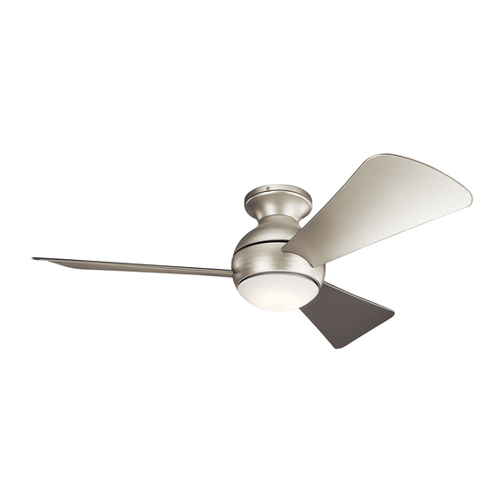
- Page 1 Sola 330150, 330151, 330152 A Kichler Select ceiling fan ® ™ Includes wall mount control system Kichler Lighting ® 7711 East Pleasant Valley Road P.O. Box 318010 Instruction Manual Cleveland, Ohio 44131-8010 Customer Service 866.558.5706 8:30 AM to 5:00 PM EST, Monday - Friday 3066708...
-
Page 2: Safety Rules
1. SAFETY RULES 9. To avoid personal injury or damage to the fan and other items, be cautious when 1. To reduce the risk of electric shock, insure working around or cleaning the fan. electricity has been turned off at the circuit breaker or fuse box before beginning. -
Page 3: Tools And Materials Required
Sola 2. TOOLS AND MATERIALS REQUIRED Philips screw driver Blade screw driver 11 mm wrench Step ladder Wire cutters 3. PACKAGE CONTENTS Unpack your fan and check the contents . You should have the following items: Ceiling Mounting Plate/Bracket Motor Assembly Blade (3) Blade Trim (3) Switch Housing... -
Page 4: Mounting Options
4. MOUNTING OPTIONS If there isn't an existing ETL listed mounting box, then read the following instructions. Disconnect the power by removing fuses or turning off circuit breakers. Secure the outlet box directly to the building structure. Use appropriate fasteners and Outlet box building materials. -
Page 5: Hanging The Fan
Sola 5. HANGING THE FAN REMEMBER to turn off the power before you begin installation. This is necessary for your safety and also the proper programming of the control system. To properly install your ceiling fan, follow the steps below. ETL Listed Outlet Box Step 1. -
Page 6: Make The Electric Connections
6. INSTALLATION THE SAFETY SUPPORT A safety support cable is provided to help prevent Flat Washer the ceiling fan from failing, please install it as Wood Screw follows. Support Brace Spring Washer Step 1. Drive a wood screw and washers into the Ceiling Outlet Box side of the brace that holds the outlet box. -
Page 7: Finishing The Installation
Sola Step 1. Motor to Receiver Electrical Connections: Connect the BLACK wire from the fan to BLACK wire marked "TO MOTOT L" from the receiver. Connect the WHITE wire from the fan to the WHITE wire marked "TO MOTOR N" from the receiver. - Page 8 Step 2. Insert the blade through the slots on the flywheel and attach to the motor hub using the blade screws and blade tirm. Make sure the screws Flywheel Blade securing the blades to the motor hub are tighten and are properly seated. (Fig. 11) Motor Hub Blade Trim Blade Screw...
- Page 9 Sola Step 5. If installing the light kit, skip to step 7. Assembly the light kit wire cover to the switch housing using the two key slots. Replace the removed screw and secure all three screws. Switch Housing (Fig. 14a) Light Kit Wire Cover Screw Fig.
-
Page 10: Installing The Transmitter
9. INSTALLING THE TRANSMITTER All wiring nust be in accordance with the National Electrical Code and local electrical codes. Electrical Outlet Box installation should be performed by a qualified Switch licensed electrician. Wall Plate Select a location to install your wall mount Control System Transmitter. - Page 11 Sola Step 3. You can leave the frequency switches at the factory setting. Or you have to change the dip switch setting in the remote if you are using more than one fan in the same area and want to control them separately. Remove the battery and change the dip switch setting, assuring that they are different from the other fans.
-
Page 12: Troubleshooting
12. TROUBLESHOOTING Problem Solution Fan will not start. 1. Check circuit fuses or breakers. 2. Check all electrical connections to insure proper contact. CAUTION: Make sure the main power is OFF when checking any electrical connection. 3. Make sure the transmitter batteries are installed properly. Positive (+) side facing out. -
Page 13: Specifications
Sola 13. FCC WARNNING: This device complies with part 15 of the FCC Rules. Operation is subject to the folioeing two conditions: (1) This device may not cause harmful interference, and (2) this device must accept any interference received, including interference that may cause undesired operation. Changes or modifictons not expressly approved by the party responsible for compliance could void the user’s authority to operate the equipment.
Need help?
Do you have a question about the Sola 330151 and is the answer not in the manual?
Questions and answers