Advertisement
Available languages
Available languages
Quick Links
Advertisement

Related Manuals for Kichler Lighting 339501AP


Summary of Contents for Kichler Lighting 339501AP
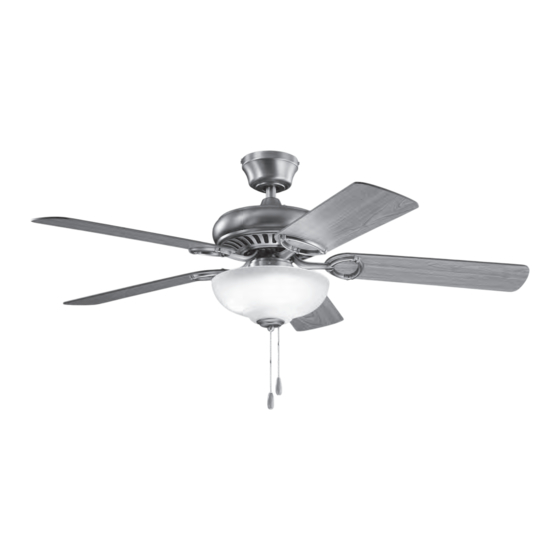
- Page 1 Sutter Place Select ™ Product images may vary slightly from actual product. INSTRUCTION MANUAL...
- Page 2 KICHLER.COM...
- Page 3 TABLE OF CONTENTS SAFETY RULES ..............4 ATTACHING THE FAN BLADES ......... 12 TOOLS AND MATERIALS REQUIRED ....... 5 INSTALLING THE MOUNTING PLATE ....12 PACKAGE CONTENTS ............ 5 INSTALLING THE LIGHT FIXTURE ......13 MOUNTING OPTIONS .............6 INSTALLING THE LAMPS & GLASS SHADE ..14 HANGING THE FAN ............
- Page 4 SAFETY RULES To reduce the risk of electric shock, ensure electricity has been To avoid personal injury or damage to the fan and other items, be turned off at the circuit breaker or fuse box before beginning. cautious when working around or cleaning the fan. Do not use water or detergents when cleaning the fan or fan All wiring must be in accordance with the National Electrical blades.
- Page 5 TOOLS AND MATERIALS REQUIRED • • Phillips screwdriver • Blade screwdriver • 11 mm wrench • Step ladder Wire cutters PACKAGE CONTENTS Unpack your fan and check the contents . You should have the following items: A. Fan blades (5) L.
- Page 6 MOUNTING OPTIONS If there isn’t an existing UL (cUL for Canadian Installation) listed mounting box, then read the following instructions. Disconnect the power by removing fuses or turning off circuit breakers. Outlet Box Secure the outlet box directly to the building structure. Use Fig.
- Page 7 HANGING THE FAN Screws NOTE: This ceiling fan is supplied with two types of hanging assemblies; a downrod Screws Ceiling Mounting Bracket and canopy mounting system and a “close to ceiling” Canopy ONLY system. The “close-to- ceiling” installation is recommended in rooms with less than 8-foot Canopy ceilings or in areas where additional space is desired from the floor to the fan blades.
- Page 8 STANDARD CEILING INSTALLATION Step 3. Carefully feed the electrical lead wires from the fan up through the downrod. Registration Slot Thread the downrod into the coupling until the Hitch pin holes are aligned. Check Tab Next, replace the hitch pin and retaining clip. Tighten both set screws. (Fig. 7) Fig.
- Page 9 INSTALLATION OF SAFETY SUPPORT (required for Canadian installation ONLY) A safety support cable is provided to help prevent the ceiling fan from falling, please install it as follows. Step 1. Attach the provided wood screw and washers to the ceiling joist next to the mounting bracket but do not tighten.
- Page 10 ELECTRICAL CONNECTIONS WARNING: To avoid possible electrical shock, be sure you have turned off the power at Power Lines 120v the main circuit panel. Green Ground Follow the steps below to connect the fan to your household wiring. Use the wire connecting nuts suppled with your fan.
- Page 11 FINISHING THE INSTALLATION Outlet Box STANDARD CEILING INSTALLATION Screws Ceiling Mounting Bracket Screws Step 1. Tuck all the connections neatly into the ceiling outlet box. Step 2. Slide the canopy up to ceiling and attach the canopy to the ceiling mounting Canopy bracket using 4 screws at the top edge of the mounting bracket.
- Page 12 ATTACHING THE FAN BLADES CAUTION: Remove the five rubber shipping blocks attached to the face of the motor. These blocks keep the motor from shifting during shipping and MUST be removed during installation. Screws Step 1. Attach a blade to a blade bracket using the screws and fiber washers provided. Fiber Washers (Fig.
- Page 13 INSTALLING THE LIGHT FIXTURE Wire Connectors Lock Washer Switch Housing 1. Remove the plastic plug from the center of the switch housing. Attach the light Plug fixture to the switch housing by feeding the light fixture wires (black & white) through the hole in the center of the switch housing, then screw the light fixture stem into the center hole.
- Page 14 INSTALLING THE LAMPS AND GLASS SHADE 1. Install 3, 4 Watt, E-12 LED lamps (included). 2. Remove the decorative nut, glass cap and metal nut from the light fixture stem. Slip the beaded pull chain into the outside hole in the glass shade then feed the beaded pull chain from the light fixture stem through the eyelet in the shade.
- Page 15 OPERATING INSTRUCTIONS Turn the power on and check the operation of your ceiling fan. The “center” pull chain turns the light fixture On and Off. The “outside” pull chain controls the 3 speeds of your ceiling fan. 1 pull = High, 2 pulls = Medium, 3 pulls = Low and the 4th pull turns the motor off.
- Page 16 TROUBLESHOOING Problem Solution Fan will not start. 1. Check that all fuses or circuit breakers are installed or in the ON position. 2. Check all electrical connections to ensure proper contact. CAUTION: Make sure the main power is OFF when checking any electrical connection.
- Page 17 SPECIFICATIONS Fan Size Speed Volts Amps Watts CFM/W N.W. G.W. C.F. High 0.42 51.0 4199.05 82.33 52" 8.45 9.45 Medium 0.33 27.8 3252.72 117.00 2.33' 0.19 1792.55 199.17 These are approximate measurements. They do not include data for any lamps or fixtures attached to the ceiling fan. FCC INFORMATION: This device complies with part 15 of the FCC Rules.
- Page 18 KICHLER® LIGHTING 7711 EAST PLEASANT VALLEY ROAD P.O. BOX 318010 CLEVELAND, OHIO 44131-8010 CUSTOMER SERVICE 866.558.5706 8:30 AM TO 5:00 PM EST, MONDAY - FRIDAY...
- Page 19 Sutter Place Select ™ Le produit peut différer légèrement des illustrations. MANUEL D’INSTRUCTIONS...
- Page 20 KICHLER.COM...
- Page 21 TABLE DES MATIÈRES LES RÈGLES DE SÉCURITÉ .......... 4 INSTALLATION DE LA PLAQUE DE MONTAGE.. 12 OUTILS ET MATÉRIAUX REQUIS ........ 5 INSTALLATION DE LUMINAIRE ........ 13 CONTENU DU COLIS ............5 INSTALLATION DES LAMPES ET DE L’OMBRE DE VERRE ................14 OPTIONS DE MONTAGE ..........6 MODE D’EMPLO ..............
- Page 22 LES RÈGLES DE SÉCURITÉ Avant de commencer, assurez-vous que l’électricité a été coupée Pour éviter des blessures ou des dommages au ventilateur et à d’autres au niveau du disjoncteur ou de la boîte à fusibles afin de réduire les objets, soyez prudent lorsque vous travaillez ou nettoyez le ventilateur. risques d’électrocution.
- Page 23 OUTILS ET MATÉRIAUX REQUIS • • Tournevis Philips • Tournevis à lame • Clé de 11 mm • Escabeau Pinces coupantes CONTENU DU COLIS Déballez votre ventilateur et vérifiez le contenu. Vous devriez avoir les éléments suivants: A. Pales de ventilateur (5) L.
- Page 24 OPTIONS DE MONTAGE S’il n’y a pas de boîtier de montage répertorié UL (cUL pour les installations au Canada), lisez les instructions suivantes. Déconnectez l’alimentation en retirant les fusibles ou en désactivant les disjoncteurs. Boîte de sortie Fixez la boîte de sortie directement à la structure du bâtiment. Fig.
- Page 25 SUSPENDRE LE FAN Des vis REMARQUE: Ce ventilateur de plafond est fourni avec deux types d’assemblages Des vis Support de montage suspendus; un système de montage de tige et de verrière et un système SEULEMENT au plafond “au plafond près du plafond”. L’installation “au plafond” est recommandée dans les pièces Canopée avec des plafonds de moins de 8 pieds ou dans les zones où...
- Page 26 INSTALLATION STANDARD AU PLAFOND Étape 3. Faites passer avec précaution les câbles électriques du ventilateur à travers la tige descendante. Vissez la tige dans l’accouplement jusqu’à ce que les trous des goupilles Fente d’inscription d’attelage soient alignés. Onglet Vérifier Ensuite, replacez la goupille d’attelage et le clip de retenue. Serrer les deux vis de pression. (Fig. 7) Étape 4.
- Page 27 INSTALLATION DU SUPPORT DE SÉCURITÉ (requis pour l’installation canadienne UNIQUEMENT) Un câble de sécurité est fourni pour empêcher le ventilateur de plafond de tomber. Veuillez l’installer comme suit. Étape 1. Fixez la vis à bois et les rondelles fournies à la solive de plafond à côté du support de montage, mais ne les serrez pas.
- Page 28 CONNECTIONS ELECTRIQUES ATTENTION: Pour éviter tout risque d’électrocution, assurez-vous que le panneau Lignes électriques 120v de commande principal est hors tension. Terrain vert Suivez les étapes ci-dessous pour connecter le ventilateur au câblage de votre domicile. Utilisez les écrous de connexion fournis avec votre ventilateur. Fixez les connecteurs avec du ruban isolant.
- Page 29 FINITION DE L’INSTALLATION Boîte de sortie INSTALLATION DE PLAFOND STANTARD Des vis Support de montage au plafond Des vis Étape 1. Rentrez soigneusement toutes les connexions dans la boîte de sortie du plafond. Canopée Étape 2. Faites glisser la capote jusqu’au plafond et fixez-la au support de fixation au plafond à...
- Page 30 FIXATION DES PALES DE VENTILATEUR MISE EN GARDE: Retirez les cinq blocs d’expédition en caoutchouc fixés à la face du moteur. Ces blocs empêchent le moteur de se déplacer pendant l’expédition et DOIVENT être retirés lors de l’installation. Des vis Étape 1.
- Page 31 INSTALLATION DE LUMINAIRE Écrou Connecteurs de fil Rondelle de blocage Boîtier de 1. Retirez le bouchon en plastique situé au centre du boîtier de l’interrupteur. Fixez Prise de courant commutation le luminaire au boîtier de l’interrupteur en passant les fils (noir et blanc) du luminaire à...
- Page 32 INSTALLATION DES LAMPES ET DE L’OMBRE DE VERRE 1. Installez 3 lampes DEL E-12 de 4 Watt (incluses). 2. Retirez l’écrou décoratif, le capuchon en verre et l’écrou métallique de la tige du luminaire. Glissez la chaîne à tirer perlée dans le trou extérieur de la nuance en verre, puis passez la chaîne à...
- Page 33 MODE D’EMPLO Allumez l’appareil et vérifiez le fonctionnement de votre ventilateur de plafond. La chaîne de tirage “centre” allume et éteint le luminaire. La chaîne de tirage “extérieur” contrôle les 3 vitesses de votre ventilateur de plafond. 1 traction = haute, 2 tractions = moyenne, 3 tractions = basse et la quatrième traction éteint le moteur.
- Page 34 DÉPANNAGE Problème Solution Le ventilateur ne 1. Vérifiez que tous les fusibles ou les disjoncteurs sont installés ou en position ON. démarre pas. 2. Vérifiez toutes les connexions électriques pour assurer un contact correct. MISE EN GARDE: Assurez-vous que l’alimentation principale est éteinte lors de la vérification de toute connexion électrique. Le ventilateur semble 1.
- Page 35 ESPECIFICACIONES Taille du La vitesse Volts Amplis Watts CFM/W ventilateur High 0.42 51.0 4199.05 82.33 52" 8.45 9.45 Medium 0.33 27.8 3252.72 117.00 2.33' 0.19 1792.55 199.17 Ce sont des mesures approximatives. Ils ne comprennent pas les données pour les lampes ou les luminaires fixés au ventilateur de plafond. FCC INFORMATION: Cet appareil est conforme à...
- Page 36 KICHLER® LIGHTING 7711 EAST PLEASANT VALLEY ROAD P.O. BOX 318010 CLEVELAND, OHIO 44131-8010 SERVICE À LA CLIENTÈLE 866.558.5706 De 08h30 à 17h (heure normale du l’Est), du lundi au vendredi...
- Page 37 Sutter Place Select ™ Las imágenes son de carácter ilustrativo y pueden diferir del producto real. MANUAL DE INSTRUCCIONES...
- Page 38 KICHLER.COM...
- Page 39 ÍNDICE REGLAS DE SEGURIDAD ............4 COLOCACIÓN DE LAS HOJAS DEL VENTILADOR ..12 HERRAMIENTAS Y MATERIALES NECESARIOS ...5 INSTALACIÓN DE LA PLACA DE MONTAJE ....12 CONTENIDOS DEL PAQUETE ..........5 INSTALANDO EL ACCESORIO DE LUZ ......13 OPCIONES DE MONTAJE ............6 INSTALANDO LAS LAMPARAS Y LA SOMBRA DE VIDRIO ..................14 COLGANDO EL VENTILADOR..........
- Page 40 REGLAS DE SEGURIDAD Para reducir el riesgo de descarga eléctrica, asegúrese de que se Para evitar lesiones personales o daños al ventilador y otros haya apagado la electricidad en el disyuntor o en la caja de fusibles elementos, tenga cuidado al trabajar o limpiar el ventilador. antes de comenzar.
- Page 41 HERRAMIENTAS Y MATERIALES REQUERIDOS • • Destornillador Philips • Destornillador de cuchilla • Llave de 11 mm • Escalera de mano Cortadores de alambre CONTENIDOS DEL PAQUETE Desembale su ventilador y verifique el contenido. Debe tener los siguientes elementos: A. Aspas del ventilador (5) L.
- Page 42 OPCIONES DE MONTAJE Si no hay una caja de montaje listada UL (cUL para instalación canadiense), lea las siguientes instrucciones. Desconecte la energía quitando los fusibles o apagando los disyuntores. Caja de salida Asegure la caja de salida directamente a la estructura del edificio. Fig.
- Page 43 COLGANDO EL VENTILADOR Empulgueras NOTA: Este ventilador de techo se suministra con dos tipos de conjuntos colgantes; Empulgueras Soporte de montaje un sistema de montaje de techo y techo y un sistema SOLO de dosel “cerca del techo”. en el techo Se recomienda la instalación “cerca del techo”...
- Page 44 INSTALACIÓN ESTÁNDAR DE TECHO Paso 3. Alimente cuidadosamente los cables conductores eléctricos desde el ventilador a través de la varilla. Enrosque la varilla en el acoplamiento hasta que los orificios del pasador de Espacio de registro enganche estén alineados. Pestaña de Luego, reemplace el pasador de enganche y el clip de retención.
- Page 45 INSTALACIÓN DE SOPORTE DE SEGURIDAD (SOLO para instalación canadiense) Se proporciona un cable de soporte de seguridad para ayudar a evitar que el ventilador de techo se caiga, instálelo de la siguiente manera. Paso 1. Fije el tornillo de madera y las arandelas provistos a la viga del techo junto al soporte de montaje, pero no apriete.
- Page 46 CONEXIONES ELÉCTRICAS ADVERTENCIA: Para evitar una posible descarga eléctrica, asegúrese de haber Líneas eléctricas 120v apagado la alimentación en el panel del circuito principal. Tierra verde Siga los pasos a continuación para conectar el ventilador al cableado de su hogar. Use las tuercas de conexión de cable que se incluyen con su ventilador.
- Page 47 ACABADO DE LA INSTALACIÓN Outlet Box INSTALACIÓN DE TECHO ESTÁNDAR Empulgueras Soporte de montaje en el techo Paso 1. Meta todas las conexiones perfectamente en la caja de salida del techo. Empulgueras Paso 2. Deslice el dosel hasta el techo y fije el dosel al soporte de montaje del techo con 4 tornillos en el borde superior del soporte de montaje.
- Page 48 COLOCACIÓN DE LAS HOJAS DEL VENTILADOR PRECAUCIÓN: Retire los cinco bloques de envío de goma unidos a la cara del motor. Estos bloques evitan que el motor se mueva durante el envío y DEBEN retirarse durante la instalación. Empulgueras Paso 1. Fije una cuchilla a un soporte de cuchilla con los tornillos y arandelas de fibra Arandelas de fibra provistos.
- Page 49 INSTALANDO EL ACCESORIO DE LUZ Nuez Conectores de cable Arandela de seguridad Interruptor de 1. Retire el tapón de plástico del centro de la carcasa del interruptor. Conecte la Enchufe vivienda lámpara a la carcasa del interruptor alimentando los cables de la lámpara (blanco y negro) a través del orificio en el centro de la carcasa del interruptor, luego atornille el vástago de la lámpara en el orificio central.
- Page 50 INSTALANDO LAS LAMPARAS Y LA SOMBRA DE VIDRIO 1. Instale 3, 4 vatios, lámparas LED E-12 (incluidas). 2. Retire la tuerca decorativa, la tapa de vidrio y la tuerca metálica del vástago de la lámpara. Deslice la cadena de tracción con cuentas en el orificio exterior en la pantalla de vidrio y luego alimente la cadena de tracción con cuentas desde el vástago del accesorio de luz a través del ojal en la pantalla.
- Page 51 INSTRUCCIONES DE OPERACIÓN Encienda la alimentación y verifique el funcionamiento de su ventilador de techo. La cadena de tracción “central” enciende y apaga la lámpara. La cadena de tracción “exterior” controla las 3 velocidades de su ventilador de techo. 1 tirón = alto, 2 tirones = medio, 3 tirones = bajo y el cuarto tirón apaga el motor.
- Page 52 SOLUCIÓN DE PROBLEMAS Problema Solución El ventilador no 1. Verifique que todos los fusibles o disyuntores estén instalados o en la posición ON. arranca. 2. Verifique todas las conexiones eléctricas para asegurar un contacto adecuado. PRECAUCIÓN: Asegúrese de que la alimentación principal esté APAGADA cuando verifique cualquier conexión eléctrica. El ventilador suena 1.
- Page 53 ESPECIFICACIONES Tamaño Velocidad Voltios Amplifi- Vatios CFM/W cadores ventilador High 0.42 51.0 4199.05 82.33 52" 8.45 9.45 Medium 0.33 27.8 3252.72 117.00 2.33' kilogramos kilogramos 0.19 1792.55 199.17 Estas son medidas aproximadas. No incluyen datos de ninguna lámpara o accesorio conectado al ventilador de techo. INFORMACIÓN DE LA FCC: Este dispositivo cumple con la parte 15 de las Reglas de la FCC.
- Page 54 KICHLER® LIGHTING 7711 EAST PLEASANT VALLEY ROAD P.O. BOX 318010 CLEVELAND, OHIO 44131-8010 ATENCIÓN AL CLIENTE 866.558.5706 8:30 AM A 5:00 PM EST, LUNES A VIERNES...
Need help?
Do you have a question about the 339501AP and is the answer not in the manual?
Questions and answers