Table of Contents
Advertisement
Advertisement
Table of Contents

Related Manuals for Chauvin Arnoux C.A 6550


Summary of Contents for Chauvin Arnoux C.A 6550
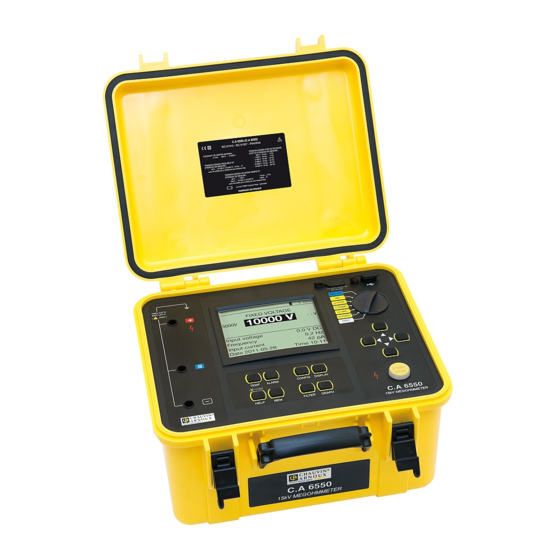
- Page 1 C.A 6550 MEGoHMMEtErS 10 kV ANd 15 kV C.A 6555 User’s manual E N G L I S H...
- Page 2 Thank you for purchasing a megohmmeter C.A 6550 or C.A 6555. For best results from your instrument: „ read these operating instructions carefully, „ comply with the precautions for use. WARNING, risk of DANGER! The operator must refer to these instructions whenever this danger symbol appears.
-
Page 3: Table Of Contents
CoNtENtS 1. CoMMISSIoNING ..................................4 1.1. Unpacking ..................................4 1.2. Specifications label ................................ 5 1.3. Charging the batteries ..............................5 1.4. Adjusting the brightness and contrast ........................... 6 2. dESCrIPtIoN of tHE INStrUMENt ........................... 7 2.1. Functions ..................................8 2.2. Display .................................... 8 2.3. -
Page 4: Commissioning
1. CoMMISSIoNING 1.1. UNPACkING ‘ FICHE DE SÉCURITÉ DU C.A 6116 (FR) Vous venez d’acquérir un contrôleur d’installation C.A 6116 et nous vous remercions de votre confiance. Pour obtenir le meilleur service de votre appareil : lisez attentivement cette notice de fonctionnement, ... -
Page 5: Specifications Label
1.2. SPECIfICAtIoNS LAbEL Attach one of the 5 specifications labels, with your appropriate language, on the inside of the lid. 1.3. CHArGING tHE bAttErIES When using the instrument for the first time, start by fully charging the batteries. Charging must be done at a temperature between 0 and 30°C. -
Page 6: Adjusting The Brightness And Contrast
Battery 1 Full 100% Charging time: 11.4 V 15 mA 55.1°C 02:34:41 Battery 2 Full 100% 11.4 V 15 mA 55.1°C between 6 and 10 hours, depending 02:34:24 on the initial charge condition. Following prolonged storage, the batteries may be completely discharged. In this case, the first charge may last longer. Charging when the instrument is in operation is also possible. -
Page 7: Description Of The Instrument
2. dESCrIPtIoN of tHE INStrUMENt... -
Page 8: Functions
2.1. fUNCtIoNS C.A 6550 and C.A 6555 megohmmeters are high-end portable measuring instruments intended for the measurement of very high electrical insulation and resistance values, mounted in a rugged site housing with a cover; they have graphic screens and can operating on battery or mains power. - Page 9 2.2.2. ExAMPLE of dISPLAy dUrING tHE MEASUrEMENt The measurement smoothing DF 20s ALARM I-LIM filtering is active, with a time 303.3 MΩ Programmed current limitation. constant of 20 seconds. Value of the insulation resistance. 984 V 3.244 µA Current flowing between the Elapsed Time 00:00:48 terminals.
-
Page 10: Keypad
2.3. kEyPAd If the audible signal has not been deactivated in SET-UP, the instrument confirms each key press by an audible beep. If the beep is more acute, pressing the key is prohibited or will have no effect. A long press (press maintained for more than two seconds) is confirmed by a second audible beep. 2.4. -
Page 11: Procedure
3. ProCEdUrE When they leave the factory, the C.A. 6550 and C.A. 6555 are configured so that they can be used without modifying the parameters. For most measurements, you simply choose the test voltage and press the START/STOP button. If you want to modify parameters, most of them can be configured using the CONFIG key, and also in SET-UP. The SET-UP function allows overall configuration of the instrument independently of which measurement functions are chosen. -
Page 12: Ac/Dc Voltage Measurement
3.2. AC/dC VoLtAGE MEASUrEMENt Turning the switch to any insulation measurement position (U-FIXED, U-VAR, U-RAMP, or U-STEP) sets the instrument to AC/ DC voltage measurement. The voltage between the input terminals is measured at all times and indicated as RMS value on the display unit: Input Voltage. - Page 13 3.3.2. wItH A fIxEd VoLtAGE Set the switch to U-FIXED The following screen appears. BURN SET-UP FIXED VOLTAGE 500 V U-STEP -- V 1000 V U-RAMP U-VAR. Input voltage 10 V AC U-FIXED U-FIXED Frequency 50.0 Hz Input current 24.6 pA Date 2011.05.23 Time 10:31 Use the ...
- Page 14 3.3.4. wItH A VoLtAGE rAMP This test is based on the principle that an ideal insulation produces the same resistance whatever the test voltage applied. Any negative variation of the insulation resistance therefore means that the insulation is defective: the resistance of defective insulation decreases as the test voltage increases.
- Page 15 Set the switch to U-STEP. The following screen appears. BURN SET-UP STEP FUNCTION Min. 50 V Max. 500 V U-STEP U-STEP U-RAMP Test Run Time 00:01:40 U-VAR. Input voltage 1 V AC U-FIXED Frequency 50.0 Hz Input current 24.6 nA Date 2011.05.24 Time 15:31 Use the ...
- Page 16 „ High insulation For very high insulation values, connect the small blue high-voltage lead between the earth pick-up of the black lead and the G terminal of the instrument in order to avoid leakage current and capacitive current effects or to eliminate the influence of the surface leakage current.
- Page 17 3.3.7. bEforE tHE MEASUrEMENt It is possible to configure the measurement using the CONFIG key If the U-FIXED or U-VAR. test voltages have been selected, it is possible to select a measurement configuration by pressing the CONFIG key (see §4.3): „...
- Page 18 E-BRK It is possible to view the available digital values by pressing 995 MΩ the DISPLAY key. 528 V Set: 500 V 531 nA Elapsed Time 00:01:12 DAR (30s/60s) 1.00 PI (1.0m/10m) Capacitance DISPLAY In the case of a step test voltage (10 steps at most) or ramp test voltage (3 steps), the progress of the steps is indicated. Step 2/10.
- Page 19 the case of a ramp or step measurement, the measurement result is displayed as follows: Test with programmed duration. E-BRK Value of the insulation resistance. 5.03 GΩ Current at the end of the measurement. 516 V 98.7 nA Value of the test voltage at the Duration of the measurement.
-
Page 20: Error Indications
After a test with programmed duration, pressing the GRAPH key displays the insulation versus time curve (see §4.5). GRAPH Pressing the TEMP key opens the temperature menu (see §4.1). TEMP Pressing the MEM key records the measurements in memory (see §6.1). ... -
Page 21: Dar (Dielectric Absorption Ratio) And Pi (Polarization Index)
3.5. dAr (dIELECtrIC AbSorPtIoN rAtIo) ANd PI (PoLArIzAtIoN INdEx) In addition to the quantitative value of the insulation resistance, it is very useful to calculate the quality ratios of the insulation (the DAR and the PI) because they can eliminate the influence of certain parameters likely to invalidate the “absolute” insulation measurement. - Page 22 „ In automatic configuration (preferable) Press the CONFIG key. CONFIG Total Run Time Manual Stop Manual Stop + DD Timed Run (m:s) 2:00 Timed Run + DD DAR (s/s) 30/60 PI (m/m) 1.0/10 CONFIG Use the keys to select DAR or PI. CONFIG CONFIG Total Run Time...
-
Page 23: Dd (Dielectric Discharge Index)
A capacitance in parallel to the insulation resistance extends the settling times of the measurements. This can affect or even inhibit the measurement of DAR or PI (depending on the time set for recording the first resistance value). The table below indicates the typical values of the capacitances in parallel with the insulation resistance, making it possible to measure the DAR and the PI without changing their preset durations. - Page 24 Use the keys to select Manual Stop + DD or Timed Run + DD (manual or automatic measurement). CONFIG CONFIG Total Run Time Total Run Time 00:03:00 Manual Stop Manual Stop Manual Stop + DD Manual Stop + DD Timed Run (m:s) 2:00 Timed Run (m:s) 2:00...
-
Page 25: Capacitance Measurement
3.6.2. INtErPrEtAtIoN of tHE rESULt Value of dd Quality insulation 7 < DD Very poor 4 < DD < 7 poor 2 < DD < 4 Borderline DD < 2 Good 3.7. CAPACItANCE MEASUrEMENt The capacitance measurement is made automatically during the insulation measurement, and is displayed after the measurement has been stopped and the device tested has been discharged. -
Page 26: Complementary Functions
4. CoMPLEMENtAry fUNCtIoNS 4.1. tEMP kEy This function is accessible only when the measurement is over. It is used to refer the measurement result to a temperature other that the one at which the measurement was made. This is because the temperature causes the resistance to vary according to a quasi exponential law. To a rough approximation, raising the temperature by 10°C halves the insulation resistance;... -
Page 27: Alarm Key
detail concerning the calculation performed: The insulation resistance varies with the measurement temperature. This dependence can be approximated by an exponential function: Rc = K where Rc: insulation resistance referred to 40°C. insulation resistance measured at ambient temperature T. coefficient defined as follows: = (1/2) ^ ((40 - T)/∆T) where ∆T: temperature difference at which the insulation resistance is halved. - Page 28 When you select Timed Run (test with programmed duration) or Timed Run + DD, you can set the duration of the measurement (m:s). CONFIG Total Run Time 00:02:00 Manual Stop Manual Stop + DD Timed Run (m:s) 2:00 To do this, use the and keys. Timed Run + DD DAR (s/s) 30/60...
- Page 29 Stoppage of the test at a preset current (break at I-limit) The measurement will be stopped when the current reaches the maximum value (Maximum Output Current) defined by the user (see below). This type of test is useful for testing varistors or other types of voltage limiter. The I-LIM symbol is displayed.
- Page 30 The RANGE symbol is displayed. RANGE BURN FIXED VOLTAGE 1000 V 500 V 2500 V Input voltage 10 V AC Frequency 50.0 Hz Input current 24.6 nA Date 2011.05.23 Time 10:31 „ Perturbation of the signal (Disturbance Level) Use the keys to set its value, from Low to High. The DH symbol is then displayed. FIXED VOLTAGE 1000 V 500 V...
- Page 31 „ In the U-STEP mode: the programming of the step (Set Step Function). Use the keys to go to Set Step Function; the instrument displays the voltage step values programming screen. This programming can also be done in SET-UP (see §5.4). 4.3.2.
-
Page 32: Display Key
4.4. dISPLAy kEy This key is used to browse through the various accessible screens containing all information available before, during or after the measurement. Depending on the measurement mode and the configuration chosen (CONFIG key), the screens are different. 4.5. GrAPH kEy ... -
Page 33: Filter Key
4.6. fILtEr kEy When the instrument detects that the measurement is disturbed by an AC voltage hat is too large, it switches an analogue filter onto the terminals and so indicates by displaying the DH symbol (Disturbation High). ALARM I-LIM 303.3 MΩ... -
Page 34: Help Key
4.7. HELP kEy A short press on the HELP key opens the help function, in which the actions of the keys are explained. This operation changes with the context: setting of the switch, operating mode, before, during, or after a measurement. -
Page 35: Configuration (Set-Up)
5. CoNfIGUrAtIoN (SEt-UP) This function is used to change the configuration of the instrument by directly accessing the parameters to be modified. Set the switch to SET-UP. The following screen appears. General Settings ET-UP SET-UP Set Default Parameter Buzzer Power Down U-STEP Baud rate 38400... -
Page 36: General Parameters
5.2. GENErAL PArAMEtErS buzzer: to set the audible level of beeps: 1, 2, 3, or Off (no sound). Power down: automatic switching off of the instrument: On (switching off at the end of 5 minutes), Off (no switching off). baud rate: to set the data rate to 9600, 19200, 38400 or 57600 bauds. date: to set the date in yyyy-mm-dd format. -
Page 37: Adjustment Of The Test Voltages
test type: to choose the type of test: Burn-in, Early-Break, or Break at I-Limit. Maximum output Current: to set the maximum output current, from 0.2 to 5mA. Maximum output Voltage: to set the maximum output voltage. This can be useful to prevent handling errors. It make it possible to entrust the instrument to less experienced users, for particular applications (telephony, aviation, etc.) in which it is important not to exceed some maximum test voltage. -
Page 38: Adjustment Of The Alarm Thresholds
You can then set the voltage and duration of each of the 10 steps. The total duration of the measurement (Total Run Time) is calculated by the instrument. The adjustment range of the voltages is from 40 to 15,000V. The duration of the steps ranges from 00:10 to 99:59. If a duration is set to 0, the time displayed is -:- - and the step will be skipped during the test. -
Page 39: Memory Function
6. MEMory fUNCtIoN 6.1. rECordING of tHE MEASUrEMENtS It is possible to record each insulation measurement once it is over. It is not possible to record the voltage measurements. These results are recorded at addresses identified by an object number (OBJ) and a test number (TEST). An object can contain 99 tests. - Page 40 Press the MEM key one last time to record the The instrument confirms the storage. measurement. The measurement is recorded with all its supporting information: the date, the time, the measurement mode, the duration of the measurement, the measurement configuration, the test voltage, the insulation resistance, the capacitance, the residual current, and possibly the DAR, the PI, the DD, the resistance referred to the reference temperature, etc.
-
Page 41: Reading Recorded Values
6.2. rEAdING rECordEd VALUES Set the switch to MR. The instrument indicates the memory occupancy and the object number of the last record made, along with the number of tests it contains. SET-UP 01 08 U-STEP U-RAMP U-VAR. U-FIX Choose the object number using the ... -
Page 42: Erasing The Memory
When the symbol indicates that the samples have been recorded, you can press the GRAPH key to view the curve. Obj. Test Date Time Fct. Recall MEMORY 2011-05-27 10:43 02 02 102 V --- TΩ 00:00:02 Step Function 102 V --- TΩ... - Page 43 6.3.1. ErASING oNE rECord Use the keys to select the record to be erased in Press the CONFIG key. the list of records in memory. The instrument requests confirmation of the deletion. Store MEMORY MEMORY ! WARNING ! Obj. Test Date Time Fct.
-
Page 44: List Of Coded Errors
The instrument in this case completely reformats the memory, which takes a few minutes. During this time, it displays WAIT. The instrument then returns to the memory read entry screen. But since there is no longer any record, it displays: ERROR No data records! 6.4. -
Page 45: Data Transfer Software
7. dAtA trANSfEr SoftwArE The data transfer software supplied with the instrument can be used to export the measurements and to present them in the form of a report. Start by installing the driver and the software Then connect the instrument to the PC using the optical- using the CD supplied with the instrument. -
Page 46: Specifications
8. SPECIfICAtIoNS 8.1. rEfErENCE CoNdItIoNS Influence quantities Reference values Temperature 23 ± 3°C Relative humidity 45 to 55% RH Supply voltage 9 to 12V Frequency range DC and 15.3 … 65Hz Capacitance in parallel on resistance 0µF Electric field null Magnetic field <40A/m the intrinsic uncertainty is the error specified for the reference conditions. - Page 47 „ Maximum current: ≤1mA from 40 to 999V 5 to 0.5mA from 1000 to 15000V. The user can adjust this current. „ Maximum acceptable peak AC voltage: 0,4 Un „ Short-circuit current: ≤5mA ±5%. This current can be limited in SET-UP, to between 0.2 and 5mA. It can also be limited by the maximum output power, which is 10W.
- Page 48 „ Measurement of the dC voltage during the insulation test Input impedance: 3MW up to 1,600V and 300MW thereafter. Specified measurement 40.0 … 99.9 100 … 1500 1600 … 5100 5100 … 16000 range (V) Resolution 0.1V 1-2V 2-4V Intrinsic uncertainty ±1% „...
- Page 49 1000V range 1200 1000 1,E-02 1,E-01 1,E+00 1,E+01 1,E+02 1,E+03 1,E+04 1,E+05 1,E+06 1,E+07 10 k 100 k 10 M 100 M 10 G 100 G 10 T 10 k 100 k 10 M 100 M 10 G 100 G 10 T 2500V range 3000...
- Page 50 5000V range 6000 5000 4000 3000 2000 1000 1,E-02 1,E-01 1,E+00 1,E+01 1,E+02 1,E+03 1,E+04 1,E+05 1,E+06 1,E+07 10 k 10 k 100 k 100 k 10 M 10 M 100 M 100 M 10 G 10 G 100 G 100 G 10 T 10 T...
- Page 51 15000V range 16000 14000 12000 10000 8000 6000 4000 2000 1,E-02 1,E-01 1,E+00 1,E+01 1,E+02 1,E+03 1,E+04 1,E+05 1,E+06 1,E+07 1,E+08 10 k 100 k 10 M 100 M 10 G 100 G 10 T 100 T 10 k 100 k 10 M 100 M 10 G...
-
Page 52: Power Supply
8.3. PowEr SUPPLy Power supply to the instrument is from two rechargeable 9.6V, 4Ah NiMH battery packs. Charging is carried out by connecting the instrument to mains, at a voltage of 90 to 260V and a frequency of 50-60Hz, with an ambient temperature of 0 to 30°C. - Page 53 8.3.4. LIfE bEtwEEN CHArGES The mean battery life depends on the type of measurement and on how the device is used. Test voltage (V) 1000 2500 5000 10000 15000 Number of 5s measurements with 25s pauses 1000 1200 1000 between measurements In U-RAMP or U-STEP mode and when measuring PI, the mean battery life depends essentially on the measurement duration.
-
Page 54: Environmental Conditions
8.4. ENVIroNMENtAL CoNdItIoNS „ range of use The relative humidity can significantly affect insulation. Take care not to make an insulation resistance measurement if the temperature is below the dew point. 0 to 45°C, 0 to 90% RH „ Specified domain of use 0 to 35°C, 0 to 75% RH „... -
Page 55: Intrinsic Uncertainty And Operating Uncertainty
8.8. INtrINSIC UNCErtAINty ANd oPErAtING UNCErtAINty C.A 6550 and C.A 6555 megohmmeters comply with standard IEC-61557, which requires that the operating uncertainty, called B, be less than 30%. √ In insulation measurements, B = ± ( |A| + 1,15 ² + E ²... -
Page 56: Maintenance
9. MAINtENANCE Except for the fuse and the batteries, the instrument contains no parts that can be replaced by personnel who have not been specially trained and accredited. Any unauthorized repair or replacement of a part by an “equivalent” may gravely impair safety. - Page 57 2. Open the cover and turn the instrument over on a table, letting the cover hang open. Unscrew the six captive screws securing the bottom of the housing, without withdrawing it. Housing Table Cover 3. Lift the housing carefully and set it down alongside. The front panel and the electronics remain on the table. Turn this part, holding it by the columns or the front panel.
- Page 58 4. Turn the quarter-turn screw of the battery compartment cover using a tool. The slot of the screw must be perpendicular to the battery compartment cover. Then withdraw the battery compartment cover by sliding it downward. 5. Disconnect the connectors of the two batteries, without pulling on the wires. Withdraw the two batteries from the compartment. Battery compartment cover.
- Page 59 10. Charge the new battery fully before using the instrument. > 90 Vac < 260 Vac 50 / 60 Hz 11. If the battery was disconnected for more than 5 minutes, you may have to reset the date and time of the instrument (see §5). Attention: When the battery is disconnected, even if it is not replaced, it must be fully recharged.
-
Page 60: Metrological Check
This instrument should be checked at least once a year. For checking and calibration, contact one of our accredited metrology laboratories (information and contact details available on request), at our Chauvin Arnoux subsidiary or the branch in your country. 9.3. rEPAIr... -
Page 61: Updating Of The Internal Software
9.4. UPdAtING of tHE INtErNAL SoftwArE With a view to providing, at all times, the best possible service in terms of performance and technical upgrades, Chauvin Arnoux invites you to update the embedded software of the device by downloading the new version, available free of charge on our web site. -
Page 62: Warranty
10. wArrANty Except as otherwise stated, our warranty is valid for twelve months starting from the date on which the equipment was sold. Extract from our General Conditions of Sale provided on request. The warranty does not apply in the following cases: „... -
Page 63: To Order
11. to ordEr Megohmmeter C.A. 6550 ............................P01139705 Megohmmeter C.A. 6555 ............................P01139706 Delivered with bag containing: „ 1 mains power cord, 2m long, „ 1 DataView® data transfer software, „ 1 optical-USB cord, „ 2 safety leads (red and blue), 3 metres long, with high-voltage plugs at both ends, „... - Page 64 Tel: +86 21 65 21 51 96 - Fax: +86 21 65 21 61 07 SCANdINAVIA - CA Mätsystem Ab USA - Chauvin Arnoux Inc - d.b.a AEMC Instruments Box 4501 - SE 18304 TÄBY 200 Foxborough Blvd. - Foxborough - MA 02035...
Need help?
Do you have a question about the C.A 6550 and is the answer not in the manual?
Questions and answers