Table of Contents
Advertisement
Quick Links
Advertisement
Chapters
Table of Contents

Related Manuals for Suzuki Intruder VL1500B


Summary of Contents for Suzuki Intruder VL1500B
- Page 1 VL1500B/T/BT OWNER’S MANUAL...
- Page 2 This manual should be considered a permanent part of the motorcycle and should remain with the motorcycle when resold or otherwise transferred to a new owner or operator. The manual contains important safety information and instructions which should be read carefully before operating the motorcycle.
- Page 3 Proper break-in operation during this time will help ensure maximum life and perfor- mance from your new motorcycle. Suzuki parts are manufactured of high quality mate- rials and machined parts are finished to close tolerances.
- Page 4 WARNING/ CAUTION/NOTICE/NOTE NOTICE Please read this manual and follow its instructions carefully. To emphasize special Indicates a potential hazard that could information, the symbol and the words result in vehicle or equipment damage. WARNING, CAUTION, NOTICE and NOTE have special meanings.
- Page 5 Therefore, your life for your motorcycle. Your authorized model may have different standard features Suzuki dealer has experienced technicians from those shown in this manual. that are trained to provide your machine with the best possible service with the right tools...
-
Page 7: Table Of Contents
TABLE OF CONTENTS CONSUMER INFORMATION CONTROLS FUEL, OIL AND COOLANT RECOMMENDATIONS BREAK-IN (RUNNING-IN) AND INSPECTION BEFORE RIDING RIDING TIPS INSPECTION AND MAINTENANCE TROUBLESHOOTING STORAGE PROCEDURE AND MOTORCYCLE CLEANING SPECIFICATIONS INDEX... -
Page 9: Consumer Information
CONSUMER INFORMATION ACCESSORY USE AND MOTORCYCLE LOADING ................1-2 SAFE RIDING RECOMMENDATION FOR MOTORCYCLE RIDERS ............1-6 LABELS ..............................1-8 SERIAL NUMBER LOCATION ........................1-8 NOISE CONTROL SYSTEM (AUSTRALIA ONLY) .................. 1-10... -
Page 10: Accessory Use And Motorcycle Loading
Install and use them accord- ing the accessories on your motorcycle and ing to their instructions. If you have any consult your Suzuki dealer if you have any questions, contact your Suzuki dealer. questions. -
Page 11: Controls
ACCESSORY INSTALLATION • Certain accessories displace the rider GUIDELINES from his or her normal riding position. • Install aerodynamic-affecting accesso- This limits the freedom of movement of ries, such as a fairing, windshield, back- the rider and may limit his or her control rests, saddlebags, and travel trunks, as ability. - Page 12 LOADING LIMIT • Never exceed the G.V.W. (Gross Vehicle Weight) of this motorcycle. The G.V.W. is WARNING the combined weight of the machine, accessories, payload, rider and passen- ger. When selecting your accessories, Overloading or improper loading can keep in mind the weight of the rider as cause loss of motorcycle control and an well as the weight of the accessories.
- Page 13 LOADING GUIDELINES • Improperly loading your motorcycle can This motorcycle is primarily intended to reduce your ability to balance and steer carry small items when you are not riding the motorcycle. You should ride at with a passenger. Follow the loading guide- reduced speeds, less than 130 km/h (80 lines below: mph), when you are carrying cargo or...
-
Page 14: Safe Riding Recommendation For Motorcycle Riders
SAFE RIDING RECOMMENDATION FOR RIDING APPAREL Loose, fancy clothing can be uncomfortable MOTORCYCLE RIDERS and unsafe when riding your motorcycle. Motorcycle riding is great fun and an excit- Choose good quality motorcycle riding ing sport. Motorcycle riding also requires apparel when riding your motorcycle. that some extra precautions be taken to ensure the safety of the rider and passen- INSPECTION BEFORE RIDING... - Page 15 KNOW YOUR LIMITS RIDE DEFENSIVELY Ride within the boundaries of your own skill The most common type of motorcycle acci- at all times. Knowing these limits and stay- dent occurs when a car traveling towards a ing within them will help you to avoid acci- motorcycle turns round corner in front of the dents.
-
Page 16: Labels
Make sure you understand all of the used to register the motorcycle. They are labels. Do not remove any labels from the also used to assist your authorized Suzuki motorcycle. dealer when ordering parts or referring to special service information. - Page 17 The frame number 1 is stamped on the steering head. The engine serial number 2 is stamped on the crankcase assembly. Please write down the numbers in the box provided below for your future reference. Frame number: Engine number:...
-
Page 18: Noise Control System (Australia Only)
NOISE CONTROL SYSTEM (AUSTRALIA ONLY) TAMPERING WITH NOISE CONTROL SYSTEM PROHIBITED Owners are warned that the law may pro- hibit: (a) The removal or rendering inoperative by any person other than for purposes of maintenance, repair or replacement, of any device or element of design incorpo- rated into any new vehicle for the pur- pose of noise control prior its sale or delivery to the ultimate purchaser or... -
Page 19: Controls
CONTROLS LOCATION OF PARTS ..........................2-2 KEY ................................2-5 IGNITION SWITCH ............................. 2-5 STEERING LOCK ............................2-7 INSTRUMENT PANEL ..........................2-8 LEFT HANDLEBAR ..........................2-19 RIGHT HANDLEBAR ..........................2-22 FUEL TANK CAP ............................2-26 GEARSHIFT LEVER ..........................2-28 REAR BRAKE PEDAL ..........................2-29 HELMET HOLDER ............................ -
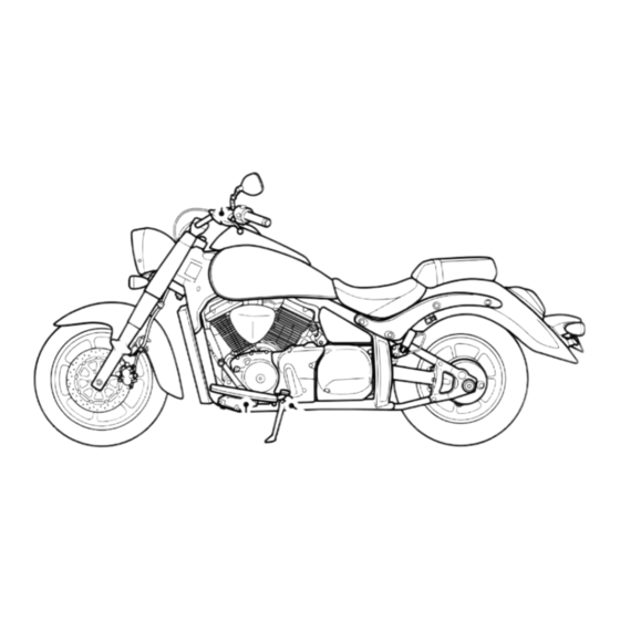
Page 20: Location Of Parts
CONTROLS LOCATION OF PARTS VL1500B VL1500T/BT 1 Clutch lever 5 Right handlebar switches 2 Left handlebar switches 6 Throttle grip 3 Instrument panel 7 Front brake lever 4 Front brake fluid reservoir 8 Fuel tank cap... - Page 21 VL1500B VL1500T/BT 9 Air cleaner G Engine oil filter 0 Spark plug H Footrests A Ignition switch I Engine oil filler cap B Tools J Side stand C Battery and Main fuse K Engine oil drain plug D Helmet holder L Speed sensor E Sidecase (VL1500T/BT) M Engine coolant reservoir...
- Page 22 VL1500B VL1500T/BT O Fuses P Rear brake fluid reservoir Q Steering lock R Rear brake light switch S Rear brake pedal...
-
Page 23: Key
IGNITION SWITCH This motorcycle comes equipped with a The ignition switch has 3 positions: main ignition key and a spare one. Keep the spare key in a safe place. “OFF” POSITION All electrical circuits are cut off. The engine will not start. The key can be removed. - Page 24 If the motorcycle falls down, turn the ignition switch off immediately. Ask your authorized Suzuki dealer to inspect the motorcycle for unseen damage.
-
Page 25: Steering Lock
STEERING LOCK WARNING Moving the motorcycle while the steer- ing is locked can be hazardous. You could lose your balance and fall, or you could drop the motorcycle. Never attempt to move the motorcycle when the steering is locked. Turn the handlebars all the way to the left. -
Page 26: Instrument Panel
SPEEDOMETER 1 INSTRUMENT PANEL The speedometer indicates the road speed in kilometers per hour and miles per hour. If the speedometer needle does not point to zero, follow the procedure below to reset the speedometer. 1. Press and hold the button 9 and turn on the ignition switch. - Page 27 OIL PRESSURE INDICATOR LIGHT “” does not go out, have your authorized Suzuki dealer or a qualified mechanic This indicator light comes on when the inspect your motorcycle. engine oil pressure is below the normal operating range.
- Page 28 COOLANT TEMPERATURE INDICATOR LIGHT “” 5 This indicator light comes on when the cool- ant temperature indicates more than 120°C (248°F). When the coolant temperature indi- cator light comes on, stop the engine and check the coolant level after engine cools. NOTICE GEAR Riding the motorcycle with the coolant...
- Page 29 “FI” at the clock display in the following indicator light comes on, have your two modes; authorized Suzuki dealer or a qualified mechanic inspect the fuel injection sys- A. The display 7 in the odometer display tem as soon as possible.
- Page 30 Suzuki dealer. If the engine stalls, try restarting the engine after turning the ignition switch off and on. •...
- Page 31 COMBINATION SYSTEM DISPLAY 7 The display has six functions, clock, odome- ter, two trip meters, instrument panel light brightness and gear position. When the igni- tion switch is turned to the “ON” position, the display indicates the test pattern shown When the display indicates “CHEC”, check below for two seconds.
- Page 32 GEAR Odometer GEAR GEAR Trip meter A To change the display, push the button 8. The display changes in the order below. GEAR Trip meter B GEAR Instrument panel light brightness 2-14...
- Page 33 Clock WARNING The clock has a 12-hour display. Follow the procedure below to adjust the clock. Changing the display while riding can be hazardous. Removing a hand from the 1. Push the buttons, 8 and 9, simulta- handlebars can reduce your ability to neously for 2 seconds until the hour dis- control the motorcycle.
- Page 34 Odometer The odometer registers the total distance that the motorcycle has been ridden. The odometer ranges from 0 to 999999. NOTE: The odometer display locks at 999999 when the total distance exceeds 999999. GEAR 2-16...
- Page 35 Trip Meters Instrument Panel Light Brightness Pushing the button 9 will change the instru- The two trip meters are resettable odome- ters. They can register two kinds of dis- ment panel light brightness in 6 steps. The tances at the same time. For instance, trip brightness indicator indicates brightness meter A can register the trip distance and from “”...
- Page 36 FUEL METER “” 0 The fuel meter indicates the amount of fuel remaining in the fuel tank. The fuel meter displays all 5 segments when the fuel tank is full. The segment comes on when the fuel level drops below 3.7 L (3.9/3.3 US/Imp qt). The segment blink when the fuel drops below 2.0 L (2.1/1.8 US/Imp qt).
-
Page 37: Left Handlebar
HIGH BEAM INDICATOR LIGHT “” A LEFT HANDLEBAR This blue indicator light will come on when the headlight high beam is turned on. CLUTCH LEVER 1 The clutch lever is used for disengaging the drive to the rear wheel when starting the engine or shifting transmission gears. - Page 38 NOTICE Holding the dimmer switch between the “” and “” position will light both the high and low headlight beam. This improper operation can damage the motorcycle’s headlight. Use the dimmer switch to select only the “” or “” position. DIMMER SWITCH 3 “”...
- Page 39 WARNING NOTICE Do not put objects in front of the head- Failure to use the turn signals, and fail- light or taillight turned on, and do not ure to turn off the turn signals can be cover with clothes when the motorcycle hazardous.
-
Page 40: Right Handlebar
RIGHT HANDLEBAR HAZARD WARNING SWITCH “” 6 All four turn signal lights and indicators will ENGINE STOP SWITCH 1 flash simultaneously when the switch is “” position turned on with the ignition switch in the “ON” The ignition circuit is off. The engine cannot or “P”... - Page 41 FRONT BRAKE LEVER 2 The distance between the throttle grip and The front brake is applied by squeezing the the front brake lever is adjustable to 5 posi- brake lever gently toward the throttle grip. tions. To change the position, push the This motorcycle is equipped with disk brake brake lever forward and turn the adjuster to system and excessive pressure is not...
- Page 42 ELECTRIC STARTER SWITCH “” 3 This switch is used for operating the starter motor. With the ignition switch in the “ON” position, the engine stop switch in “”, the clutch disengaged, push the electric starter switch to operate the starter motor and start the engine.
- Page 43 THROTTLE GRIP 4 NOTICE Engine speed is controlled by the position of the throttle grip. Turn it toward you to Engaging the starter motor for more increase engine speed. Turn it away from than five seconds at a time can damage you to decrease engine speed.
-
Page 44: Fuel Tank Cap
FUEL TANK CAP Use fresh gasoline when filling up the fuel tank. Do not use bad gasoline which is con- taminated with dirt, dust, water or other liq- uid. Be careful that dirt, dust or water does not enter the fuel tank when refueling. NOTE: Place the motorcycle on the side stand to fill up the fuel tank to specified 18.0 L (4.8/4.0 US/Imp gal). - Page 45 WARNING WARNING If you overfill the fuel tank, fuel may Failure to follow safety precautions overflow when it expands due to engine when refueling could result in a fire or heat or heating by the sun. Fuel that cause you to breathe toxic fumes.
-
Page 46: Gearshift Lever
GEARSHIFT LEVER This motorcycle has a 5-speed transmission which operates as shown. To shift properly, squeeze the clutch lever and close the throt- tle at the same time you operate the gear- shift lever. Lift the front end of the gear shift lever or depress the rear end of the gearshift lever to upshift. -
Page 47: Rear Brake Pedal
NOTE: When the transmission is in neutral, REAR BRAKE PEDAL the green indicator light on the instrument panel will be lit. However, even though the light is lit, cautiously and slowly release the clutch lever to make sure that the transmis- sion is positively in neutral. -
Page 48: Helmet Holder
HELMET HOLDER The helmet holder is located on the left side below the rear seat. Insert the key and turn it clockwise to open the latch. Hook your hel- met fastener ring to the latch and turn the key back to lock the holder. ... -
Page 49: Side Stand
SIDE STAND The side stand/ignition interlock system works as follows: • If the side stand is down and the trans- mission is in gear, the engine can not be started. • If the engine is running and the transmis- sion is shifted into gear with the side stand down, the engine will stop running. -
Page 50: Sidecase (Vl1500T/Bt)
SIDECASE (VL1500T/BT) NOTICE If you do not take proper precautions when parking, the motorcycle can fall over. Park the motorcycle on firm, level ground whenever possible. If you must park on an incline, aim the front of the motorcycle uphill and put the transmis- sion into 1st gear to reduce the possibil- ity of rolling off the side stand. - Page 51 To open the sidecase: NOTE: Insert the ignition key into the lock and turn it • Do not keep valuable items in the side- counterclockwise to open the lid. case when leaving the motorcycle unat- tended. NOTE: • Put articles in a waterproof bag when •...
-
Page 53: Fuel, Oil And Coolant Recommendations
FUEL, OIL AND COOLANT RECOMMENDATIONS FUEL OCTANE RATING ..........................3-2 OXYGENATED FUEL RECOMMENDATION ..................... 3-3 ENGINE OIL ..............................3-5 FINAL GEAR OIL ............................3-7 ENGINE COOLANT SOLUTION ........................ 3-8... -
Page 54: Fuel Octane Rating
Use unleaded gasoline with an octane rating not be improved by changing, consult your higher (Research method). Suzuki dealer for its inspection. Unleaded gasoline can extend spark plug life and exhaust components life. (Canada) Your motorcycle requires unleaded gasoline with a minimum pump octane rating of 87 ((R+M)/2 method). -
Page 55: Oxygenated Fuel Recommendation
(Methyl Tertiary Butyl Ether) may be used in such fuels are not the responsibility of your motorcycle if the MTBE content is not Suzuki and may not be covered under the greater than 15%. This oxygenated fuel New Vehicle Limited Warranty or the Emis- does not contain alcohol. - Page 56 NOTE: NOTICE • To help minimize air pollution, Suzuki recommends that you use oxygenated Spilled gasoline containing alcohol can fuels. damage the painted surfaces of your • Be sure that any oxygenated fuel you motorcycle. use has recommended octane ratings.
-
Page 57: Engine Oil
Suzuki recommends the use of SAE 10W- Use Suzuki genuine engine oil or equivalent. 40 engine oil. If SAE 10W-40 engine oil is If Suzuki genuine engine oil is not available, not available, select an alternative according select a proper engine oil according to the to the following chart. - Page 58 JASO T903 Energy Conserving The JASO T903 standard is an index to Suzuki does not recommend the use of select engine oils for 4-stroke motorcycle “ENERGY CONSERVING” or “RESOURCE and ATV engines. Motorcycle and ATV CONSERVING” oils. Some engine oils...
-
Page 59: Final Gear Oil
API SG, SH, SJ or SL FINAL GEAR OIL Use an SAE90 hypoid gear oil which is rated GL-5 under the API classification system. If you operate the motorcycle where ambient 10W-40 temperature is below 0°C (32°F), use an SAE80 hypoid gear oil. Recommended API SH, SJ or SL 10W-40... -
Page 60: Engine Coolant Solution
ENGINE COOLANT SOLUTION WARNING Use “SUZUKI SUPER LONG LIFE COOL- ANT” or “SUZUKI LONG LIFE COOLANT”. Engine coolant is harmful or fatal if swal- If “SUZUKI SUPER LONG LIFE COOLANT” lowed or inhaled. Solution can be poi- and “SUZUKI LONG LIFE COOLANT” are sonous to animals. - Page 61 SUZUKI SUPER LONG LIFE COOLANT NOTICE (Blue) “SUZUKI SUPER LONG LIFE COOLANT” is Spilled engine coolant can damage the pre-mixed to the proper ratio. Add only painted surfaces of your motorcycle. “SUZUKI SUPER LONG LIFE COOLANT” if coolant level drops. It is not necessary to Be careful not to spill any fluid when fill- dilute “SUZUKI SUPER LONG LIFE COOL-...
- Page 62 SUZUKI LONG LIFE COOLANT (Green) Water for mixing Use distilled water only. Water other than distilled water can corrode and clog the alu- minium radiator. Required amount of water/coolant Solution capacity (total): 2700 ml (2.9/2.4 US/Imp. qt) 1350 ml Water (1.4/1.2 US/Imp.
-
Page 63: Break-In (Running-In) And Inspection Before Riding
BREAK-IN (RUNNING-IN) AND INSPECTION BEFORE RIDING MAXIMUM THROTTLE OPENING RECOMMENDATION ................. 4-2 VARY THE ENGINE SPEED ........................4-2 BREAKING IN THE NEW TIRE ........................4-3 AVOID CONSTANT LOW SPEED ......................4-3 ALLOW THE ENGINE OIL TO CIRCULATE BEFORE RIDING ..............4-4 OBSERVE YOUR FIRST AND MOST CRITICAL SERVICE .............. -
Page 64: Maximum Throttle Opening Recommendation
This break-in is to achieve maximum life and per- aids the mating process of the parts. It is formance from your new Suzuki. The follow- essential that some stress be placed on the ing guidelines explain proper break-in engine components during break-in to procedures. -
Page 65: Breaking In The New Tire
BREAKING IN THE NEW TIRE AVOID CONSTANT LOW SPEED New tires need proper break-in to assure Operating the engine at constant low speed maximum performance, just as the engine (light load) can cause parts to glaze and not does. Wear in the tread surface by gradually seat in. -
Page 66: Allow The Engine Oil To Circulate Before Riding
ALLOW THE ENGINE OIL TO CIRCULATE OBSERVE YOUR FIRST AND BEFORE RIDING MOST CRITICAL SERVICE Allow sufficient idling time after warm or cold The initial service (1000 km maintenance) is engine startup before applying load or rev- the most important service your motorcycle ving the engine. -
Page 67: Inspection Before Riding
INSPECTION BEFORE RIDING WARNING WARNING If you operate this motorcycle with improper tires or improper or uneven tire Failure to inspect your motorcycle pressure, you may lose control of the before riding and to properly maintain motorcycle. This will increase your risk your motorcycle increases the chances of an accident. - Page 68 Before riding the motorcycle, be sure to WHAT TO CHECK CHECK FOR: check the following items. Never underesti- mate the importance of these checks. Per- Steering • Smoothness • No restriction of movement form all of them before riding the machine. •...
- Page 69 Tires • Correct pressure ( 6-57) • Adequate tread depth • No cracks or cut Engine oil Correct level ( 6-30) Cooling system • Proper coolant level ( 6-44) • No leaks or damage Gear oil Correct level ( 6-47) Horn Correct function (...
-
Page 71: Riding Tips
RIDING TIPS STARTING THE ENGINE ........................... 5-2 STARTING OFF ............................5-4 USING THE TRANSMISSION ........................5-6 RIDING ON HILLS ............................5-8 STOPPING AND PARKING ........................5-8 CARRYING A PASSENGER ........................5-12... -
Page 72: Starting The Engine
RIDING TIPS NOTE: The fuel supply system stops the engine when the motorcycle is overturned. Turn off the ignition switch before restarting STARTING THE ENGINE the engine. Before attempting to start the engine make sure: When the engine is cold: •... - Page 73 When the engine is hard to start: NOTICE Open the throttle 1/8 to 1/4 turn and push the electric starter switch. Running the engine too long without riding may cause the engine to overheat. WARNING Overheating can result in damage to internal engine components and discol- Exhaust gas contains carbon monoxide, oration of exhaust pipes.
-
Page 74: Starting Off
STARTING OFF WARNING WARNING If you remove even one hand or foot from the motorcycle, you can reduce Riding at excessive speeds increases your ability to control the motorcycle. your chances of losing control of the This could cause you to lose your bal- motorcycle, which can result in an acci- ance and fall off the motorcycle. - Page 75 After moving the side stand to the fully up WARNING position, squeeze the clutch lever in and pause momentarily. Engage first gear by Sudden side winds, which can occur depressing the gearshift lever downward. when being passed by larger vehicles, at Turn the throttle grip a little toward you and tunnel exits or in hilly areas, can cause at the same time release the clutch lever...
-
Page 76: Using The Transmission
USING THE TRANSMISSION Shifting up schedule The transmission is provided to keep the Gear position km/h miles/h engine operating smoothly in its normal operating speed range. The gear ratios have 1st → 2nd been carefully chosen to meet the charac- 2nd →... - Page 77 WARNING WARNING Downshifting when engine speed is too Downshifting while the motorcycle is high can; leaned over in a corner may cause rear • cause the rear wheel to skid and lose wheel skid and loss of control. traction due to increased engine brak- ing, resulting in an accident;...
-
Page 78: Riding On Hills
RIDING ON HILLS STOPPING AND PARKING • When climbing steep hills, the motorcy- 1. Turn the throttle grip away from you to cle may begin to slow down and show close the throttle completely. lack of power. At this point you should 2. - Page 79 WARNING WARNING Inexperienced riders tend to underuti- Hard braking on wet, loose, rough, or lize the front brake. This can cause other slippery surfaces can cause wheel excessive stopping distance and lead to skid and loss of control. a collision.
- Page 80 5. Park the motorcycle on a firm, flat sur- NOTICE face where it will not fall over. Holding the motorcycle stopped with CAUTION throttle and clutch lever operation on inclines damage motorcycle’s A hot muffler can cause severe burns. clutch.
- Page 81 NOTE: If the motorcycle is to be parked on 6. Turn the ignition switch to the “OFF” the side stand on a slight slope, the front position. end of the motorcycle should face “up” the 7. Turn the handlebars all the way to the incline to avoid rolling forward off the side left and lock the steering for security.
-
Page 82: Carrying A Passenger
CARRYING A PASSENGER To help prevent burn injuries, warn your pas- senger not to contact the muffler when Before you invite someone to be a passen- mounting or dismounting your motorcycle. ger on your motorcycle, you need to be thor- oughly familiar with motorcycle operation. -
Page 83: Inspection And Maintenance
INSPECTION AND MAINTENANCE MAINTENANCE SCHEDULE ........................6-2 TOOLS ................................ 6-9 LUBRICATION POINTS ........................... 6-10 BATTERY ..............................6-11 AIR CLEANER ............................6-17 SPARK PLUGS ............................6-25 ENGINE OIL .............................. 6-30 THROTTLE CABLE ADJUSTMENT ......................6-38 ENGINE IDLE SPEED INSPECTION ....................... 6-40 FUEL HOSE .............................. -
Page 84: Maintenance Schedule
Keep your motorcycle in good condition. months. At the end of each interval, be sure Ask your Suzuki dealer or a qualified to inspect, check, lubricate and service as mechanic to perform the maintenance instructed. - Page 85 If you Servicing electric parts with the ignition have any questions regarding maintenance switch in the “ON” position can damage intervals, consult your Suzuki dealer or a the electric parts when the electric cir- qualified mechanic. cuit is shorted.
- Page 86 “SUZUKI SUPER LONG LIFE Replace every 4 years or 48000 km (29000 miles) COOLANT” (Blue) * Engine coolant “SUZUKI LONG LIFE COOL- ( 6-44) ANT” (Green) or an engine cool- – – – ant other than “SUZUKI SUPER LONG LIFE COOLANT” (Blue)
- Page 87 Interval months 1000 6000 12000 18000 24000 Item miles 4000 7500 11000 14500 * Radiator hose ( 6-46) – Final gear oil ( 6-47) – – Clutch cable play ( 6-42) – * Brakes ( 6-49) – Brake hose ( 6-49) * Replace every 4 years –...
- Page 88 * Throttle valve synchronization – “SUZUKI SUPER LONG LIFE – – – – COOLANT” (Blue) * Engine coolant “SUZUKI LONG LIFE COOL- ( 6-44) ANT” (Green) or an engine cool- – – – ant other than “SUZUKI SUPER LONG LIFE COOLANT” (Blue)
- Page 89 Interval months 1000 12000 24000 36000 48000 Item miles 7500 15000 22500 30000 * Radiator hose ( 6-46) – Final gear oil ( 6-47) – – Clutch cable play ( 6-42) – * Brakes ( 6-49) – Brake hose ( 6-49) * Replace every 4 years Inspect every year or 6000 km (4000 miles) Brake fluid (...
-
Page 91: Tools
TOOLS A tool kit is provided with your motorcycle. The tool box is located on the left side of the motorcycle. 1. Unhook the hooks and remove the cover. 2. To open the tool box, insert the ignition key into the lock and turn it counterclock- wise. -
Page 92: Lubrication Points
LUBRICATION POINTS Proper lubrication is important for smooth and long life of each working part of your motorcycle and also for safe riding. It is a good practice to lubricate the machine after a long rough ride and after it gets wet in the rain or after washing it. -
Page 93: Battery
4 Brake lever pivot fluid level and specific gravity. But have your 5 Throttle cable authorized Suzuki dealer check the charging 6 Brake pedal pivot condition of the battery periodically. The standard charging rate is 1.8A × 5 to 10 hours and the maximum rate is 9.0A ×... - Page 94 WARNING NOTICE Diluted sulfuric acid from the battery can Exceeding the maximum charging rate cause blindness or severe burns. for the battery can shorten its life. When working near the battery, use Never exceed the maximum charging proper eye protection and gloves. Flush rate for the battery.
- Page 95 BATTERY REMOVAL To remove the battery, follow the procedure below: 1. Place the motorcycle on the side stand. 3. Push down the front end of the rear seat 2 and pull the seat backward. 2. Remove the bolt 1. 6-13...
- Page 96 4. Remove the bolts and seat band 3. To 5. Disconnect the negative (–) terminal 5. remove the front seat 4, raise the rear 6. Remove the cap. Disconnect the positive end of the front seat and slide it back- (+) terminal 6.
- Page 97 To install the battery: WARNING 1. Install the battery in the reverse order of removal. Batteries contain toxic substances 2. Connect the battery terminals securely. including sulfuric acid and lead. They could cause injury to humans or could NOTICE damage the environment.
- Page 98 For more detailed information about disposing or recycling of the used bat- tery, consult your Suzuki dealer. The crossed-out wheeled bin symbol A located on the battery label indicates that used battery should be collected separately from ordinary household waste.
-
Page 99: Air Cleaner
AIR CLEANER WARNING If the elements have become clogged with dust, intake resistance will increase with a Operating the engine without the air resultant decrease in power output and an cleaner element in place can be hazard- increase in fuel consumption. If you use your ous. - Page 100 NOTICE Failure to inspect the air cleaner element frequently if the vehicle is used in dusty, wet, or muddy conditions can damage your motorcycle. The air cleaner element can become clogged under these condi- tions, and engine damage may result. Always inspect the air cleaner element after riding...
- Page 101 2. Loosen the clamp bolt. 3. Remove the bolts. Unhook the hook. 4. Remove the air cleaner case 1 with the joint tube. LEFT 6-19...
- Page 102 5. Remove the screws. Remove the air cleaner case 2. RIGHT LEFT 6-20...
- Page 103 6. Remove the screws. Remove the air cleaner element 3. RIGHT LEFT 6-21...
- Page 104 NOTICE A torn air cleaner element will allow dirt to enter the engine and can damage the engine. Replace the air cleaner element with a new one if it is torn. Carefully examine the air cleaner element for tears during cleaning.
- Page 105 9. When installing the air cleaner case, align the marks the air cleaner joint tube and the air cleaner chamber. NOTICE Failure to position the air cleaner ele- ment properly can allow dirt to bypass the air cleaner element. This will cause engine damage.
- Page 106 AIR CLEANER DRAIN PLUG RIGHT LEFT 6-24...
-
Page 107: Spark Plugs
Remove the plug and drain water and oil at SPARK PLUGS the periodic maintenance interval. The air cleaner drain plugs are located inside the air SPARK PLUG REMOVAL cleaner box and air cleaner left chamber 1. Place the motorcycle on the side stand. side. - Page 108 FRONT REAR 6-26...
- Page 109 2. Unhook the hooks and pull off the cover. SPARK PLUG INSPECTION 3. Pull off the spark plug caps. 4. Remove the spark plugs with a spark plug wrench. 0.8 – 0.9 mm (0.031 – 0.035 in) Readjust the spark plug gap to 0.8 – 0.9 mm (0.031 –...
- Page 110 This spark plug should be replaced with a ered under warranty. colder plug. Use one of the spark plugs listed or their equivalent. Consult your Suzuki dealer if you are not sure which spark plug is cor- rect for your type of usage. 6-28...
- Page 111 INSTALLATION DENSO REMARKS CPR6EA-9 U20EPR9 Standard NOTICE If the standard plug is CPR7EA-9 U22EPR9 apt to overheat, replace Improper installation of the spark plug with this plug. can damage your motorcycle. An overly- tight or cross-threaded spark plug will NOTE: This motorcycle uses a resistor-type damage the aluminum threads of the cyl- spark plug to avoid jamming electronic inder head.
-
Page 112: Engine Oil
ENGINE OIL NOTICE Long engine life depends much on the selection of a quality oil and the periodic Dirt can damage the moving engine changing of the oil. Daily oil level checks and parts of your motorcycle if it enters an periodic changes are two of the most impor- open spark plug hole. - Page 113 Check the engine oil level with the engine oil The engine oil level inspection should be dipstick. The dipstick comes out together performed under the following conditions: with the oil filler cap as shown. The level on the dipstick should be between the “L” (Low) 1.
- Page 114 ENGINE OIL AND FILTER CHANGE NOTICE Change the engine oil and oil filter at the scheduled time. The oil should be changed Operating the motorcycle with too little when the engine is warm so that the oil will or too much oil can damage the engine. drain thoroughly from the engine.
- Page 115 CAUTION Hot engine oil and exhaust pipes can burn you. Wait until the oil drain plug and exhaust pipes are cool enough to touch with bare hands before draining oil. 3. Place a drain pan under the drain plug. 4.
- Page 116 WARNING Children and pets may be harmed by swallowing new or used oil. Repeated, prolonged contact with used engine oil may cause skin cancer. Brief contact with oil may irritate skin. Keep new and used oil and used oil fil- ters away from children and pets.
- Page 117 5. Turn the oil filter 4 counterclockwise 6. Wipe off the mounting surface 5 on the and remove it with a Suzuki “cap type” oil engine where the new filter will be filter wrench or a “strap type” filter seated with a clean rag.
- Page 118 6 of the new oil filter. NOTICE Failure to use an oil filter with the correct design and thread specifications can damage your motorcycle’s engine. Be sure to use a genuine Suzuki oil filter or an equivalent one designed for your motorcycle. 6-36...
- Page 119 9. Mark the top dead center position on the “cap type” filter wrench or on the oil filter. Mark top dead center Use an oil filter wrench to tighten the fil- ter 2 turns or to specified torque. Oil filter wrench Oil filter tightening torque: 20 N·m (2.0 kgf-m, 14.5 lbf-ft) 10.
-
Page 120: Throttle Cable Adjustment
THROTTLE CABLE ADJUSTMENT NOTICE Engine damage may occur if you use oil that does not meet Suzuki’s specifica- tions. Be sure to use the oil specified in the FUEL, OIL AND ENGINE COOLANT REC- OMMENDATIONS section. 11. Check the oil level according to Oil Level Check procedure. - Page 121 To adjust the cable play: THROTTLE CABLE BOOTS 1. Loosen the lock nut 1. 2. Turn the adjuster 2 so that the throttle grip has 2.0 – 4.0 mm (0.08 – 0.16 in) play. 3. Tighten the lock nut 1. ...
-
Page 122: Engine Idle Speed Inspection
Remove the seat by referring to the BAT- NOTE: If the engine idle speed is not within TERY section. the specified range, ask your Suzuki dealer or a qualified mechanic to inspect and repair the motorcycle. 2. Remove the bolts. - Page 123 3. Disconnect the coupler 1 and remove 4. Remove the bolt 3. Raise the rear end the instrument panel assembly 2. of the fuel tank and slide it backward. 6-41...
-
Page 124: Clutch Adjustment
CLUTCH ADJUSTMENT Clutch cable play should be 10 – 15 mm (0.4 – 0.6 in) measured at the clutch lever end. Adjust clutch cable play according to the fol- lowing procedure: Minor Adjustment 5. Inspect the fuel hose for damage and fuel leakage. - Page 125 Major Adjustment 2. Loosen the lock nuts 3 and turn the nuts to obtain the correct clutch lever 1. Remove the 3 bolts. Remove the cover. play. 3. Minor adjustment can be made with the clutch lever side adjuster 1. 4.
-
Page 126: Coolant
3. NOTE: Any maintenance of the clutch other than the clutch cable play adjustment should be performed by your Suzuki dealer. The engine coolant solution should be between the “F” (full) and “L” (low) level lines on the engine coolant reservoir. If the level is lower than “L”... - Page 127 NOTE: • Check the coolant level when the engine is cold. • If the engine coolant reservoir is empty, check the radiator coolant level. To add specified engine coolant: 1. Place the motorcycle on the side stand. 3. Remove the filler cap and add specified engine coolant through the filler hole.
- Page 128 If any medical attention. Wash thoroughly after defects are found, ask your Suzuki dealer to handling. Keep out of the reach of chil- replace the radiator hose with a new one.
-
Page 129: Final Gear Oil
FINAL GEAR OIL 3. Drain the oil by removing the drain plug 2 into a suitable container from the bot- Change the gear oil at initial 1000 km (600 tom of the final gear case while holding miles) and inspect every 12000 km (7500 the motorcycle vertically. - Page 130 WARNING WARNING Operating the motorcycle with too little Children and pets may be harmed by final gear oil can cause the final drive swallowing new or used oil. Repeated, unit to lock up and cause an accident. prolonged contact with used engine oil may cause skin cancer.
-
Page 131: Brakes
Inspect the brake hoses and hose joints for increase your chance of having an acci- cracks, damage or brake fluid leakage. If dent. any defects are found, ask your Suzuki dealer to replace the brake hose with a new Be sure to inspect the brakes before one. - Page 132 BRAKE FLUID FRONT REAR Check the brake fluid level in both the front and rear brake fluid reservoirs. Inspect for brake pad wear and leaks. 6-50...
- Page 133 WARNING WARNING Brake fluid will gradually absorb mois- The use of any fluid except DOT4 brake ture through the brake hoses. Brake fluid fluid from a sealed container can dam- with high water content lowers the boil- age the brake system and lead to an ing point and can cause brake system accident.
- Page 134 WARNING NOTICE Brake fluid is harmful or fatal if swal- Spilled brake fluid can damage painted lowed, and harmful if it comes in contact surfaces and plastic parts. with skin or eyes. Solution can be poi- sonous to animals. Be careful not to spill any fluid when fill- ing the brake fluid reservoir.
- Page 135 1. If a front or rear pad is worn to the grooved wear limit line both front or both rear pads must be replaced with new ones by your autho- rized Suzuki dealer or qualified service mechanic. REAR 6-53...
- Page 136 If you need to replace brake pads, have your Suzuki dealer do this work. Inspect After brake system repair or brake pad and maintain the brake pads as recom- replacement, pump the brake lever/pedal mended.
- Page 137 REAR BRAKE PEDAL ADJUSTMENT WARNING CAUTION Replacing only one of the two brake pads can result in uneven braking action A hot muffler can burn you. The muffler and can increase your chance of having will be hot enough to burn you for some an accident.
- Page 138 1. Loosen the lock nut 1, and turn the 110 – 120 mm push rod 2 to locate the pedal 110 – (4.3 – 4.7 in) 120 mm (4.3 – 4.7 in) above the top face of the footrest. 2. Retighten the lock nut 1 to secure the push rod 2 in the proper position.
-
Page 139: Tires
REAR BRAKE LIGHT SWITCH TIRES WARNING The tires on your motorcycle form the crucial link between your motorcycle and the road. Failure to take the precau- tions below may result in an accident due to tire failure. • Check tire condition and pressure before each ride, and adjust pressure if necessary. - Page 140 TIRE PRESSURE AND LOADING WARNING Proper tire pressure and proper tire loading are important factors. Overloading your tires Failure to perform break-in of the tires can lead to tire failure and loss of motorcycle could cause tire slip and loss of control, control.
- Page 141 Cold tire inflation pressure Under-inflated tires make smooth cornering difficult, and can result in rapid tire wear. Over-inflated tires cause smaller amount of LOAD DUAL RIDING SOLO RIDING OR SOLO tire to be in contact with the road, which can WITH LIGHT OR RIDING WITH contribute to skidding and loss of control.
- Page 142 TIRE CONDITION AND TYPE Proper tire condition and proper tire type affect motorcycle performance. Cuts or cracks in the tires can lead to tire failure and loss of motorcycle control. Worn tires are susceptible to puncture failures and subse- quent loss of motorcycle control. Tire wear also affects the tire profile changing motor- cycle handling characteristics.
- Page 143 TYPE an accident, or can wear out sooner. G853 G G852 G • Ask your Suzuki dealer or a qualified Always balance the wheel after repairing a mechanic to perform tire repair, puncture or replacing the tire. Proper wheel replacement, and balancing because...
- Page 144 WARNING • Do not use an external repair plug to repair a puncture since the plug may work loose as a result of the cornering Failure to follow the instructions below forces experienced by a motorcycle for tubeless tires may result in an acci- tire.
-
Page 145: Side Stand/Ignition Interlock System
Have your motorcycle inspected by an authorized Suzuki dealer or a qualified ser- vice mechanic. Check the side stand/ignition interlock sys- tem for proper operation as follows: 1. -
Page 146: Front Wheel Removal
2. Loosen the axle holder bolt 1 on the starting off. right front fork. Loosen the axle shaft 2 temporarily. NOTE: A special tool is necessary to loosen the axle shaft 2. The special tool is avail- able from a Suzuki dealer. 6-64... - Page 147 3. Place an accessory service stand or equivalent under the swingarm to help stabilize the rear end. Carefully position a jack under the engine or chassis tubes and raise the jack until the front wheel is slightly off the ground. NOTICE Improper jacking may cause damage to the oil filter.
- Page 148 6. To reinstall the wheel assembly, reverse the sequence described above. 7. After installing the wheel, apply the front brake several times to restore the proper lever stroke. WARNING Failure to extend brake pads after install- ing the wheel can cause poor braking performance and may result in an acci- 5.
-
Page 149: Rear Wheel Removal
If you do not have a torque wrench or do not know how to use one, ask your authorized Suzuki NOTICE dealer to check the bolts and nuts. Removing the rear wheel without use of... - Page 150 1. Place the motorcycle on the side stand. 2. (VL1500T/BT) Open the right sidecase by referring to the SIDECASE section. Remove the bolts and right sidecase. 3. (VL1500T/BT) Remove the bolts and sidecase brace 1 and 2. 6-68...
- Page 151 5. Remove the axle nut 3. 4. Remove the cap. CAUTION A hot muffler can burn you. Wait until the muffler cools before removing the axle nut. 6-69...
- Page 152 6. Place an accessory service stand or equivalent under the swingarm or chas- sis tubes to stabilize the rear end. 7. Draw out the axle. 8. Remove brake caliper bracket mounting bolt 4. Remove the brake cali- per assembly 5. 6-70...
- Page 153 11. To replace the wheel reverse the com- plete sequence listed. Rear brake caliper bracket mounting bolt tightening torque: 94 N·m (9.4 kgf-m, 68.0 lbf-ft) NOTE: Apply a drop of SUZUKI THREAD LOCK “1322D” to the rear brake caliper bracket mounting bolt 4. 6-71...
-
Page 154: Light Bulb Replacement
LIGHT BULB REPLACEMENT Headlight 12V 60/55W (H4) The wattage rating of each bulb is shown on Front 12V 21W the chart below. When replacing a burned Turn signal light out bulb, always use the exact same wattage Rear 12V 21W rating. - Page 155 HEADLIGHT To replace the headlight bulb, follow the pro- cedure below: 2. Remove the bolts. Unhook the hooks. Remove the headlight assembly 2. 1. Remove the right and left bolts. Unhook the hooks. Remove the headlight cover 6-73...
- Page 156 3. Disconnect the socket 3 from the head- 4. Unhook the bulb holder spring 5, and light and remove the rubber cap 4. pull out the bulb 6. 6-74...
- Page 157 POSITION LIGHT NOTICE (if equipped) The headlight bulb’s life may be short- ened by oil from your fingers if you touch it. When replacing the headlight bulb, be careful not to touch the glass. Grasp the new bulb with a clean cloth. 5.
- Page 158 HEADLIGHT BEAM ADJUSTMENT The headlight beam can be adjusted both up and down or right and left if necessary. 2. Pull off the bulb from the socket. To adjust the beam up and down: Turn the adjuster 1 clockwise or counter- clockwise.
- Page 159 TURN SIGNAL LIGHTS To replace the turn signal light bulbs, follow the procedure below: To adjust the beam right and left: Turn the adjuster 2 clockwise or counter- clockwise. 1. Remove the screw 1. 2. Turn the lens counterclockwise and remove it.
- Page 160 NOTICE Overtightening the screws when rein- stalling the lens may cause the lens to crack. Tighten the screws only until they are snug. 3. Push in on the bulb 2, turn it to the left and pull it out. 4. To fit the replacement bulb, push it in and turn it to the right while pushing.
- Page 161 LICENSE PLATE LIGHT To replace the license plate light bulb, follow the procedure steps: 2. Pull off the bulb from the socket. 1. Turn the license plate lens counterclock- wise and remove it. 6-79...
-
Page 162: Fuses
If the new fuse blows in a short time, the fuse. Consult your Suzuki dealer for the electrical problem may not be fixed. electrical system check and repair. - Page 163 MAIN FUSE FUSES The main fuse is located under the front The fuses are located under the front seat. seat. One 30A spare fuse is located in the Two spare fuses (10A and one 15A) are pro- fuse box. vided in the fuse box. 6-81...
-
Page 164: Catalytic Converter
FUSE LIST CATALYTIC CONVERTER • 30A MAIN fuse protects all electrical cir- The purpose of the catalytic converter is to cuits. minimize the amount of harmful pollutants in • 10A HEAD-HI fuse protects the speed- your motorcycle’s exhaust. Use of leaded ometer and headlight high beam. - Page 165 • Do not try to start the engine by NOTICE pushing the motorcycle or by coast- ing down a hill. Improper motorcycle operation can • Do not idle the engine with any cause catalyst or other motorcycle dam- spark plug wires disconnected or age.
- Page 166 WARNING If you park or operate the motorcycle in areas where there are combustible mate- rials such as dry grass or leaves, these materials may come in contact with the catalytic converter or other hot exhaust components. This can cause a fire. Avoid parking or operating your vehicle in areas with any combustible materials.
-
Page 167: Troubleshooting
TROUBLESHOOTING FUEL SUPPLY CHECK ..........................7-2 IGNITION SYSTEM CHECK ........................7-3 ENGINE STALLING ............................ 7-4... - Page 168 This troubleshooting guide is provided to system, take your machine to an authorized help you find the cause of some common Suzuki dealer. Refer to the “INSTRUMENT complaints. PANEL” section for an explanation of fuel injection system indicator.
- Page 169 If the ignition system is operating properly, a blue spark should jump across the spark plug gap. If there is still no spark, take your motor- cycle to an authorized Suzuki dealer.
- Page 170 Suzuki dealer. Refer to the “INSTRUMENT PANEL” section for an Do not perform this check if you are not explanation of fuel injection system indi- familiar with the procedure.
-
Page 171: Storage Procedure And Motorcycle Cleaning
STORAGE PROCEDURE AND MOTORCYCLE CLEANING STORAGE PROCEDURE ........................... 8-2 PROCEDURE FOR RETURNING TO SERVICE ..................8-4 CORROSION PREVENTION ........................8-4 MOTORCYCLE CLEANING ........................8-6 INSPECTION AFTER CLEANING ......................8-9... -
Page 172: Storage Procedure
For this reason, Suzuki recommends that you trust this maintenance ENGINE work to your authorized Suzuki dealer. If you 1. Remove the spark plugs. Pour one table- wish to service the machine for storage spoon of motor oil into each spark plug yourself, follow the general guidelines holes. - Page 173 BATTERY MAINTENANCE DURING STORAGE 1. Remove the battery from the motorcycle Once a month, recharge the battery. The by referring to the BATTERY section. standard charging rate is 1.8A × 5 to 10 2. Clean the outside of the battery with a hours.
-
Page 174: Procedure For Returning To Service
PROCEDURE FOR RETURNING TO CORROSION PREVENTION SERVICE It is important to take good care of your motorcycle to protect it from corrosion and 1. Clean the entire motorcycle. keep it looking new for years to come. 2. Reinstall the battery by referring to the BATTERY section. - Page 175 Should you find any chips or scratches in cover for your motorcycle. the paint, touch them up immediately to prevent corrosion from starting. If the chips or scratches have gone through to the bare metal, have a Suzuki dealer make the repair.
-
Page 176: Motorcycle Cleaning
MOTORCYCLE CLEANING NOTE: Avoid spraying or allowing water to flow over the following places: WASHING THE MOTORCYCLE • Ignition switch When washing the motorcycle, follow the • Spark plugs instructions below: • Fuel tank cap 1. Remove dirt and mud from the motorcy- •... - Page 177 3. Once the dirt has been completely NOTICE removed, rinse off the detergent with running water. High pressure washers such as those 4. After rinsing, wipe off the motorcycle found at coin-operated car washes have with a wet chamois or cloth and allow it enough pressure to damage the parts of to dry in the shade.
- Page 178 Replace the windshield if Clean only with soft cloth and warm it becomes scratched or discolored so as to water with mild detergent. obstruct view. When replacing the wind- shield, use a Suzuki replacement wind- shield.
-
Page 179: Inspection After Cleaning
SPECIAL CARE FOR MATTE FINISH INSPECTION AFTER CLEANING PAINT For extended life of your motorcycle, lubri- Do not use polishing compounds or waxes cate it according to the GENERAL LUBRI- that contain polishing compounds on sur- CATION section. faces which have a matte finish. The use of polishing compounds will... -
Page 180: Specifications
SPECIFICATIONS DIMENSIONS AND CURB MASS Overall length ............... 2570 mm (101.2 in) 2560 mm (100.8 in) ... Canada and Australia Overall width................. 990 mm (39.0 in) Overall height ............... 1135 mm (44.7 in) 1440 mm (56.7 in) ... VL1500T/BT Wheelbase ................1675 mm (65.9 in) Ground clearance.............. - Page 181 DRIVE TRAIN Clutch ................... Wet multi-plate type Transmission ................ 5-speed constant mesh Gearshift pattern ..............1-down, 4-up Primary reduction ratio ............1.407 (76/54) Gear ratios, Low ..............2.187 (35/16) 2nd ..............1.400 (28/20) 3rd ..............1.038 (27/26) 4rd ..............0.875 (28/32) Top..............
- Page 182 ELECTRICAL Ignition type ................Electronic ignition (Transistorized) Spark plug ................NGK CPR6EA-9 or DENSO U20EPR9 Battery.................. 12V 64.8kC (18Ah)/10HR Generator ................Three-phase A.C. Generator Main fuse................30A Fuse ..................10/10/15/10/10/15/10A Headlight ................12V 60/55W (H4) Position light (if equipped) ............ 12V 5W Brake light/Taillight..............
- Page 183 CAPACITIES Fuel tank................18.0 L (4.8/4.0 US/lmp. gal) Engine oil, without filter change .......... 3000 ml (3.2/2.6 US/lmp. qt) With filter change ..........3200 ml (3.4/2.8 US/lmp. qt) Final gear oil................. 200 – 220 ml (6.8/7.0 – 7.4/7.7 US/lmp. oz) Engine coolant..............
-
Page 184: Index
INDEX ACCESSORY USE AND MOTORCYCLE ENGINE COOLANT SOLUTION ....3-8 LOADING............1-2 ENGINE IDLE SPEED INSPECTION..6-40 AIR CLEANER..........6-17 ENGINE OIL ........3-5 6-30 ALLOW THE ENGINE OIL TO CIRCULATE ENGINE STALLING ........7-4 BEFORE RIDING ........4-4 AVOID CONSTANT LOW SPEED .....4-3 FINAL GEAR OIL ...... - Page 185 HELMET HOLDER ........2-30 LABELS ............1-8 LEFT HANDLEBAR........2-19 LIGHT BULB REPLACEMENT....6-72 LOCATION OF PARTS ......2-2 IGNITION SWITCH........2-5 LUBRICATION POINTS ......6-10 IGNITION SYSTEM CHECK ......7-3 INSPECTION AFTER CLEANING....8-9 INSPECTION BEFORE RIDING ....4-5 INSTRUMENT PANEL .......2-8 MAINTENANCE SCHEDULE..... 6-2 MAXIMUM THROTTLE OPENING RECOMMENDATION.........
- Page 186 NOISE CONTROL SYSTEM PROCEDURE FOR RETURNING TO (AUSTRALIA ONLY).........1-10 SERVICE............ 8-4 OBSERVE YOUR FIRST AND REAR BRAKE PEDAL......2-29 MOST CRITICAL SERVICE .......4-4 REAR WHEEL REMOVAL ....... 6-67 OXYGENATED FUEL RIDING ON HILLS........5-8 RECOMMENDATION.........3-3 RIGHT HANDLEBAR ....... 2-22...
- Page 187 SAFE RIDING RECOMMENDATION FOR THROTTLE CABLE ADJUSTMENT..6-38 MOTORCYCLE RIDERS......1-6 TIRES ............6-57 SERIAL NUMBER LOCATION ....1-8 TOOLS ............6-9 SIDE STAND ..........2-31 SIDE STAND/IGNITION INTERLOCK SYSTEM ...........6-63 USING THE TRANSMISSION....5-6 SIDECASE (VL1500T/BT) ......2-32 SPARK PLUGS ........6-25 STARTING OFF .........5-4 VARY THE ENGINE SPEED......
- Page 191 Part No. 99011-06J52-01A December, 2014 EN Printed in Japan © COPYRIGHT SUZUKI MOTOR CORPORATION 2014...
Need help?
Do you have a question about the Intruder VL1500B and is the answer not in the manual?
Questions and answers
Fuse box location
The fuse box on a Suzuki Intruder VL1500B is located under the front seat.
This answer is automatically generated