Table of Contents
Advertisement
Quick Links
Advertisement
Table of Contents

Subscribe to Our Youtube Channel
Related Manuals for UTT N518W

Summary of Contents for UTT N518W
-
Page 1: User Manual
User Manual Enterprise Wireless Router... -
Page 2: Copyright Notice
Trademark ® is a registered trademark of Shanghai UTT Technologies Co., Ltd. Other trademarks and registered trademarks of products mentioned in this publication may be the properties of their respective owners and are only used for identification purposes. -
Page 3: Table Of Contents
Table of Contents About this Manual ........................... 1 Manual Description ......................1 Web UI Style ........................1 Documents Conventions ....................2 0.3.1 Format ........................2 0.3.2 Icons ........................2 Factory Default Settings ....................3 Contact us ........................3 Chapter 1. Hardware Installation ....................4 Panel Description ...................... - Page 4 Load Balancing ......................25 4.2.1 Internet Connection Detection Mechanism ............25 4.2.2 Global Settings ....................26 4.2.3 Load Balancing List ..................... 28 4.2.4 Detection and Bandwidth ..................29 4.2.5 Identity Binding ....................30 LAN ..........................30 DHCP Server ....................... 32 4.4.1 DHCP Server Settings ..................
- Page 5 MAC Filtering ....................... 62 Advanced ........................63 Client List ........................63 Chapter 7. Advanced Menu ......................64 NAT&DMZ ........................64 7.1.1 Port Forwarding ....................64 7.1.2 NAT Rule ......................68 7.1.3 DMZ ........................74 7.1.4 Priorities for Port Forwarding and DMZ Host ............75 Static Route........................
- Page 6 9.4.2 Account Settings ....................111 9.4.3 Client Status ...................... 112 9.4.4 The steps for using Web Authentication ............. 112 User Group ........................ 114 Chapter 10. App Control Menu ....................116 10.1 Schedule ........................ 116 10.2 Application Control ....................117 10.3 QQ Whitelist ......................
- Page 7 13.3.2 Creating Security Associations (SAs) ............... 171 13.3.3 Maintain Security Associations (SAs) ............... 173 13.3.4 IPSec NAT Traversal ..................174 13.3.5 IPSec List ......................175 13.3.6 IPSec settings ....................175 13.3.7 Example of IPSec .................... 181 Chapter 14. System Menu ...................... 188 14.1 Administrator ......................
-
Page 8: About This Manual
V1.7.5. As the product or firmware version upgrades, or other reasons, this guide will be updated periodically. In addition, as the product specifications of each model are different, please contact the UTT customer to ask for help if any questions. -
Page 9: Documents Conventions
UTT Technologies About this Manual list is inactive, it displays a single item. When activated, it drops down a list of items, from which you may select one. Documents Conventions 0.3.1 Format Notes: You need to pay attention to the notes content. -
Page 10: Factory Default Settings
UTT Technologies About this Manual Factory Default Settings The factory default settings of interfaces are shown in the following table. Parameter Default Value Description User Name admin Both the User Name and Password are case sensitive. Password admin You can use this IP address to LAN IP Address 192.168.1.1/255.255.255.0... -
Page 11: Chapter 1. Hardware Installation
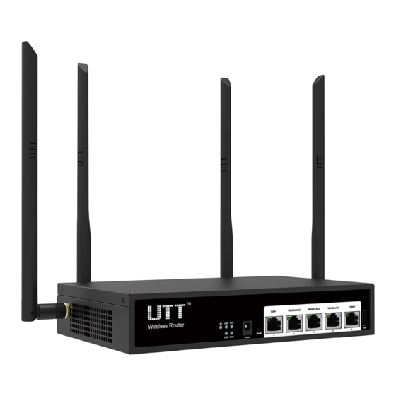
UTT Technologies Hardware Installation Chapter 1. Hardware Installation This chapter describes the physical characteristics of the Device and explains how to install them. Panel Description 1) Front Panel The LED indicators, the interface and the button are located on the front panel of the Device, here we use AC750GW as an example, as for other models, please see the product. -
Page 12: Installation Guideline
UTT Technologies Hardware Installation Interface Description These interfaces provide a LAN connection to network devices, such as PCs LAN Port or switches. The WAN interface is connected to your Internet devices, such as PCs or WAN Port switches. The number of WAN ports depends on the device model. -
Page 13: Installation Requirements
UTT Technologies Hardware Installation Make sure that there is proper heat dissipation and adequate ventilation around the Device. Position the Device out of direct sunlight and away from sources of heat and ignition. Please install the Device in a place far away from the High Power Radio or Radar Station. - Page 14 UTT Technologies Hardware Installation After that, please install the Device according to the following steps (Here we use UTT AC750GW as an example). Don’t forget to pull out the power plug and keep your hands dry. 1) Power off your PC(s), Cable/DSL modem, and the Device.
-
Page 15: Chapter 2. Logging To The Device
UTT Technologies Logging to the Device Chapter 2. Logging to the Device This chapter describes how to configure TCP/IP settings on your computer, and how to login to the Device. In addition, it briefly describes the layout of the Device’s Web interface. -
Page 16: Logging To The Device
UTT Technologies Logging to the Device An unsuccessful ping will look like this: Pinging 192.168.1.1 with 32 bytes of data: Request timed out. Request timed out. Request timed out. Request timed out. Ping statistics for 192.168.1.1: Packets: Sent = 4, Received = 0, Lost = 4 (100% loss), If the Ping command is successful, the connection between the computer and the Device is working properly. - Page 17 Step 3: After login the Device, the first screen that appears is the Homepage. Figure 2-3 Homepage Homepage Description: 1) On the top right corner, there is UTT logo, model and version information, and quick link icons. http://www.uttglobal.com Page 10...
- Page 18 UTT Technologies Logging to the Device (1) UTT Logo: Click to go to the home page on the UTT website. (2) Model, Hardware Version and Software Version: Displays the model number, software version and firmware version of the Device. (3) Quick Link Icons: Provide quick links to the corresponding pages on the UTT website.
-
Page 19: Chapter 3. Start Menu
UTT Technologies Start Menu Chapter 3. Start Menu The Start menu is located in the upper left of the WEB interface, which provides you four commonly used functions: Setup Wizard, Interface Status, Interface Traffic, and Restart Device. In this chapter, you can configure the basic parameters to access the Internet, view each physical interface’s detail information and restart the Device. -
Page 20: Setup Wizard - Wan1 Settings
UTT Technologies Start Menu Figure 3-2 System Information 3.1.2 Setup Wizard - WAN1 Settings There are three connection types you can configure for WAN Internet connection: PPPoE, Static IP and DHCP. For the detail information, you can refer to the chapter: 4.1 WAN. - Page 21 UTT Technologies Start Menu Figure 3-4 Setup Wizard_2.4G Wireless Settings SSID: The SSID (Service Set Identification) is also known as the wireless network name, which is used to uniquely identify a wireless network. It must be between 1 and 32 characters long, and it is case sensitive.
-
Page 22: Setup Wizard - 5G Wireless
UTT Technologies Start Menu 20M: If selected, the wireless clients accessed by using the 802.11g standard will use the channel bandwidth of 20M. 3.1.4 Setup Wizard - 5G Wireless In this page, you can configure 5GHz wireless settings of the Device. -
Page 23: Interface Status
UTT Technologies Start Menu please select a frequency band different from that of other wireless devices when setting the channel. Channel Width: The channel bandwidth occupied by the wireless data transmission. It provides automatic options, which means that the Device can automatically select the optimal channel bandwidth. - Page 24 UTT Technologies Start Menu Figure 3-7 Interface Status RX: Displays the real-time RX rate of the physical interface, which refreshes every two seconds. For the LAN interface, RX means uploading; for the WAN interface, it means downloading. TX: Displays the real-time TX rate of the physical interface, which refreshes every two seconds.
-
Page 25: Restart Device
UTT Technologies Start Menu Restart Device On the Start > Restart Device page, you can restart the Device. Clicking the Restart button, the system will pop up a dialog. Then you can click the OK button to restart the Device, or click the Cancel button to cancel the operation. -
Page 26: Chapter 4. Network Menu
UTT Technologies Network Menu Chapter 4. Network Menu This section describes Network > WAN page, you can setup the way to access the Internet. There are three connection types: PPPoE, Static IP and DHCP (Obtain an IP automatically). Depending on which connection type you select, you will see various settings. - Page 27 UTT Technologies Network Menu Figure 4-2 PPPoE Connection Setup ISP Policy: Select the ISP Policy (i.e., route policy database) for each Internet connection. Thus all traffic destined to an ISP’s servers will be forwarded through that ISP’s connection. User Name and Password: Enter the PPPoE login username and password provided by your ISP.
-
Page 28: Static Ip Connection
UTT Technologies Network Menu On Demand: If selected, the Device will establish a PPPoE session only when there are packets requesting to access the Internet (i.e., when a program on your computer attempts to access the Internet). Manual: If selected, you can dial or hang up a PPPoE session manually. -
Page 29: Dhcp Connection
UTT Technologies Network Menu ISP Policy: Select the ISP Policy (i.e., route policy database) for each Internet connection. Thus all traffic destined to an ISP’s servers will be forwarded through that ISP’s connection. IP Address: Enter the IP address for the Device’s WAN interface, which is provided by your ISP. -
Page 30: Edit The Connection
UTT Technologies Network Menu Internet Connection List. Click Refresh button to view the current status of the connection. Figure 4-5 Internet Connection List Interface: Displays the name of the physical interface to which the connection is bound. Connection Type: Displays the type of the Internet connection. -
Page 31: Delete The Connection
UTT Technologies Network Menu Modify the connection settings. Step 2 Click the Save button to save the settings. Step 3 4.1.6 Delete the Connection If you want to delete the connection, do the following: In the Internet Connection List, click the related WAN hyperlink, the related Step 1 information will be displayed in the setup fields. -
Page 32: Renew Or Release A Dhcp Connection
UTT Technologies Network Menu 4.1.8 Renew or Release a DHCP Connection If the connection type is DHCP, when you click the WAN1 hyperlink, the Renew, Release and Refresh buttons will be shown on the Internet Connection List. Click the Renew button to re-acquire an IP address from the ISP’s DHCP server. Click the Release button to release the IP address obtained from the ISP’s DHCP server. -
Page 33: Global Settings
UTT Technologies Network Menu Internet connection, please set it as 0. ● Retry Times: The number of retries per detection period. For a normal Internet connection and a faulty Internet connection, the detection mechanisms are different. For a faulty normal Internet connection, the detection mechanism is as follows: The Device periodically sends a detection packet at the specified time interval to the target IP address. - Page 34 Note: During connections switching, some user applications (such as some online games) may be interrupted unexpectedly due to the nature of TCP connection. UTT Technologies Co., Ltd. will not bear all the losses and legal proceedings caused by it.
-
Page 35: Load Balancing List
UTT Technologies Network Menu Figure 4-9 Partial Load Balancing Mode: Specify the mode of load balancing. Here please select Partial Load Balancing. Primary: Specify the primary connection group. An Internet connection in the Primary list box is a primary connection. -
Page 36: Detection And Bandwidth
UTT Technologies Network Menu Figure 4-10 Load Balancing List 4.2.4 Detection and Bandwidth In the Network > Load Balancing > Detection and Bandwidth page, you can configure the connection detection related parameters for each Internet connection respectively. Figure 4-11 Detection and Bandwidth Settings Interface: Select the physical interface you want to set load balancing. -
Page 37: Identity Binding
UTT Technologies Network Menu Detection Target: The IP address of a detection target device. The Device will monitor an Internet connection by sending the detection packets to the detection target IP address. If you select Gateway IP Address from the drop-down list, the Device will send the detection packets to the selected Internet connection’s... - Page 38 UTT Technologies Network Menu Figure 4-13 LAN Settings IP Address: Specify the IP address of the LAN interface. The default value is 192.168.1.1. Subnet Mask: Specify the subnet mask that defines the range of the LAN. The default value is 255.255.255.0.
-
Page 39: Dhcp Server
UTT Technologies Network Menu DHCP Server The Dynamic Host Configuration Protocol (DHCP) provides a framework for passing configuration information to hosts on a TCP/IP network. DHCP allows a host to be configured automatically, eliminating the need for intervention by a network administrator. - Page 40 UTT Technologies Network Menu Enable DHCP Server: Select to enable DHCP server. Start and End IP Address: Specify the range of IP addresses assigned to DHCP clients. The range of IP addresses must be on the same subnet as the LAN interface of the Device, and cannot include the IP address of the LAN interface.
-
Page 41: Static Dhcp
UTT Technologies Network Menu DNS server provided by your ISP on the Device. It is obvious that you can specify the secondary DNS server provided by your ISP. 4) The Device can act as a DNS proxy server to all LAN users; this greatly simplifies the LAN hosts setup. -
Page 42: Dhcp Auto Binding
UTT Technologies Network Menu 4.4.2.2 Static DHCP Settings Click the Add button on the page as shown in Figure 4-15 to enter into the Static DHCP Settings page as shown below, and then configure it. Figure 4-16 Static DHCP settings User Name: Specify a unique name for the static DHCP entry. -
Page 43: Dhcp Client List
UTT Technologies Network Menu Figure 4-17 DHCP Auto Binding Enable DHCP Auto Binding: If selected, once a LAN host obtains an IP address from the Device that acts as a DHCP server, the Device will immediately bind the host’s IP and MAC address as a static DHCP entry. -
Page 44: Example Of Dhcp
UTT Technologies Network Menu 4.4.5 Example of DHCP 1) Requirements In this case, the DHCP function must be enabled on the Device, with the start IP Address as 192.168.1.10, and a total of 50 addresses can be assigned; here, the host with the MAC address of 00:21:85:9B:45:46 assigns the fixed IP address of 192.168.1.15, and the host with the MAC address of 00:1F:3C:0F:07:F4 assigns the... -
Page 45: Ddns
UTT Technologies currently provide free DDNS services, but they may charge for the DDNS services in the future. In this case, UTT Technologies will notify you as soon as possible; if you refuse to pay for the services, you will no longer be able to use them. -
Page 46: Ddns Service Provided By No-Ip.com
UTT Technologies Network Menu So far, UTT Technologies Co., Ltd. only supports two DDNS service providers by no-ip.com and dyndns.org. It will successively support other DDNS service providers in the future. 4.5.1 DDNS Service provided by no-ip.com 1) Register a Domain Name with no-ip.com http://www.noip.com/... -
Page 47: Ddns Verification
UTT Technologies Network Menu Figure 4-24 DDNS_dyndns.org Service Provider: Select the DDNS service provider who offers services to the Device. Here please select dyndns.org. Host Name: Specify the host name of the Device. User Name: Enter the username of the account. It should be the same with the username that you entered when registering the DDNS account. -
Page 48: Upnp
UTT Technologies Network Menu 1) If your ISP assigns a private IP address (192.168.x.x, 10.x.x.x, or 172.16.x.x) instead of a public IP address to the Device, DDNS will not work. 2) DDNS feature can help you implement VPN tunnels using dynamic IP addresses on the Device. -
Page 49: Number Of Wan
UTT Technologies Network Menu Number of WAN On the Network > Number of WAN page, you can set the number of WAN interface. Select the number of WAN interface and click the Save button to save the settings. Figure 4-26 Number of WAN Settings... -
Page 50: Chapter 5. Wireless Menu
UTT Technologies Wireless Menu Chapter 5. Wireless Menu This chapter describes how to configure and use the 2.4GHz wireless features of the Device. You can access to the 2.4GHz wireless application by clicking Wireless menu. Basic In the Wireless > Basic page, you can configure the AP operation mode, SSID, wireless mode, wireless mode, channel, channel bandwidth, enabling or disabling the SSID broadcast and other functions of the Device. -
Page 51: Ap Mode
UTT Technologies Wireless Menu 5.1.1 AP Mode Figure 5-1 AP Mode Enable Wireless: Select to open 2.4GHz Wireless network. Operation Mode: Select AP Mode (namely the pure AP mode), in which the peer device can be a single client. SSID: The SSID (Service Set Identification) is also known as the wireless network name, which is used to uniquely identify a wireless network. -
Page 52: Repeater Mode
UTT Technologies Wireless Menu Channel: Select the frequency bands in which the wireless network works; it provides automatic options, which means that the Device can automatically select the optimal frequency band. The wireless devices in the same frequency band will interfere with each other. - Page 53 UTT Technologies Wireless Menu Figure 5-2 Repeater Mode For the parameter’s meaning of Enable Wireless, Operation Mode, SSID, Wireless Mode, Channel, Channel Width, Enable SSID Broadcast, please refer to the section: 5.1.1 AP Mode. AP MAC Address: Specify the MAC address of the peer device.
-
Page 54: Bridge Mode
UTT Technologies Wireless Menu the data exchange process. For details, please refer to the section: 5.2.3 WPA-PSK/WPA2-PSK. 5.1.3 Bridge Mode The Device in Bridge Mode is connected to two or more wired networks, and the device will no longer send wireless signals to other clients. The Device in Bridge mode could exchange data with the devices in Bridge Mode, Repeater Mode, Lazy Mode. -
Page 55: Security
UTT Technologies Wireless Menu Figure 5-4 Lazy Mode Security To ensure the security of your wireless network, it is strongly recommended to configure your wireless password. Go to Wireless > Security page to configure wireless security mode separately. There are four kinds of security mode you can use on your wireless network, which are None, WEP, WPA/WPA2, WPA-PSK/WPA2-PSK. - Page 56 UTT Technologies Wireless Menu Figure 5-5 Security mode_WEP Authentication Type: Select the authentication type under WEP security mode. The Device must authenticate a wireless client before the client can join the wireless network. There are three options: Auto, Open System and Shared Key.
-
Page 57: Wpa/Wpa2
UTT Technologies Wireless Menu For 128-bit encryption, enter 26 hex characters or 13 ASCII characters. Key Type: Select the size of each key, and it also allows you to disable or enable each key. The options are Disabled, 64-bit and 128-bit. By default, Disabled is selected, which means the key is of no effect. -
Page 58: Wpa-Psk/Wpa2-Psk
UTT Technologies Wireless Menu Radius Server IP: Specify the IP address of the RADIUS server, which is used to authenticate wireless clients. Radius port: The service port number used by the Radius server for authenticating wireless hosts. The valid range is 1 to 65535, and the default value is 1812. -
Page 59: Mac Filtering
UTT Technologies Wireless Menu Pre-shared Key: The preset initialization key, with the value of 8 ~ 63 characters. Key Renewal Interval: Key Renewal Interval: Specify the value of frequency (in seconds) the WPA group key changes. Value range is 60 ~ 86400 seconds. The default value is 3600 seconds, which means no update when the value is 0. -
Page 60: Advanced
UTT Technologies Wireless Menu Add: Click to enter into MAC Address Filtering Settings page to configure the MAC addresses to be filtered. Figure 5-9 Configuration of MAC address filtering Advanced On the Wireless > Advanced page, you can setup advanced parameters of the wireless mode, such as RTS Threshold, Fragmentation Threshold, and so on. -
Page 61: Client List
UTT Technologies Wireless Menu protocol to reduce frame collisions introduced by the hidden node problem. The value of RTS Threshold should be set reasonably. The smaller the value is, the higher the frequency of the Device sends RTS frames are. Obviously, it will influence the throughput, but it will be faster recovering from interrupt and data collision. - Page 62 UTT Technologies Wireless Menu Figure 5-11 Wireless Client List ID: Serial number. MAC Address: The MAC address of wireless clients. Filter: Select to added the current MAC address into the Wireless Client Status List (which can be viewed in the Wireless > MAC Filtering page).
-
Page 63: Example Of Ap Mode Configuration
UTT Technologies Wireless Menu Example of AP Mode Configuration Figure 5-12 Network Topology_AP Mode Example 1) Requirements: Some users want to put desktop computers, laptops, Tablet PCs, smartphones on the Internet via wireless devices and prevent strangers from accessing to the Devices. -
Page 64: Example Of Wds Configuration
UTT Technologies Wireless Menu Figure 5-13 AP Mode configuration Step 4 Enter into the Wireless > Security page, to configure the authentication methods and key for wireless communication. Through the above configuration, wireless users can connect to the Device so long as they pass the authentication, and access to the Internet through it. - Page 65 UTT Technologies Wireless Menu As shown in the Figure 5-14, the users in Building 1 could access the Internet through the Gateway (IP address: 192.168.1.1). If the Device B is wirelessly connected to Device A, the users in Building 2 could access the Internet too. We could use the WDS function of the Device to realize it.
- Page 66 UTT Technologies Wireless Menu Figure 5-15 Repeater Mode instance Step 4 Login to the Device A. Step 5 Go to Wireless > Basic page and configure the operation mode of Device A as Repeater Mode, and the SSID, wireless mode, channel, channel bandwidth, security mode, pre-shared key are configured in the same way as Device B, and the AP MAC address is: 0022AABB5428 (the MAC address of Device B).
- Page 67 UTT Technologies Wireless Menu Device A. 2) The IP address of LAN port of Device B is in the same network segment as the LAN port address of Device A. Step 6 Connectivity verification To test connectivity, you can log into a computer that is connected to Device B, and use the ping command to ping the LAN IP address of the Device A.
-
Page 68: Chapter 6. Wireless 5G Menu
UTT Technologies Wireless 5G Menu Chapter 6. Wireless 5G Menu This chapter describes how to configure and use the 5GHz wireless features of the Device. Only dual-band wireless router device support 5GHz wireless. We can access to 5GHz wireless application by clicking Wireless 5G menu. -
Page 69: Security
UTT Technologies Wireless 5G Menu 11a Only: If selected, the wireless clients in compliance with the IEEE 802.11a standard can be connected to the Device. 11a/n Mixed: If selected, the wireless clients in compliance with the IEEE 802.11a and 802.11n standard can be connected to the Device. -
Page 70: Advanced
UTT Technologies Wireless 5G Menu Advanced Please refer to the section: 5.4 Advanced. Client List Please refer to the section: 5.5 Client List. http://www.uttglobal.com Page 63... -
Page 71: Chapter 7. Advanced Menu
UTT Technologies Advanced Menu Chapter 7. Advanced Menu NAT&DMZ This chapter describes how to configure and use NAT features, including port forwarding, DMZ hosts, and NAT rule. 7.1.1 Port Forwarding Port forwarding can be used to set up public services on your network. When users from the Internet make certain requests on your network, the Device can forward those requests to computers equipped to handle the requests. - Page 72 UTT Technologies Advanced Menu Add a Port Forwarding Rule: Click the Add button, then setup it, lastly click the Save button. Edit a Port Forwarding Rule: Click the Name or Edit hyperlink of this rule entry, the related information will display in the setup fields. Then modify it, and click the Save button.
- Page 73 UTT Technologies Advanced Menu external port is 2001 and the port count is 10, then the internal port range is from 21 to 30, and the external port range is from 2001 to 2010. Bind to: Select the NAT rule to which this port forwarding rule is bound. The port forwarding rule will use the WAN interface’s IP address as the external IP...
- Page 74 UTT Technologies Advanced Menu Port Count to 2. Then all the requests for ftp from outside users to 200.200.201.18:2020 or 200.200.201.18:2021 will be forwarded to 192.168.16.100:20 or 192.168.16.100:21. The following figure shows the detailed settings. Figure 7-4 Port Forwarding Settings - Example Two 7.1.1.3.3 Example Three...
-
Page 75: Nat Rule
UTT Technologies Advanced Menu Figure 7-5 Port Forwarding Settings - Example Three 7.1.2 NAT Rule 7.1.2.1 Introduction to NAT The NAT (Network Address Translation) is an Internet standard that is used to map one IP address space (i.e., Intranet) to another IP address space (i.e., Internet). The... -
Page 76: Nat Types
UTT Technologies Advanced Menu 7.1.2.3 NAT Types The Device provides two types of NAT: One2One and EasyIP. One2One (One to One): It indicates static network address translation. It is always referred to as Basic NAT, which provides a one to one mapping between an internal and an external IP address. - Page 77 UTT Technologies Advanced Menu Add an NAT Rule: Click the Add button to go to the setup page, and then configure it, lastly click the Save button. Edit an NAT Rule: Click its Edit button, the related information will be displayed on the setup page.
- Page 78 UTT Technologies Advanced Menu respectively. 7.1.2.5.2 EasyIP settings Figure 7-8 EasyIP settings Rule Name: Specify the name of this NAT rule entry. NAT Type: Specify the type of the NAT rule. Here please select EasyIP. External IP: Specify the external IP address to which the LAN hosts’ IP addressed are mapped.
- Page 79 UTT Technologies Advanced Menu Figure 7-9 Network Topology for One2One NAT Rule Configuration Example The business employees will share a single public IP address of 202.1.1.130/29 to access the Internet. The LAN’s subnet number is 192.168.16.0, and subnet mask is 255.255.255.0.
- Page 80 UTT Technologies Advanced Menu Figure 7-10 One2One NAT Rule Settings - Example Step 3 Enter 202.1.1.131 in the Start External IP text box, enter 192.168.16.200 in the Start Internal IP text box and enter 192.168.16.203 in the End Internal IP text box.
-
Page 81: Dmz
UTT Technologies Advanced Menu Figure 7-11 EasyIP NAT Rule Settings - Example Enter 218.1.21.3 in the External IP text box, enter 192.168.16.10 in the Start Step 3 Internal IP text box and enter 192.168.16.100 in the End Internal IP text box. -
Page 82: Priorities For Port Forwarding And Dmz Host
UTT Technologies Advanced Menu DMZ Host IP Address: Specify the private IP address of the DMZ host. Note: The computer designated as the DMZ host will lose firewall protection provided by the Device. As the DMZ host is exposed to many exploits from the Internet, it may be used to attack your network. -
Page 83: Static Route Settings
UTT Technologies Advanced Menu Figure 7-13 Static Route List Add Static Route: Click the Add button, then setup it, lastly click the Save button. Edit Static Route: Click its Edit hyperlink, the related information will be displayed on the setup page. Then modify it, and click the Save button. -
Page 84: Policy Routing
UTT Technologies Advanced Menu Enable: Select to enable this static route entry. Destination IP: Specify the IP address of the destination network or host. Subnet Mask: Specify the subnet mask of the destination network or host. Gateway IP Address: Specify the IP address of the next hop router to which to forward the packets. -
Page 85: Policy Routing List
UTT Technologies Advanced Menu 7.3.1 Policy Routing List Figure 7-15 Policy Routing List Enable policy routing: Select to enable Policy Routing. Add a Policy Routing Entry: Click the Add button, then setup it, lastly click the Save button. Allow a PBR Entry: Select the Allow check box to enable the corresponding Policy Routing entry. -
Page 86: Policy Routing Settings
UTT Technologies Advanced Menu 7.3.2 Policy Routing settings Figure 7-16 Policy Routing settings Enable: Select to enable the Policy Routing entry. Only you have selected this check box, the Policy Routing entries will take effect. Policy routing name: Specify the name of this Policy Routing entry. -
Page 87: Anti-Netsniper
Figure 7-17 Anti-NetSniper Plug and Play Plug and Play is a new feature of UTT series security firewalls. If you enable plug and play feature on the Device, the LAN users can access the Internet through the Device without changing any network parameters, no matter what IP address, subnet mask, default gateway and DNS server they might have. -
Page 88: Port Mirroring
UTT Technologies Advanced Menu Figure 7-18 Plug and Play Note: 1) The LAN hosts basic TCP/IP parameters (including IP address, subnet mask, gateway IP address, and DNS server IP address) should be set properly; otherwise, plug and play feature cannot act on those hosts. -
Page 89: Syslog
UTT Technologies Advanced Menu Figure 7-19 Port Mirroring Enable Port Mirroring: Select to enable port mirroring. Mirroring Port: Specify the capture port that will mirror the traffic of the mirrored port(s). Syslog This section describes the Advanced > Syslog page. - Page 90 Syslog Message Facility: Specify the facility level used for logging. The facilities are used to distinguish different classes of Syslog messages. Note: So far, only the Xport HiPER Manager software of UTT Technologies Co., Ltd. can identify the heartbeat message.
-
Page 91: Chapter 8. Network Sharing Menu
UTT Technologies Network Sharing Menu Chapter 8. Network Sharing Menu This section describes the function on the Network Sharing menu. Network Sharing is a model of data storage where the digital data is stored in USB disk/SD card. The USB disk/SD card is owned and managed by Administrator who is responsible for keeping the data available and accessible. -
Page 92: Ftp Server
UTT Technologies Network Sharing Menu 2) It is recommended to use NTFS file system. FTP Server On the Network Sharing > FTP Server page, you can setup FTP server to share data to local area users. All the sources you have shared are displayed on the Shared Directory List. -
Page 93: Shared Account
UTT Technologies Network Sharing Menu Figure 8-3 FTP Server Settings Name: Specify the name of the folder which will be displayed on the Shared Directory List. Folder: Select to share all folders. Select Folder: Select one of the paths to share. - Page 94 UTT Technologies Network Sharing Menu Figure 8-4 Shared Account Please setup the username and password for the user account before enabling network sharing. The two default account is admin and guest. The account of admin has the right to write and read data, and who also can upload the changes on the volume to the server through IE.
-
Page 95: Chapter 9. User Management Menu
UTT Technologies User Management Menu Chapter 9. User Management Menu User Status This section describes User Management > User Status page, where you can monitor and analyze network traffic, online behaviors of the LAN users, and current status information of each user, including Rx/Tx rate, Rx/Tx total traffic, Internet behavior, online time, etc. - Page 96 UTT Technologies User Management Menu Clear Statistics: The system provides network traffic and Internet-behavior statistics for the current day. To reset the current statistics, click the Clear Statistics button. Enable Recognition: Click to enable application recognition. If enabled, the Internet application management feature (set in App Control > Application Control page) will take effect.
-
Page 97: Ip/Mac Binding
UTT Technologies User Management Menu for Serious, Yellow stands for slight, and Green stands for normal. For a user, if the percentage of network traffic made up by accessing shopping sites, social networking sites, using stock software, and playing online/web games is equal to or above 70%, his/her online activities seriously affect work. -
Page 98: The Operation Principle Of Ip/Mac Binding
UTT Technologies User Management Menu behaviors of the LAN users. In this section, we will describe how to implement user identification. The Device provides IP/MAC binding feature to implement user identification. Using the IP/MAC address pair as a unique user identity, you can protect the Device and your network against IP spoofing attacks. - Page 99 UTT Technologies User Management Menu (1) If the Allow Undefined LAN PCs check box is selected, the packet will be allowed to pass, and then be further processed by the firewall access control function module. (2) Else, the packet will be dropped immediately.
- Page 100 UTT Technologies User Management Menu (1) If the Allow Undefined LAN PCs check box is selected, the packet is allowed to pass, and then it will be further processed by the firewall access control function module. (2) Else, the packet is dropped.
-
Page 101: Binding List
UTT Technologies User Management Menu you change a LAN host’s IP address or MAC address, this LAN host will be unable to access the Device and access the Internet through the Device, but it still can communicate with the other LAN hosts, such as, it can browse Network Neighborhood, use windows file and printer sharing services within the LAN, and so on. -
Page 102: Binding Settings
UTT Technologies User Management Menu Allow Undefined LAN PCs: Select to allow the undefined LAN hosts from accessing the Device and access the Internet through the Device. Export: Click to download the IP/MAC binding (that is, static ARP binding) script file to the local host. -
Page 103: Internet Whitelist And Blacklist
UTT Technologies User Management Menu click the Bind button. The input contents are: IP Address, MAC Address and Description, one address pair entry per line; and the input format of an address pair entry is: IP Address<Space>MAC Address<Space>Description<Enter>. Note that Description is an optional parameter. - Page 104 UTT Technologies User Management Menu Figure 9-8 IP/MAC Binding List - Example Three 9.2.4.2 Configure an Internet Blacklist If you want to configure an Internet blacklist, do the following: Step 1 Go to the User Management > IP/MAC Binding page, and then click the Add button or select the Binding Settings tab to go to the setup page.
-
Page 105: Pppoe Server
UTT Technologies User Management Menu binding’s Allow check box to block the user’s access to the Device and Internet, see the following figure. Figure 9-9 IP/MAC Binding List - Example Four PPPoE Server 9.3.1 Introduction to PPPoE The PPPoE stands for Point-to-Point Protocol over Ethernet, which uses client/server model. - Page 106 UTT Technologies User Management Menu 9.3.2.1 PPPoE Discovery Stage In the PPPoE discovery stage, a PPPoE client will find a proper server and then build the connection. When a client initiates a PPPoE session, it should perform discovery to identify the PPPoE server’s Ethernet MAC address, and establish a PPPoE session...
-
Page 107: Pppoe Server Settings
UTT Technologies User Management Menu 9.3.2.2 PPP Session Stage In the PPP session stage, the server and client perform standard PPP negotiation to establish a PPP connection. After the PPP connection is established successfully, the original datagram is encapsulated in PPP frames, and PPP frames are encapsulated in PPPoE session frames, which have the Ethernet type 0x8864. - Page 108 UTT Technologies User Management Menu Enable PPPoE Server: Select to enable PPPoE server. Mandatory PPPoE Authentication: Select the Enable checkbox to let the users access internet only after pass PPPoE authentication. Exception Group: Select the user group who do not need to pass PPPoE authentication also can access the Internet.
- Page 109 UTT Technologies User Management Menu 9.3.3.2 Account Settings 9.3.3.2.1 PPPoE Account List When you have configured some PPPoE accounts, you can view their configuration in the PPPoE Account List, including User Name, Enable, Static IP Address, User Status and so on.
- Page 110 UTT Technologies User Management Menu Figure 9-13 PPPoE Account Settings User Name: Specify a unique user name of the PPPoE account. It should be between 1 and 31 characters long. The PPPoE server will use User Name and Password to identify the PPPoE client.
- Page 111 UTT Technologies User Management Menu Select Account Group: Add the account to the selected account group. The account group should be set on the User Management > User Group page. Accounting Mode: The Device support Account Billing of PPPoE Server. It offers account billing based on time.
- Page 112 UTT Technologies User Management Menu User Name: Displays the PPPoE username. The PPPoE dial-in user uses it to dial-up and establish the PPPoE session to the Device. IP Address: Displays the PPPoE dial-in user’s IP address that is assigned by the PPPoE server.
- Page 113 UTT Technologies User Management Menu Figure 9-16 Export PPPoE accounts 9.3.3.5 Import Accounts The PPPoE > Import Accounts page provides PPPoE accounts import function to simplify operation. When you want to create a great deal of PPPoE accounts, you can import them at a time in the page.
-
Page 114: Example For Pppoe
UTT Technologies User Management Menu 9.3.4 Example for PPPoE 1) Requirements In this example, an organization’s administrator wants the LAN users to act as the PPPoE clients to dial up to the Device. And it only allows the PPPoE dial-in users to access the Internet through the Device. - Page 115 UTT Technologies User Management Menu Go to the PPPoE > PPPoE Account > PPPoE Account Settings page. Step 1 Creating the universal PPPoE Account whose username is All. See the Step 2 following figure, enter All in the User Name, enter test in the Password, enter the universal account in the Remarks, enter 512 in the Tx Bandwidth and Rx Bandwidth, and enter 90 in the Max.
-
Page 116: Web Authentication
UTT Technologies User Management Menu Figure 9-20 Configuring the Advanced PPPoE Account - Example Web Authentication The Device provides Web authentication feature. This new feature will enhance network security. If you enable the Web authentication on the Device, those non-PPPoE dial-in users cannot access the Internet through the Device unless they are authenticated successfully through a Web browser. -
Page 117: Global Settings
UTT Technologies User Management Menu 9.4.1 Global Settings Figure 9-21 Global Settings Enable Web Authentication: If selected, non-PPPoE dial-in users cannot access the Internet through the Device unless they are authenticated successfully. Enable the Background Picture: Select to enable setting a background picture on the web authentication page. -
Page 118: Account Settings
UTT Technologies User Management Menu 9.4.2 Account Settings All the web authentication account you have set will be displayed on this page. Figure 9-22 Web Authentication Account List Click the Add button on the Figure 9-22 to go to the setup page, and then configure it, lastly, click the Save button. -
Page 119: Client Status
UTT Technologies User Management Menu Billing Mode: Select the check to allow billing of Web Authentication based on time. Start Date: Select the date the account starts to take effect. End Date: Select the date of the account expires. Total Time: Enter the total time for this account take effect. - Page 120 UTT Technologies User Management Menu to Change Password check box. Go to User Management > Web Authentication > Account Settings page to Step 2 configure a new web authentication user account, and then click the Save button to save the settings.
-
Page 121: User Group
UTT Technologies User Management Menu User Group This section describes User Management > User Group page. You can group users that have similar needs. There are two types of groups: Address Group and Account Group. User Group List In User Group List, you can add, view, modify and delete the user groups. - Page 122 UTT Technologies User Management Menu Group Name: Specify the unique name for the user group. Group Type: Select the type of the user group, Address Group or Account Group. Note: The user groups cannot be nested deeper than 2. For example, if the address group A contains the address group B, then the address group A cannot be added to any other address group.
-
Page 123: Chapter 10. App Control Menu
UTT Technologies App Control Menu Chapter 10. App Control Menu This chapter describes how to configure Schedule, Application Control, QQ Whitelist, MSN Whitelist, TradeManager, Notification, Application Audit, and Policy Database. 10.1 Schedule This section describes APP Control > Schedule page, you can configure and view schedules. -
Page 124: Application Control
UTT Technologies App Control Menu Figure 10-2 Schedule Settings Schedule Name: Specify a unique name for the schedule. Effective Date Range: Specify the effective date range for the schedule. Time Period 1 ~ Time Period 3: Specify further constraints of active time within the specified date range. - Page 125 UTT Technologies App Control Menu Figure 10-3 Application Management List Figure 10-4 Application Management List (continued) Enable Internet Application Management: Select the check box to enable Internet application management. Notes: To use this feature, you need to enable application recognition in User Management >...
- Page 126 UTT Technologies App Control Menu Internet Application Management Settings To add a new application management policy, go to App Control > Application Control page, next click Add to go to Internet Application Management Settings page then configure it, lastly click Save.
- Page 127 UTT Technologies App Control Menu Network Object: Select the members of the group. You can select the IP Range button to specify a range of IP addresses, or select the User Group button to select a user group. The members of the group are subject to the Internet application management policy.
- Page 128 UTT Technologies App Control Menu Policy 1: It is used to allow the Customer Service and Sales Departments’ employees to use IM applications, and block all other applications during working hours. Policy 2: It is used to block the Technology and Financial Departments’...
- Page 129 UTT Technologies App Control Menu Select the first Select All checkbox in the page. In the Schedule Settings section, do the same as the policy 1. Step 5 Click the Save button to add this policy to Application Management List.
-
Page 130: Qq Whitelist
UTT Technologies App Control Menu Figure 10-7 Internet Application Management List – Example (continued) 10.3 QQ Whitelist This section describes App Control > QQ Whitelist page. This feature allows you to add a list of QQ numbers that are exempt from the Internet application management policies (set in App Control >... -
Page 131: Msn Whitelist
UTT Technologies App Control Menu Allow 400/800 Enterprise QQ: Select to allow 400/800 enterprise QQ. If selected, 400/800 enterprise QQ numbers are exempt from the Internet application management policies. Enable QQ Whitelist: Select to enable QQ whitelist. If enabled, the QQ numbers in QQ Whitelist are exempt from the Internet application management policies. -
Page 132: Trademanager
UTT Technologies App Control Menu Figure 10-10 MSN Whitelist Enable MSN Whitelist: Select the check box to enable MSN whitelist. If enabled, the MSN accounts in MSN Whitelist are exempt from the Internet application management policies. Add: To add a new MSN account, click Add to go to MSN Whitelist Settings page, and then configure it, lastly, click Save. -
Page 133: Notification
UTT Technologies App Control Menu Figure 10-11 TradeManager Enable TradeManager Whitelist: Select the check box to enable TradeManager whitelist. If enabled, the accounts in TradeManager list are exempt from the Internet application management policies. Add: To add a new TradeManager account, click Add New Items to go to TradeManager Account page, and then configure it, lastly, click Save. -
Page 134: Daily Routine Notification
UTT Technologies App Control Menu 10.6.1 Daily Routine Notification When using daily routine notice, the Device will automatically push the notice message to the LAN users that belong to the specified address group at the specified time. Figure 10-12 Daily Routine Notification Enable: Select the check box to enable Daily Routine Notification. -
Page 135: Account Expiration Notification
UTT Technologies App Control Menu Notification Content: Specify the content of the notice message. Effective Date Range: Specify the effective date range of the notification. Recurring Time Range: Specify the days and times during which the notification will be sent. -
Page 136: Application Audit
UTT Technologies App Control Menu through the Device; and when the user attempts to access a Web site, the expiration notification appears in the Web browser. 10.7 Application Audit This section describes App Control > Application Audit page. On the Device, auditing is the process of tracking user online activities. -
Page 137: Policy Database
UTT Technologies App Control Menu Figure 10-15 Log Management Enable Web Log: Select the check box to enable web log. If enabled, you can view the records of website visits in Application Audit page. E.g., "2012-07-09 09:36:41 srcip=200.200.202.127;url=www.paipai.com" means that the user with IP address 200.200.202.127 accessed www.paipai.com on July 09, 2012 at... - Page 138 UTT Technologies App Control Menu Figure 10-16 Policy Database Name: Displays the name of the policy. Type: Displays the type of the policy. Description: Displays the description of the policy. It is usually used to describe the purpose of the policy.
-
Page 139: Chapter 11. Qos Menu
UTT Technologies QoS Menu Chapter 11. QoS Menu This chapter mainly describes fixed rate limiting, flexible bandwidth, p2p rate limit, session limiting. 11.1 Fixed Rate Limiting On the QoS > Fixed Rate Limiting page, you can specify the upload/download limiting value for each LAN host, in order to allocate bandwidth equally and avoid few hosts occupying too much bandwidth. -
Page 140: Flexible Bandwidth
UTT Technologies QoS Menu Figure 11-2 Fixed Rate Limiting Setup Group Name: Specify group name. Src Group: Specify the range of IP addresses in the local network to which the fixed rate limiting rule applies. Dest Group: Specify the range of destination IP addresses to which the fixed rate limiting rule applies. -
Page 141: P2P Rate Limit
UTT Technologies QoS Menu Figure 11-3 Flexible Bandwidth Enable Game Boost: Select to enable game boost. Uplink Bandwidth: Specify the upload speed of Internet connection. 0 means unlimited rate. Downlink Bandwidth: Specify the download speed of Internet connection. 0 means unlimited rate. -
Page 142: Session Limiting
UTT Technologies QoS Menu Figure 11-4 P2P Rate Limit Enable P2P Rate-Limiting: Select to enable P2P Rate-Limiting. Rate-Limiting Policy: The options are Exclusive and Share. Exclusive: The specified Max. Tx/Rx Rate is assigned to each member in the group. - Page 143 UTT Technologies QoS Menu Figure 11-5 Session Limiting Enable Session Limit: Select to enable session limiting. Max. Sessions: Specify the maximum number of concurrent sessions per restricted host. 0 means no restriction. Max. TCP Sessions: Specify the maximum number of concurrent TCP sessions per restricted host.
-
Page 144: Chapter 12. Firewall Menu
UTT Technologies Firewall Menu Chapter 12. Firewall Menu This chapter mainly describes attack prevention, access control, domain filtering, MAC Address Filtering. 12.1 Attack Prevention This section describes the Firewall > Attack Prevention page, which includes internal attack prevention and external attack prevention. - Page 145 UTT Technologies Firewall Menu Enable DDoS Prevention: If selected, the Device will be effectively protected against popular DoS/DDoS attacks. Enable IP Spoofing Prevention: If selected, the Device will be effectively protected against IP spoofing attack. The Device will only forward the packets whose source IP address is in the same subnet as the Device LAN IP address.
-
Page 146: Access Control
UTT Technologies Firewall Menu Enable Port Scanning Prevention: If selected, the Device will be effectively protected against port scanning attack. After you enable this feature, if a LAN host continuously sends the SYN packets to different ports on a remote host, and... - Page 147 UTT Technologies Firewall Menu 12.2.1.1 The Operation Principle of Access Control By default, as no access control rule exists on the Device, the Device will forward all the valid packets received by the LAN interface. After you have enabled access...
- Page 148 UTT Technologies Firewall Menu 12.2.1.3 Access Control Rule List Figure 12-3 Access Control List Add an Access Control Rule: Click the Add button to go to the setup page, and then configure it, lastly click the Save button. Edit an Access Control Rule: Click its Edit hyperlink, the related information will be displayed on the setup page.
- Page 149 UTT Technologies Firewall Menu 12.2.1.4.1 IP Filtering Figure 12-4 Access Control Rule Settings_IP Filtering Rule Name: Specify the name of this rule. Enable: Select to enable Access Control. Src IP: Specify the source IP addresses of the packets to which the access control rule applies.
-
Page 150: Url Filtering
UTT Technologies Firewall Menu Allow: If selected, the Device will allow the packets that match the rule to pass, that is, the Device will forward these packets. Deny: If selected, the Device will deny the packets that match the rule to pass, that is, the Device will drop these packets. - Page 151 UTT Technologies Firewall Menu The setting of Rule Name, Enable, Src IP, Action, Schedule Settings is the same with IP Filtering, please refer to the section: 12.2.1.4.1 IP Filtering. Filtering Type: Here please select URL Filtering. Filtering Content: Enter the URL address you want the access control rule applies.
-
Page 152: Keyword Filtering
UTT Technologies Firewall Menu 12.2.1.4.3 Keyword Filtering Figure 12-6 Access Control Rule Settings_Keyword Filtering The setting of Rule Name, Enable, Src IP, Action, Schedule Settings is the same with IP Filtering, please refer to the section: 12.2.1.4.1 IP Filtering. Filtering Type: Here please select Keyword Filtering. - Page 153 UTT Technologies Firewall Menu 12.2.1.4.4 DNS Filtering Figure 12-7 Access Control Rule Settings_DNS Filtering The setting of Rule Name, Enable, Src IP, Action, Schedule Settings is the same with IP Filtering, please refer to the section: 12.2.1.4.1 IP Filtering. Filtering Type: Here please select DNS Filtering.
- Page 154 UTT Technologies Firewall Menu Analysis We need to use three user-defined access control rules to meet requirements: (1) User-defined rule 1: Allow them to access DNS during working time. (2) User-defined rule 2: Allow them to access WEB during working time.
- Page 155 UTT Technologies Firewall Menu Configuring Access Control Rule 2 Step 2 Go to Firewall > Access Control page. Set the Src IP from 192.168.1.9 to 192.168.1.20, select Allow from the Action, select IP Filtering from Filtering Type, select 6(TCP) from Protocol , select 80(web) from Common Service, select Mon to Fri from the Days, select 9:00 to 18:00 from Time, lastly click the Save button to save the settings.
- Page 156 UTT Technologies Firewall Menu Figure 12-10 Access Control _Example 1_step 3 12.2.1.5.2 Example Two Requirements A company uses the Device as a network access device. The requirements are as follows: Block the users at IP address between 192.168.1.80 to 192.168.1.90 access to http://www.bbc.com (IP address is 29.58.246.93) and http://www.cnn.com (IP address...
- Page 157 UTT Technologies Firewall Menu www.bbc.com Enter at Filtering Content textbox, lastly click the Save button to save the settings. Figure 12-11 Access Control _Example 2_step 1 Step 2 Configuring Access Control Rule 2 Go to Firewall > Access Control page. Set the Src IP from 192.168.1.80 to 192.168.1.90, select Deny from the Action, select URL Filtering from Filtering Type,...
-
Page 158: Domain Filtering
UTT Technologies Firewall Menu Figure 12-12 Access Control _Example 2_step 2 12.3 Domain Filtering This section describes the steps and notes to setup Domain Filtering on the Firewall > Domain Filtering page. http://www.uttglobal.com Page 151... -
Page 159: Domain Filtering Settings
UTT Technologies Firewall Menu 12.3.1 Domain Filtering Settings Figure 12-13 Domain Filtering Settings Enable Domain Filtering: Select to enable this domain filtering entries Filtering Mode: Specify the mode of domain filtering. There are two available options: Only Block Domain Names in Domain Name List: If selected, the Device will block the LAN users from accessing the domain names in the Domain Name list, but allow the users to access any other domain names. -
Page 160: Domain Block Notification
UTT Technologies Firewall Menu Domain Name: Specify the domain names that will be blocked or allowed . You can create up to 90 domain names in the list. according to the Filtering Mode Domain Name List: Displays the domain names that will be blocked or allowed . -
Page 161: Mac Address Filtering
UTT Technologies Firewall Menu Enable Domain Block Notification: If selected, a LAN user accesses a domain name which is blocked by the Device, the Device will pop up a notice message to remind the user. And the requested web page will automatically jump to the specified web page (set on Redirecting URL) after the specified time interval (set on Redirecting Time). - Page 162 UTT Technologies Firewall Menu 1) MAC Address Filtering List Figure 12-16 MAC Address Filtering List Enable MAC Filter: Select to enable MAC address filtering. Filtering Mode: Select the mode of MAC address filtering. Only allow MAC address in the list to access the Internet: Choose to allow the wireless clients with MAC address listed in MAC Address Filtering List to connect to the Device, but block all other wireless clients.
- Page 163 UTT Technologies Firewall Menu Figure 12-17 MAC Address Filtering Settings http://www.uttglobal.com Page 156...
-
Page 164: Chapter 13. Vpn Menu
UTT Technologies VPN Menu Chapter 13. VPN Menu 13.1 Introduction to VPN Technologies PPTP and IPSec are the two most popular VPN tunneling protocols. Tunneling protocols are at the heart of all VPN implementations. VPN tunneling involves establishing and maintaining a logical network connection, on which the encapsulated packets are transmitted securely. -
Page 165: Pptp
UTT Technologies VPN Menu 13.2 PPTP PPTP is a VPN tunneling protocol which encapsulates PPP frames in IP packets for transmission over a public IP network such as the Internet. PPTP is based on client/server model. The PPTP client initiates a PPTP connection to the server while the PPTP server accepts the incoming PPTP connection from the client. -
Page 166: Pptp Server Settings
UTT Technologies VPN Menu office, a Device at the branch office is configured to function as both the PPTP client and server: it functions as a PPTP client to establish a PPTP tunnel with another Device that functions as a PPTP server at the head office; and at the same time, it... - Page 167 UTT Technologies VPN Menu 13.2.2.1 Global Settings Figure 13-3 PPTP Server_Global Settings Enable PPTP Server: Select to enable PPTP Server. PPP Authentication: Specify the PPP authentication mode of the PPTP tunnel. The available options are PAP, CHAP , MS-CHAPV2 and ANY.
- Page 168 UTT Technologies VPN Menu Server IP Server: Specify the IP addresses of the VPN Server. This address should be on the same network segment with the VPN address pool but not including. Primary / Secondary DNS Server: When the device is setup to as the PPTP server, it can assign DNS address to the client to access the Internet.
-
Page 169: Client Settings
UTT Technologies VPN Menu User Name: Specify a unique user name of the PPTP client. It should be between 1 and 31 characters long. The PPTP server will use the User Name and Password to identify the remote PPTP client. -
Page 170: Pptp List
UTT Technologies VPN Menu Enable NAT: If selected, it will only allow unidirectional access from the PPTP client-side LAN to the server-side LAN. Tunnel Name: Specify a unique name for the PPTP tunnel. User Name: Specify the username of the PPTP client. -
Page 171: Example Of Pptp
UTT Technologies VPN Menu Figure 13-6 PPTP List 13.2.5 Example of PPTP In this scenario, a company’s head office is located in Washington, and its branch office is located in New York. Now the company wants the head office and branch office to securely communicate with each other over the Internet. - Page 172 UTT Technologies VPN Menu We will use PPTP to establish VPN tunnels, deploy an enterprise wireless router acting as a PPTP server at the head office, and another VPN appliance acting as a PPTP client at the branch office. And the mobile users will use the Windows XP built-in PPTP client.
- Page 173 UTT Technologies VPN Menu Figure 13-8 PPTP Server Settings (1) Creating a LAN-to-LAN PPTP Server Account for the Branch Office Click the Account Settings tab and make settings as the following figure, lastly, click the Save button. Figure 13-9 PPTP Server Settings_LAN-to-LAN (2) Creating a Mobile User Server Account for Mobile Users http://www.uttglobal.com...
- Page 174 UTT Technologies VPN Menu Figure 13-10 PPTP Server Settings_Mobile User 2) Configuring Branch office’s Device as a PPTP Client Go to VPN > PPTP page, click the Add Client button and then make settings as the following figure, lastly, click the Save button.
- Page 175 UTT Technologies VPN Menu (1) Creating the PPTP Dial-up Connection a) Go to Start > Settings > Control Panel, and select the Switch to Category View. b) Select Network and Internet Connections. Select Create a connection to the network at my workplace.
-
Page 176: Ipsec
UTT Technologies VPN Menu 13.3 IPSec With the development of network safety standards and protocols, various VPN technologies have emerged. IPSec VPN is one of the most widely used VPN security technologies today. IPSec is a set of open standards and protocols to implement network secure communication, which provides two security mechanisms: encryption and authentication. - Page 177 UTT Technologies VPN Menu endpoints will use security services to communicate. Each SA consists of a set of security parameters like security protocol (ESP or AH), encryption and/or authentication algorithms and keys, SA lifetime, and so on. SPI (Security Parameter Index): SPI is a 32-bit number that is used to identify an SA.
-
Page 178: Creating Security Associations (Sas)
UTT Technologies VPN Menu 13.3.2 Creating Security Associations (SAs) The concept of a Security Association (SA) is fundamental to IPSec. An SA is a relationship between two IPSec endpoints that describes how the endpoints will use security services to communicate. Each SA consists of a set of security parameters like security protocol (ESP or AH), encryption and/or authentication algorithms, session keys, SA lifetime, and so on. - Page 179 UTT Technologies VPN Menu Main Mode has three two-way exchanges with a total of six messages between the initiator and the responder. First exchange (message 1 and 2): The encryption and authentication algorithms used to secure the IKE communications are negotiated and agreed upon between the two endpoints.
-
Page 180: Maintain Security Associations (Sas)
UTT Technologies VPN Menu DH Group 5: 1536-bit modulus Note: Both endpoints of an IPSec tunnel should use the same DH group because each group has a different size modulus. 2) IKE Phase 2 Once an IKE SA is established successfully in phase 1, the two IPSec endpoints will use it to negotiate IPsec SAs in phase 2. -
Page 181: Ipsec Nat Traversal
UTT Technologies VPN Menu Dead Peer Detection (DPD) is a traffic-based method of detecting a dead IKE peer. DPD allows an endpoint to prove its peer’s liveliness periodically. This can help the endpoint to avoid a situation where it sends IPSec packets to a peer that is no longer available (“Martian”... -
Page 182: Ipsec List
UTT Technologies VPN Menu 13.3.5 IPSec List You can view the IPSec entry configuration and status information in the IPSec List. Note when the connection type is Answer-Only, the Connect button is invalid. Figure 13-12 IPSec List 13.3.6 IPSec settings There are three connection types to choose: Bidirectional, Originate-Only, and Answer-Only. - Page 183 UTT Technologies VPN Menu Figure 13-13 IPSec Settings_Bidirectional Connection Type: Specify the role of the Device in the IPSec tunnel establishment. The available options are Bidirectional, Originate-Only and Answer-Only. Here please select Bidirectional. Gateway IP/Domain Name (Remote): Specify the IP address or domain name of the Device at the other end of the IPSec tunnel.
- Page 184 UTT Technologies VPN Menu P2 Encrypt/Auth Algorithms 1: It refers to the preferred phase 2 proposal that specifies a set of security protocols and algorithms for phase 2 negotiation. (2) Originate-Only If the local Device has a dynamically assigned IP address, and the remote endpoint (another enterprise wireless router or compatible VPN appliance) has a static IP address, you can choose Originate-Only as the connection type.
- Page 185 UTT Technologies VPN Menu but the identity authentication for the remote IPSec endpoint is optional. ID Type (Remote): Specify the type of remote ID. The available options are Domain Name, Email Address, IP Address and Other. In this connection type, it is an optional parameter.
- Page 186 UTT Technologies VPN Menu The parameters Gateway IP/Domain Name (Remote), Subnet IP (Remote), Subnet Mask (Remote), Bind to (Local), Subnet IP (Local), Subnet Mask (Local), Preshared Key, and P2 Encrypt/Auth Algorithms 1 are the same as those in the Bidirectional connection type, please refer to the detailed descriptions of them.
- Page 187 UTT Technologies VPN Menu Figure 13-16 IPSec Advanced settings Exchange Mode: Specify the exchange mode used for IKE phase 1 negotiation. The available options are Main and Aggressive. If the Connection Type is Bidirectional, you should choose Main mode; else, you should choose Aggressive Mode.
-
Page 188: Example Of Ipsec
Figure 13-17 Network Topology – Bidirectional In this scenario, we deploy two UTT enterprise wireless routers at a company: one is located at the head office, and the other is located at the branch office. Now we want to establish an IPSec tunnel between them, and use the following proposals (i.e.,... - Page 189 UTT Technologies VPN Menu default values, and the preferred phase 2 proposal is esp-aes256-md5; in addition, the preshared key is testing, and the IP addresses are as follows: The Device at the head office: WAN Interface IP Address: 200.200.202.123/24 ...
- Page 190 UTT Technologies VPN Menu Connection Type Bidirectional Gateway IP/Domain Name (Remote) 200.200.202.123 Subnet IP (Remote) 192.168.123.1 Subnet Mask (Remote) 255.255.255.0 Bind to (Local) WAN1 Subnet IP (Local) 192.168.16.1 Subnet Mask (Local) 255.255.255.0 Preshared Key testing P2 Encrypt/Auth Algorithms 1 esp-aes256-md5...
- Page 191 2 proposal is esp-aes192; in addition, the preshared key is testing, the originator’s ID type is Email address and value is hiper@utt.com.cn, and the IP addresses are as follows: The Device at the head office: ...
- Page 192 UTT Technologies VPN Menu Connection Type Answer-Only Gateway IP/Domain Name 0.0.0.0 (Remote) Subnet IP (Remote) 192.168.16.1 Subnet Mask (Remote) 255.255.255.0 ID Type (Remote) Email Address ID Value (Remote) hiper@utt.com.cn Bind to (Local) WAN1 Subnet IP (Local) 192.168.123.1 Subnet Mask (Local) 255.255.255.0...
- Page 193 UTT Technologies VPN Menu 3) Viewing the IPSec tunnel status After you have configured IPSec parameters on both Devices, the IPSec tunnel establishment can be triggered manually. On the Device, you can go to the VPN > IPSec > IPSec List page to view the configuration of the IPSec tunnel, including the Key Mode, Remote Gateway, Remote Subnet IP, Bind to and Local Subnet IP.
- Page 194 UTT Technologies VPN Menu Figure 13-21 Initiator’s IPSec List http://www.uttglobal.com Page 187...
-
Page 195: Chapter 14. System Menu
UTT Technologies System Menu Chapter 14. System Menu 14.1 Administrator The default administrator’s username and password are admin (case sensitive). To ensure the Device's security, you had better change the default password and remember it. If the password has been changed, you must use the new username and password to log into the Device. -
Page 196: Time
UTT Technologies System Menu Figure 14-2 Language settings 14.3 Time In order to guarantee that the functions of the Device relating to time work normally, the time of the Device needs to be accurately set, to make it synchronize with the local standard time. -
Page 197: Configuration
UTT Technologies System Menu Set Time Manually: Manually enters the current date and time (unit: Y-M-D, H:M:S). Synchronize with SNTP Server: After using the network time synchronization function to set up the right NTP server, and when the Device is connected to the Internet, it will automatically synchronize the time with the set NTP server. -
Page 198: Firmware Upgrade
14.5 Firmware Upgrade On the Application > Firmware page, you can view the current firmware version information, download the latest firmware from the UTT website, and upgrade the firmware. Figure 14-5 Firmware Upgrade Firmware Version: Shows the current firmware version of the Device. -
Page 199: Remote Management
UTT Technologies System Menu 1) Download the firmware Click the Download Firmware hyperlink to download the latest firmware from the UTT website. 2) Choose the firmware Click the Choose File button to locate and select the firmware you want to upgrade. -
Page 200: Scheduled Task
UTT Technologies System Menu Figure 14-6 Remote Management Enable HTTP: Select this check box to allow HTTP remote management. When accessing the Device from Internet, you will enter http:// and enter the Device's WAN IP address, followed by a colon (:) and the port number. For example, if WAN IP address is 218.21.31.3 and the port number is 8081, enter in your... - Page 201 UTT Technologies System Menu Figure 14-7 Scheduled Task List You can click the Task Name hyperlink or the Edit hyperlink to change the content of task. Clicking System > Scheduled Task > Scheduled Task Settings, you can add a new scheduled task.
-
Page 202: Chapter 15. Status Menu
UTT Technologies Status Menu Chapter 15. Status Menu In Status menu, you can easily view the running state and the system information of the device. 15.1 Interface Status The Interface Status page described in this section is the same as the description of Start >... -
Page 203: System Log
UTT Technologies Status Menu Memory: Displays the percentage of the current memory usage. SN: Displays the internal serial number of the product (which may be different from the surface serial number). Model: Displays the product model of the device. Hardware: Displays the hardware version number of the device. When the device hardware version is V1.0. - Page 204 UTT Technologies Status Menu Figure 15-2 System Logs On the Status > System Log > Log Management Settings page, you can set the type of system log you want to display. Figure 15-3 System Log Settings Select All: If selected, all the provided system log features will be enabled.
-
Page 205: Appendix A Faq
UTT Technologies Appendix A FAQ Appendix A FAQ Question 1: How to configure TCP/IP? There are two methods of configuring TCP/IP properties: one is to manually configure TCP/IP properties; the other is automatically configuring TCP/IP properties with DHCP. The following describes the configuration procedure of these two methods respectively. - Page 206 UTT Technologies Appendix A FAQ Figure Appendix- 1 Manually configuring TCP/IP Step 5 Click OK in the Internet Protocol Version 4 (TCP/IPv4) dialogue, this will return you to the Local Area Connection Properties dialogue. Click OK again. Till now you have finished configuring the TCP/IP properties.
- Page 207 UTT Technologies Appendix A FAQ address automatically radio button. Figure Appendix- 2 Automatically Configuring TCP/IP with DHCP Step 4 Click OK in the Internet Protocol Version 4 (TCP/IPv4) dialogue, this will return you to the Local Area Connection Properties dialogue. Click OK again.
-
Page 208: Appendix B Common Ip Protocols
UTT Technologies Appendix B Common IP Protocols Appendix B Common IP Protocols Protocol Name Protocol Number Full Name Internet Protocol ICMP Internet Protocol Message Protocol IGMP Internet Group Management Gateway-Gateway Protocol IPINIP IP in IP Tunnel Driver Transmission Control Protocol... -
Page 209: Appendix C Common Service Ports
UTT Technologies Appendix C Common Service Ports Appendix C Common Service Ports Service Name Port Protocol Description echo echo discard discard systat Active users systat Active users daytime daytime qotd Quote of the day qotd Quote of the day chargen... - Page 210 UTT Technologies Appendix C Common Service Ports bootpc Bootstrap Protocol Client tftp Trivial File Transfer gopher finger http World Wide Web kerberos Kerberos kerberos Kerberos hostname NIC Host Name Server iso-tsap ISO-TSAP Class 0 rtelnet Remote Telnet Service pop2 Post Office Protocol - Version 2...
- Page 211 UTT Technologies Appendix C Common Service Ports Internet Relay Chat Protocol IPX over IP ldap Lightweight Directory Access Protocol https MCom https MCom Microsoft-ds Microsoft-ds kpasswd Kerberos (v5) kpasswd Kerberos (v5) isakmp Internet Key Exchange exec Remote Process Execution biff...
- Page 212 UTT Technologies Appendix C Common Service Ports new-rwho remotefs rmonitor monitor ldaps LDAP over TLS/SSL doom Doom Id Software doom Doom Id Software kerberos-adm Kerberos administration kerberos-adm Kerberos administration kerberos-iv Kerberos version IV kpop 1109 Kerberos POP phone 1167 Conference calling...
Need help?
Do you have a question about the N518W and is the answer not in the manual?
Questions and answers