Sign In
Upload
Manuals
Brands
Curtis Manuals
Controller
1236
Curtis 1236 Manuals
Manuals and User Guides for Curtis 1236. We have
1
Curtis 1236 manual available for free PDF download: User Manual
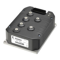
Curtis 1236 User Manual (137 pages)
INTEGRATED TRACTION & HYDRAULIC SYSTEM MOTOR CONTROLLER
Brand:
Curtis
| Category:
Controller
| Size: 3.88 MB
Table of Contents
Table of Contents
3
Figures
4
Tables
4
1 Overview
5
2 Installation and Wiring
7
Mounting the Controller
7
Dimensions in Millimeters (and Inches)
7
Lug Assembly
9
High Current Wiring Recommendations
9
Battery Cables (B+, B-)
9
High Current Connections and Wiring Guidelines
9
Table 1 High Current Connections
9
Low Current Wiring Recommendations
10
Motor Encoder (Pins 31, 32)
10
Motor Wiring (U, V, W)
10
Low Current Connections and Wiring Guidelines
10
Table 2 Low Current Connections
11
Controller Wiring: Basic Configuration
14
FIG . 3: Basic Wiring Diagram
14
Switch Input Wiring
15
Throttle Wiring
15
Throttle Type 2
16
FIG . 4: Wiring for Type 1 Throttles
16
Voltage Source
17
Current Source
17
3-Wire Potentiometer
17
Curtis ET-XXX Electronic Throttle
17
FIG . 5: Wiring for Type 2 Throttles
17
Throttle Type 4
18
Throttle Type 5
18
FIG . 6: Wiring for Type 3 Throttles
18
Input/Output Signal Specifications
20
Digital Inputs
20
Digital Input Specifications
20
Digital Outputs
21
Digital Output Specifications
21
Analog Inputs
22
Analog Input Specifications
22
Analog Output Specifications
22
Power Supply Output Specifications
22
KSI and Coil Return
23
Ksi and Coil Return Input Specifications
23
Throttle Input Specifications
23
Communications Ports
24
Encoder Inputs
24
3 Programmable Parameters
25
Programming Menus
25
Motor Response Tuning
25
Programmable Parameter Menus: 1311 Programmer
26
TABLE 3: Programmable Parameter Menus
26
Control Mode Select
29
Electrical Frequency Constraint
29
Encoder Pulses/Revolution Constraint
29
Motor Speed Constraints
29
Speed Mode Express Menu
30
Velocity Feedforward Menu
31
Acceleration Feedforward Menu
32
Fig. 7 Acceleration Response Rate Diagram
33
Response Menu
33
Fig. 8 Braking Response Rate Diagram
34
Fine Tuning Menu
34
Speed Limiter Menu
35
Fig. 9 Throttle Mapping (Torque Control Mode)
38
Fig. 10 Effect of Gear Soften Parameter (Torque Control Mode)
38
Fig. 11 Effect of Brake Taper Speed Parameter (Torque Control Mode)
38
Restraint Menu
39
Position Hold Menu
39
Current Limits Menu
40
Power Limiting Map Menu
41
Drive Limiting Map Menu
41
FIG . 12: Drive Current Limiting Map
41
Regen Limiting Map Menu
42
FIG . 13: Regen Current Limiting Map
42
Throttle Menu
43
Em Brake Control Menu
46
Main Contactor Menu
48
Proportional Driver Menu
50
Fault Checking Menu
51
Motor Menu
52
Motor Temperature Control Menu
53
Hydraulic Operation
54
Alternative Hydraulic System, Without Proportional Lowering
54
Fig. 15 Hydraulic System Diagram
54
FIG . 16: Alternative Hydraulic System
54
Hydraulics Menu
55
Hydraulic Throttle Menu
57
Battery Menu
59
BDI Algorithm
60
Vehicle Menu
62
Emergency Reverse Menu
63
Interlock Braking Menu
64
Can Interface Menu
65
Motor Characterization Tests Menu
66
Field Weakening Control Menu
66
Motor Type Parameter
66
Cloning
67
4A. MONITOR MENU
68
4B. CONTROLLER INFORMATION MENU
78
5 Initial Setup
79
Before You Start
79
Motor Temperature Sensor
80
Current Limits
80
Battery
80
Main Contactor
80
Faults
81
Setting Encoder Direction and Direction of Rotation
81
Motor Characterization
82
Emergency Reverse
82
Interlock Braking
82
Setting up the Hydraulic System
83
Hydraulic Throttle Inputs
83
Load Hold Valve
83
Proportional Lowering Valve
83
Adjustments
84
6 Tuning Guide
85
Selecting the Control Mode
85
Speed Mode Express
85
Speed Mode
86
Torque Mode
88
Vehicle Control Language (Vcl)
89
Summary of VCL Basics
89
Variable Types
90
Vcl Runtime Rates
92
I/O Control with Vcl
92
Driver and Digital Outputs
93
Potentiometer Inputs
94
Interfacing the Throttle and Brake Commands
96
Analog Output
96
Throttle Processing
96
Motor Command Diagram, AC Traction Motor
97
Brake Processing
99
Control Mode Processing
99
Hydraulic Throttle Processing
101
Vcl
103
Interfacing the Proportional Current Driver
104
Using the Fault Handler in Vcl
105
Additional Vcl Functions
110
Enable_Precharge
110
Disable_Precharge
111
Set_Digout
112
Clear_Digout
112
Enable_Emer_Rev
113
Disable_Emer_Rev
113
Set_Interlock
114
Clear_Interlock
114
Setup_Pot_Faults
115
8 Diagnostics and Troubleshooting
116
Summary of LED Display Formats
117
Troubleshooting
117
Table 4 TYPES of LED DISPLAY
117
Table 5 TROUBLESHOOTING CHART
118
9 Maintenance
126
Cleaning
126
Fault History
126
Theory of Operation
127
Motor Control Algorithms
127
Power Section
128
FIG . A-2: Power Section Topology
129
Electromagnetic Compatibility (Emc)
130
Immunity
130
Electrostatic Discharge (Esd)
132
Programming Devices
135
Handheld Programmer (1313)
135
Programmer Functions
135
Specifications
136
Advertisement
Advertisement
Related Products
Curtis 1236E
Curtis 1236SE
Curtis 1232E
Curtis 1234E
Curtis 1238E
Curtis 1234SE
Curtis 1232SE
Curtis 1238SE
Curtis 1239E
Curtis 1234
Curtis Categories
Coffee Maker
DVD Player
LCD TV
MP3 Player
Stereo System
More Curtis Manuals
Login
Sign In
OR
Sign in with Facebook
Sign in with Google
Upload manual
Upload from disk
Upload from URL