Table of Contents
Advertisement
Quick Links
Advertisement
Table of Contents

Related Manuals for Automationdirect.com DL305


Summary of Contents for Automationdirect.com DL305
- Page 1 DL305 Analog I/O Modules Manual Number D3--ANLG-M...
- Page 2 1--770--844--4200 or FAX 1--770--886--3199. This publication is based on information that was available at the time it was printed. At Automationdirect.comä we constantly strive to improve our products and services, so we reserve the right to make changes to the products and/or publications at any time without notice and without any obligation.
- Page 3 Manual Revisions If you contact us in reference to this manual, be sure to include the revision number. Title: DL305 Analog I/O Modules, 2nd Edition, Rev. C Manual Number: D3--ANLG--M Issue Date Effective Pages Description of Changes Original 1/94 Cover/Copyright...
- Page 4 1--3 DL305 Analog Components ............
-
Page 5: Table Of Contents
Table of Contents External Power Source ............. 1--10 Base Power Required . - Page 6 Table of Contents Module Operation ..............3- -8 Channel Scanning Sequence .
- Page 7 Table of Contents Connecting the Field Wiring ............5- -6 Wiring Guidelines .
- Page 8 Table of Contents Selecting Output Signal Ranges ........... . . 7--3 Connecting the Field Wiring .
- Page 9 Table of Contents Chapter 9: F3--08THM--n 8-Channel Thermocouple Input Introduction ............... . . 9- -2 Automatic Conversion .
- Page 10 ......... . . 10--17 Appendix A: DL305 Data Types and Memory Map DL330 Memory Map .
- Page 11 Getting Started In This Chapter..— Introduction — Physical Characteristics — Analog Input Terminology — Analog Output Module Terminology — Selecting the Appropriate Module — Analog Made Easy - - Four Simple Steps...
- Page 12 This manual is not intended to be a tutorial on analog signal theory, but rather, a user reference manual for the DL305 Analog I/O modules. If you have purchased operator interfaces or DirectSOFT...
- Page 13 8 channel temperature input module. Provides ladder logic examples for all bases and CPUs. Appendices Additional reference information on the DL305 analog modules is in the following five appendices: Reference A -- DL305C Data Types and Memory Map...
- Page 14 Getting Started DL305 Analog Components There are a wide variety of Analog I/O modules available for use with the DL305 family of automation products. These modules are well suited for monitoring and controlling various types of analog signals such as pressure, temperature, etc.
- Page 15 Getting Started Physical Characteristics The DL305 Analog Modules provide many features that make the modules easier to use. For example, the terminal block can be removed making wiring a simple task. You can also use our DINnector product line to organize your wiring even further (see our catalog for details).
- Page 16 1- -6 Getting Started Selecting the Appropriate Module The following tables provide a condensed version of the information you need to select the appropriate module. The most important thing is to simply determine the number of channels required and the signal ranges that must be supported. Once you’ve determined these parameters, look in the specific chapter for the selected module to determine the installation and operation requirements.
- Page 17 1- -7 Getting Started Analog Output Specification D3- -02DA FACTS F3- -04DA- -1 FACTS F3- -04DAS Channels Output Ranges 1 -- 10VDC 0 -- 5V 0 -- 5V 4 -- 20 mA 0 --10V 0 -- 10V 4 -- 12mA ? 5V 4 -- 20mA ? 10V...
- Page 18 1- -8 Getting Started Analog Made Easy - - Four Simple Steps Once you’ve selected the appropriate module, use the chapter that describes the module and complete the following steps. STEP 1. Take a minute to review the detailed specifications to make sure the module meets your application requirements.
- Page 19 1- -9 Getting Started Analog Input Terminology We use several different terms throughout the rest of this manual. You don’t have to be an expert on analog terms to use the products, but it may help make it easier to select the appropriate modules if you take a few minutes to review these definitions.
-
Page 20: External Power Source
1- -10 Getting Started Analog Output Module Terminology Channels per The number of analog channels or points available in the module to connect to field Module devices. Output Ranges The output ranges in voltage and/or current modes the module will operate properly within. -
Page 21: Module Specifications
D3- -04AD 4-Channel Analog Input In This Chapter..— Module Specifications — Setting the Module Jumpers — Connecting the Field Wiring — Module Operation — Writing the Control Program... - Page 22 Common mode: 60dB/60Hz (--5 to 10V) Analog Input The D3--04AD Analog Input appears as a 16-point module. The module can be installed in any slot configured for 16 points. See the DL305 User Manual for details Configuration Requirements on using 16 point modules in DL305 systems. The limitation on the number of analog...
-
Page 23: Wiring Guidelines
Check local and national codes to choose the correct method for your application. User Power Supply The D3--04AD requires a separate power supply. The DL305 bases have built-in 24 Requirements VDC power supplies that provide up to 100 mA of current. If you only have one analog module, you can use this power source instead of a separate supply. -
Page 24: Custom Input Ranges
2- -4 D3--04AD 4-Channel Analog Input Custom Input Occasionally you may have the need to connect a transmitter with an unusual signal Ranges range. By changing the wiring slightly and adding an external resistor to convert the current to voltage, you can easily adapt this module to meet the specifications for a transmitter that does not adhere to one of the standard input ranges. -
Page 25: Current Loop Transmitter Impedance
2- -5 D3--04AD 4-Channel Analog Input Current Loop Standard 4 to 20 mA transmitters and transducers can operate from a wide variety of Transmitter power supplies. Not all transmitters are alike and the manufacturers often specify a Impedance minimum loop or load resistance that must be used with the transmitter. The D3--04AD provides 250 ohm resistance for each channel. -
Page 26: Removable Connector
2- -6 D3--04AD 4-Channel Analog Input Removable The D3--04AD module has a removable connector to make wiring easier. Simply Connector squeeze the tabs on the top and bottom and gently pull the connector from the module. Wiring Diagram Note 1: Terminate all shields of the cable at their respective signal source. -
Page 27: Module Operation
2- -7 D3--04AD 4-Channel Analog Input Module Operation Before you begin writing the control program, it is important to take a few minutes to understand how the module processes and represents the analog signals. Channel Scanning The D3--04AD module supplies 1 channel of data per each CPU scan. Since there Sequence are four channels, it can take up to four scans to get data for all channels. -
Page 28: Understanding The I/O Assignments
2- -8 D3--04AD 4-Channel Analog Input Understanding the You may recall the D3--04AD module appears to the CPU as a 16-point module. I/O Assignments Some of the points are inputs to the CPU and some are outputs to the module. These 16 points provide: an indication of which channel is active. -
Page 29: Single Channel Scan Outputs
2- -9 D3--04AD 4-Channel Analog Input Single Channel The upper register also contains two Scan Outputs additional outputs that can be used to R011 choose a single channel for scanning. These outputs are ignored if the channel scan output is turned on. (Note, our example shows outputs 114 and 115. -
Page 30: Analog Data Bits
2- -10 D3--04AD 4-Channel Analog Input Analog Data Bits The first register contains 8 bits which represent the analog data in binary R001 format. Value Value - - analog data bits Since the module has 8-bit resolution, the analog signal is converted into 256 “pieces”... -
Page 31: Writing The Control Program
This rung loads the data into the accumulator on DSTR1 every scan. (You can use any permissive contact.) R001 The DL305 CPUs perform math operations in BCD. This instruction converts the binary data to BCD. (You can omit this step if your application does not require the conversion.) - Page 32 This rung loads the data into the accumulator. This DSTR1 rung executes for all channels. R001 The DL305 performs math operations in BCD. This instruction converts the binary data to BCD. (You can omit this step if your application does not require the data in BCD format.)
-
Page 33: Single Or Multiple Channels
R001 channel scan. The DL305 performs math operations in BCD. This instruction converts the binary data to BCD. (You can omit this step if your application does not require the data in BCD format.) - Page 34 2- -14 D3--04AD 4-Channel Analog Input Scaling the Input Most applications usually require Data measurements in engineering units, Units = (A/256)*S which provide more meaningful data. This is accomplished by using the Units = value in Engineering Units conversion formula shown. A = Analog value (0 -- 255) S = high limit of the Engineering unit range...
- Page 35 2- -15 D3--04AD 4-Channel Analog Input The following instructions are required to scale the data. We’ll continue to use the 42.9 PSI example. In this example we’re using channel 1. Input 110 is the active channel indicator for channel 1. Of course, if you were using a different channel, you would use the active channel indicator point that corresponds to the channel you were using.
- Page 36 2- -16 D3--04AD 4-Channel Analog Input You probably noticed that the previous example yielded 42 PSI when the real value should have been 42.9 PSI. By changing the scaling value slightly, we can “imply” an extra decimal of precision. Notice in the following example we’ve added another digit to the scale.
- Page 37 This rung loads the data into the accumulator on DSTR1 every scan. (You could use any permissive contact.) R001 The DL305 CPUs perform math operations in BCD. Since we will perform math on the data, the data must be converted from binary data to BCD. Store channel 1 The analog value is divided by the resolution of the module, stored in R430.
-
Page 38: Analog And Digital Value Conversions
2- -18 D3--04AD 4-Channel Analog Input Analog and Digital Sometimes it is helpful to be able to quickly convert between the signal levels and the Value Conversions digital values. This is especially helpful during machine startup or troubleshooting. The following table provides formulas to make this conversion easier. Range If you know the digital value ... -
Page 39: Module Specifications
F3- -04ADS 4-Channel Isolated Analog Input In This Chapter..— Module Specifications — Setting the Module Jumpers — Connecting the Field Wiring — Module Operation — Writing the Control Program... - Page 40 NEMA ICS3--304 Analog Input The F3--04ADS Analog Input appears as a 16-point module. The module can be installed in any slot configured for 16 points. See the DL305 User Manual for details Configuration Requirements on using 16 point modules in DL305 systems. The limitation on the number of analog...
-
Page 41: Jumper Locations
3- -3 F3--04ADS 4-Channel Isolated Analog Input Setting the Module Jumpers Jumper Locations The module is set at the factory for a 4--20 mA signal on all four channels. If this is acceptable you do not have to change any of the jumpers. The following diagram shows how the jumpers are set. - Page 42 3- -4 F3--04ADS 4-Channel Isolated Analog Input Selecting Input As you examin the jumper settings, notice there are jumpers for each individual Signal Ranges channel. These jumpers allow you to select the type of signal (voltage or current) and the range of the signal. The following tables show the jumper selections for the various ranges.
-
Page 43: Connecting The Field Wiring
3- -5 F3--04ADS 4-Channel Isolated Analog Input Connecting the Field Wiring Wiring Guidelines Your company may have guidelines for wiring and cable installation. If so, you should check those before you begin the installation. Here are some general things to consider. -
Page 44: Current Loop Transmitter Impedance
3- -6 F3--04ADS 4-Channel Isolated Analog Input Current Loop Standard 4 to 20 mA transmitters and transducers can operate from a wide variety of Transmitter power supplies. Not all transmitters are alike and the manufacturers often specify a Impedance minimum loop or load resistance that must be used with the transmitter. The F3--04ADS provides 250 ohm resistance for each channel. -
Page 45: Removable Connector
3- -7 F3--04ADS 4-Channel Isolated Analog Input Removable The F3--04ADS module has a removable connector to make wiring easier. Simply Connector squeeze the top and bottom tabs and gently pull the connector from the module. Wiring Diagram Note 1: Connect unused voltage or current inputs to 0VDC at terminal block or leave current jumper installed (see Channel 3). -
Page 46: Module Operation
3- -8 F3--04ADS 4-Channel Isolated Analog Input Module Operation Before you begin writing the control program, it is important to take a few minutes to understand how the module processes and represents the analog signals. Channel Scanning The F3--04ADS module supplies1 channel of data per each CPU scan. Since there Sequence are four channels, it can take up to four scans to get data for all channels. -
Page 47: Understanding The I/O Assignments
3- -9 F3--04ADS 4-Channel Isolated Analog Input Understanding the You may recall the F3--04ADS module appears to the CPU as a 16-point module. I/O Assignments These 16 points provide: an indication of which channel is active. the digital representation of the analog signal. Since all I/O points are automatically mapped into Register (R) memory, it is very easy to determine the location of the data word that will be assigned to the module. -
Page 48: Analog Data Bits
3- -10 F3--04ADS 4-Channel Isolated Analog Input Analog Data Bits The remaining twelve bits represent the analog data in binary format. R011 R001 Value Value 0 (LSB) 1024 - - data bits 2048 Since the module has 12-bit resolution, the analog signal is converted into 4096 “pieces”... -
Page 49: Writing The Control Program
This rung loads the data into the accumulator on DSTR1 every scan. (You can use any permissive contact.) R001 The DL305 CPUs perform math operations in BCD. This instruction converts the binary data to BCD. (You can omit this step if your application does not require the conversion.) - Page 50 Alternating Scans can perform math on the data, compare the data against preset values, etc. Since the DL305 CPUs use 8-bit word instructions, you have to move the data in pieces. It’s simple if you follow the example. Read the data...
- Page 51 3- -13 F3--04ADS 4-Channel Isolated Analog Input Reading Multiple The example below shows how to scale input data from an F3--04ADS Analog Channels over module in the X0 position of the D3--XX--1 base. This module must be placed in a 16 Alternating Scans bit slot in order to work.
- Page 52 3- -14 F3--04ADS 4-Channel Isolated Analog Input Scaling the Input Most applications usually require Units = Data measurements in engineering units, 4096 which provide more meaningful data. This is accomplished by using the Units = value in Engineering Units conversion formula shown. A = Analog value (0 -- 4095) S = high limit of the Engineering unit range...
- Page 53 3- -15 F3--04ADS 4-Channel Isolated Analog Input The following instructions are required to scale the data. We’ll continue to use the 42.9 PSI example. In this example we’re using channel 1. Input 114 is the active channel indicator for channel 1. Of course, if you were using a different channel, you would use the active channel indicator point that corresponds to the channel you were using.
- Page 54 3- -16 F3--04ADS 4-Channel Isolated Analog Input You probably noticed the previous example yielded 42 PSI when the real value should have been 42.9 PSI. By changing the scaling value slightly, we can “imply” an extra decimal of precision. Notice in the following example we’ve added another digit to the scale.
- Page 55 3- -17 F3--04ADS 4-Channel Isolated Analog Input This example program shows how you can use the instructions to load these equation constants into data registers. The example is written for channel 1, but you can easily use a similar approach to use different scales for all channels if required. You may just use the appropriate constants in the instructions dedicated for each channel, but this method allows easier modifications.
- Page 56 20--27/120--127 address slot. This module must be placed in a 16 bit Conventional slot in order to work. DL305 Base Load the data This loads the upper byte of the analog data from X120 the module.
-
Page 57: Analog And Digital Value Conversions
3- -19 F3--04ADS 4-Channel Isolated Analog Input Analog and Digital Sometimes it is helpful to be able to quickly convert between the signal levels and the Value Conversions digital values. This is especially helpful during machine startup or troubleshooting. The following table provides formulas to make this conversion easier. Range If you know the digital value ... -
Page 58: Module Specifications
F3- -08AD 8-Channel Analog Input In This Chapter..— Module Specifications — Setting the Module Jumpers — Connecting the Field Wiring — Module Operation — Writing the Control Program... - Page 59 The F3--08AD Analog Input appears as a 16-point module. The module can be Configuration installed in any slot configured for 16 points. See the DL305 User Manual for details on using 16 point modules in DL305 systems. The limitation on the number of analog...
-
Page 60: Jumper Locations
4- -3 F3--08AD 8-Channel Analog Input Setting the Module Jumpers Jumper Locations The module is set at the factory for a 4--20 mA signal on all eight channels. If this is acceptable you do not have to change any of the jumpers. The following diagram shows how the jumpers are set. -
Page 61: Connecting The Field Wiring
4- -4 F3--08AD 8-Channel Analog Input Connecting the Field Wiring Wiring Guidelines Your company may have guidelines for wiring and cable installation. If so, you should check those before you begin the installation. Here are some general things to consider. Use the shortest wiring route whenever possible. -
Page 62: Removable Connector
4- -5 F3--08AD 8-Channel Analog Input Removable The F3--08AD module has a removable connector to make wiring easier. Simply Connector squeeze the top and bottom tabs and gently pull the connector from the module. Wiring Diagram Note 1: Terminate all shields at their respective signal source Note 2: To avoid “ground loop”... -
Page 63: Module Operation
4- -6 F3--08AD 8-Channel Analog Input Module Operation Before you begin writing the control program, it is important to take a few minutes to understand how the module processes and represents the analog signals. Channel Scanning The F3--08AD module supplies1 channel of data per each CPU scan. Since there Sequence are eight channels, it can take up to eight scans to get data for all channels. -
Page 64: Understanding The I/O Assignments
4- -7 F3--08AD 8-Channel Analog Input Understanding the You may recall the F3--08AD module appears to the CPU as a 16-point module. I/O Assignments These 16 points provide: an indication of which channel is active. the digital representation of the analog signal. Since all I/O points are automatically mapped into Register (R) memory, it is very easy to determine the location of the data word that will be assigned to the module. -
Page 65: Analog Data Bits
4- -8 F3--08AD 8-Channel Analog Input Analog Data Bits The remaining twelve bits represent the analog data in binary format. R011 R001 Value Value 0 (LSB) 1024 - - data bits 2048 Since the module has 12-bit resolution, 4 - - 20mA the analog signal is converted into 4096 “pieces”... -
Page 66: Writing The Control Program
This rung loads the data into the accumulator on DSTR1 every scan. (You can use any permissive contact.) R001 The DL305 CPUs perform math operations in BCD. This instruction converts the binary data to BCD. (You can omit this step if your application does not require the conversion.) - Page 67 Alternating Scans can perform math on the data, compare the data against preset values, etc. Since the DL305 CPUs use 8-bit word instructions, you have to move the data in pieces. It’s simple if you follow the example. Read the data...
- Page 68 DL350 with a Load the data Conventional DL305 Base X120 This rung loads the upper byte of analog data from the module. SHFL K8 shifts the data to the left eight places to SHFL make room for the lower byte of data.
- Page 69 4- -12 F3--08AD 8-Channel Analog Input Channel 4 Select Bit States X124 X125 X126 This writes channel four analog data to V3003 when bits X124, X125 and X126 are as shown. V3003 Channel 5 Select Bit States X124 X125 X126 This writes channel five analog data to V3004 when bits X124, X125 and X126 are as shown.
- Page 70 4- -13 F3--08AD 8-Channel Analog Input Scaling the Input Most applications usually require Units = Data measurements in engineering units, 4096 which provide more meaningful data. This is accomplished by using the Units = value in Engineering Units conversion formula shown. A = Analog value (0 -- 4095) S = high limit of the Engineering unit range...
- Page 71 4- -14 F3--08AD 8-Channel Analog Input The following instructions are required to scale the data. We’ll continue to use the 42.9 PSI example. In this example we’re using channel 1. Input 114, input 115, and input 116 are all off when channel 1 data is being read. Of course, if you were using a different channel, you would use the active channel indicator point combination that corresponds to the channel you were using.
- Page 72 4- -15 F3--08AD 8-Channel Analog Input You probably noticed the previous example yielded 42 PSI when the real value should have been 42.9 PSI. By changing the scaling value slightly, we can “imply” an extra decimal of precision. Notice in the following example we’ve added another digit to the scale.
- Page 73 4- -16 F3--08AD 8-Channel Analog Input This example program shows how you can use the instructions to load these equation constants into data registers. The example was written for channel 1, but you could easily use a similar approach to use different scales for all channels if required.
- Page 74 20--27/120--127 address slot. This module must be placed in a 16 bit slot in Conventional order to work. DL305 Base Load the data This loads the upper byte of the analog data from X120 the module.
-
Page 75: Analog And Digital Value Conversions
4- -18 F3--08AD 8-Channel Analog Input Analog and Digital Sometimes it is helpful to be able to quickly convert between the signal levels and the Value Conversions digital values. This is especially helpful during machine startup or troubleshooting. The following table provides formulas to make this conversion easier. Range If you know the digital value ... -
Page 76: Module Specifications
F3- -16AD 16-Channel Analog Input In This Chapter..— Module Specifications — Setting the Module Jumpers — Connecting the Field Wiring — Module Operation — Writing the Control Program... - Page 77 2 -- resolution is 3275 counts (instead of 4096). Allows easier broken transmitter detection Analog Input The F3--16AD Analog Input appears as a 16-point module. The module can be installed in any slot configured for 16 points. See the DL305 User Manual for details Configuration Requirements on using 16 point modules in DL305 systems.
-
Page 78: Jumper Locations
5- -3 F3--16AD 16-Channel Analog Input Setting the Module Jumpers Jumper Locations The module is set at the factory for a 0--20 mA signal on all sixteen channels. If this is acceptable you do not have to change any of the jumpers. The following diagram shows the jumper locations. - Page 79 5- -4 F3--16AD 16-Channel Analog Input Selecting Input As you examined the jumper settings, you may have noticed there are current Signal Ranges jumpers for each individual channel. These jumpers allow you to select the type of signal (voltage or current). The span and polarity jumpers are used to select the signal range.
-
Page 80: Gain Jumpers
5- -5 F3--16AD 16-Channel Analog Input Gain Jumpers You do not have to change the Gain jumpers. These jumpers are installed to allow the ranges shown previously. Note, if you change these jumpers the module will not operate the way you expect. Variable Gain If you look at the terminal block closely, Potentiometer... -
Page 81: Connecting The Field Wiring
5- -6 F3--16AD 16-Channel Analog Input Connecting the Field Wiring Wiring Guidelines Your company may have guidelines for wiring and cable installation. If so, you should check those before you begin the installation. Here are some general things to consider. Use the shortest wiring route whenever possible. - Page 82 5- -7 F3--16AD 16-Channel Analog Input Custom Input Occasionally you may have the need to connect a transmitter with an unusual signal Ranges range. By changing the wiring slightly and adding an external resistor to convert the current to voltage, you can easily adapt this module to meet the specifications for a transmitter that does not adhere to one of the standard input ranges.
-
Page 83: Current Loop Transmitter Impedance
5- -8 F3--16AD 16-Channel Analog Input Current Loop Standard 4 to 20 mA transmitters and transducers can operate from a wide variety of Transmitter power supplies. Not all transmitters are alike and the manufacturers often specify a Impedance minimum loop or load resistance that must be used with the transmitter at the various voltages. -
Page 84: Removable Connector
5- -9 F3--16AD 16-Channel Analog Input Removable The F3--16AD module has a removable connector to make wiring easier. Simply Connector squeeze the top and bottom tabs and gently pull the connector from the module. Wiring Diagram Note 1: Terminate all shields at their respective signal source. Note 2: Jumpers for CH4, 7, 12 and 16 are installed for current input. -
Page 85: Module Operation
5- -10 F3--16AD 16-Channel Analog Input Module Operation Before you begin writing the control program, it is important to take a few minutes to understand how the module processes and represents the analog signals. Channel Scanning The F3--16AD module supplies 1 channel of data per each CPU scan. Since there Sequence are sixteen channels, it can take up to sixteen scans to get data for all channels. -
Page 86: Understanding The I/O Assignments
5- -11 F3--16AD 16-Channel Analog Input Understanding the You may recall the F3--16AD module appears to the CPU as a 16-point module. I/O Assignments These 16 points provide: an indication of which channel is active. the digital representation of the analog signal. Since all I/O points are automatically mapped into Register (R) memory, it is very easy to determine the location of the data word that will be assigned to the module. -
Page 87: Active Channel Indicator Inputs
5- -12 F3--16AD 16-Channel Analog Input Active Channel The last four inputs of the upper Register Indicator Inputs indicate active channel. R011 indicators automatically increment with each CPU scan. Channel Active Scan Inputs Channel 0000 0001 - - channel indicator inputs 0010 0011 0100... -
Page 88: Analog Data Bits
5- -13 F3--16AD 16-Channel Analog Input Analog Data Bits The remaining twelve bits represent the analog data in binary format. R011 R001 Value Value 0 (LSB) 1024 - - data bits 2048 Since the module has 12-bit resolution, the analog signal is converted into 4096 “pieces”... -
Page 89: Writing The Control Program
5- -14 F3--16AD 16-Channel Analog Input Writing the Control Program Identifying the Since all channels are multiplexed into a single data word, the control program must Data Locations be setup to determine which channel is being read. Since the module provides input points to the CPU, it is very easy to use the active channel status bits to determine which channel is being monitored. -
Page 90: Example Program
Register locations. Once the data is in a Register, you can perform math on the data, compare the data against preset values, etc. Since the DL305 CPUs use 8-bit word instructions, you have to move the data in pieces. It’s pretty simple if you follow the example. - Page 91 The example below shows how to read multiple channels on an F3--08AD Analog Conventional module in the 20--27/120--127 address slot. This module must be placed in a 16 bit DL305 Base slot in order to work. Load the data X120 This rung loads the upper byte of analog data from the module.
- Page 92 5- -17 F3--16AD 16-Channel Analog Input DL350 with a The example below shows how to read multiple channels on an F3--16AD Analog D3- -XX- -1 Base module in the X0 address of the D3--XX--1 base. This rung loads the upper byte of analog data from the module.
- Page 93 5- -18 F3--16AD 16-Channel Analog Input Channel Selection Data V1400 V1401 Channel #4 Data V2003 Channel Selection Data V1400 V1401 Channel #5 Data V2004 Channel Selection Data V1400 V1401 Channel #6 Data V2005 Channel Selection Data V1400 V1401 Channel #7 Data V2006 Channel Selection Data V1400...
- Page 94 5- -19 F3--16AD 16-Channel Analog Input Channel Selection Data V1400 V1401 Channel #11 Data V2012 Channel Selection Data V1400 V1401 Channel #12 Data V2013 Channel Selection Data V1400 V1401 Channel #13 Data V2014 Channel Selection Data V1400 V1401 Channel #14 Data V2015 Channel Selection Data V1400...
- Page 95 5- -20 F3--16AD 16-Channel Analog Input Scaling the Input Most applications usually require Units = Data measurements in engineering units, 4096 which provide more meaningful data. This is accomplished by using the Units = value in Engineering Units conversion formula shown. A = Analog value (0 -- 4095) S = high limit of the Engineering unit range...
- Page 96 5- -21 F3--16AD 16-Channel Analog Input The following instructions are required to scale the data. (We’ll continue to use the 42.9 PSI example.) In this example we’re using channel 1. The active channel indicator inputs are all off when channel 1 data is being read. Of course, if you were using a different channel, you would use the active channel indicator point combination that corresponds to the channel you were using.
- Page 97 5- -22 F3--16AD 16-Channel Analog Input You probably noticed the previous example yielded 42 PSI when the real value should have been 42.9 PSI. By changing the scaling value slightly, we can “imply” an extra decimal of precision. Notice in the following example we’ve added another digit to the scale.
- Page 98 5- -23 F3--16AD 16-Channel Analog Input This example program shows how you can use the instructions to load these equation constants into data registers. The example is written for channel 1, but you can easily use a similar approach to use different scales for all channels if required. You may just use the appropriate constants in the instructions dedicated for each channel, but this method allows easier modifications.
- Page 99 20--27/120--127 address slot. This module must be placed in a 16 bit Conventional slot in order to work. DL305 Base Load the data This loads the upper byte of the analog data from X120 the module.
-
Page 100: Broken Transmitter Detection
5- -25 F3--16AD 16-Channel Analog Input Broken Transmitter If you use 4--20mA signals you can easily check for broken transmitter conditions. Detection Since you have to use the 0--20mA range and the lowest signal for the 4--20mA transmitter is 4mA, the lowest digital value for the signal is not 0, but instead is 819. If the transmitter is working properly the smallest value you should ever see is 819. -
Page 101: Analog And Digital Value Conversions
5- -26 F3--16AD 16-Channel Analog Input Analog and Digital Sometimes it is helpful to be able to quickly convert between the signal levels and the Value Conversions digital values. This is especially helpful during machine startup or troubleshooting. The following table provides formulas to make this conversion easier. Range If you know the digital value ... -
Page 102: Module Specifications
D3- -02DA 2- -Channel Analog Output In This Chapter..— Module Specifications — Connecting the Field Wiring — Module Operation — Writing the Control Program... - Page 103 The D3--02DA Analog Output appears as a 16-point module. The module can be Configuration installed in any slot configured for 16 points. See the DL305 User Manual for details Requirements on using 16 point modules in DL305 systems. The limitation on the number of analog...
-
Page 104: Wiring Guidelines
6- -3 D3--02DA 2-Channel Analog Output Connecting the Field Wiring Wiring Guidelines Your company may have guidelines for wiring and cable installation. If so, you should check those before you begin the installation. Here are some general things to consider. Use the shortest wiring route whenever possible. -
Page 105: Removable Connector
6- -4 D3--02DA 2-Channel Analog Output Removable The D3--02DA module has a removable connector to make wiring easier. Simply Connector remove the retaining screws and gently pull the connector from the module. Wiring Diagram Note 1: Shields should be connected to the 0V of the module or to the 0V of the P/S. -
Page 106: Module Operation
6- -5 D3--02DA 2-Channel Analog Output Module Operation Before you begin writing the control program, it is important to take a few minutes to understand how the module processes and represents the analog signals. Channel Scanning The D3--02DA module updates both channels in the same scan. The control Sequence program updates the two channels of this module independent of each other and each channel does not have to be refreshed on each scan. -
Page 107: Understanding The I/O Assignments
6- -6 D3--02DA 2-Channel Analog Output Understanding the You may recall the D3--02DA module appears to the CPU as a 16-point module. I/O Assignments These 16 points provide the digital representation of the analog signal. Since all I/O points are automatically mapped into Register (R) memory, it is very easy to determine the location of the data word that will be assigned to the module. -
Page 108: Analog Data Bits
6- -7 D3--02DA 2-Channel Analog Output Analog Data Bits The first register contains the data for channel one (R001). The second register R001 contains the data for channel two (R011). Value Value - - analog data bits Since the module has 8-bit resolution, the analog signal is converted into 256 “pieces”... -
Page 109: Writing The Control Program
6- -8 D3--02DA 2-Channel Analog Output Writing the Control Program Identifying the As mentioned earlier, you can update either channel or both channels during the Data Locations same scan. Since the module does not have any channel select bits, you just simply determine the location of the data word and send the data word to the output module whenever you need to update the data. - Page 110 6- -9 D3--02DA 2-Channel Analog Output Here’s how you would write the program to perform the Engineering Unit conversion. This example assumes you have calculated or loaded the engineering unit value and stored it in R400. Also, you have to perform this for both channels if you’re using different data for each channel.
- Page 111 6- -10 D3--02DA 2-Channel Analog Output There will probably be times when you need more precise control. For example, maybe your application requires 42.9 PSI, not just 42 PSI. By changing the scaling value slightly, we can “imply” an extra decimal of precision. Notice in the following example we’ve entered 429 as the Engineering unit value and we’ve added another digit to the scale.
- Page 112 6- -11 D3--02DA 2-Channel Analog Output Sending the Same In some applications, you’ll want to send the same output values to both channels. Data to Both The following program example shows how to send the digital values to the module. Channels This example assumes you have already loaded the Engineering unit value in R450 and R451.
- Page 113 6- -12 D3--02DA 2-Channel Analog Output Sending Specific In this case, the example logic is setup to send different data to each channel. Of Data to Each course, you would have to have separate routines to calculate the output data and Channel you would have to store the different values in separate registers.
-
Page 114: Analog And Digital Value Conversions
6- -13 D3--02DA 2-Channel Analog Output Analog and Digital Sometimes it is helpful to be able to quickly convert between the voltage or current Value Conversions signal levels and the digital values. This is especially helpful during machine startup or troubleshooting. The following table provides formulas to make this conversion easier. -
Page 115: Module Specifications
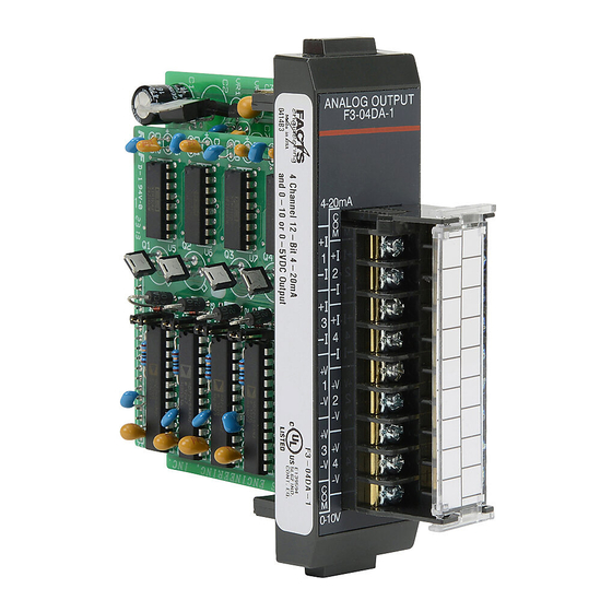
F3- -04DA- -1 4-Channel Analog Output In This Chapter..— Module Specifications — Setting the Module Jumpers — Connecting the Field Wiring — Module Operation — Writing the Control Program... - Page 116 The F3--04DA--1 Analog Output appears as a 16-point module. The module can be Configuration installed in any slot configured for 16 points. See the DL305 User Manual for details Requirements on using 16 point modules in DL305 systems. The limitation on the number of analog...
- Page 117 7- -3 F3--04DA--1 4-Channel Analog Output Setting the Module Jumpers Jumper Locations The module is set at the factory for a 0--10V signal on all four channels. (This range also allows 4--20 mA operation since there are separate I and V wiring terminals.) If this is acceptable you do not have to change any of the jumpers.
-
Page 118: Wiring Guidelines
7- -4 F3--04DA--1 4-Channel Analog Output Connecting the Field Wiring Wiring Guidelines Your company may have guidelines for wiring and cable installation. If so, you should check those before you begin the installation. Here are some general things to consider. Use the shortest wiring route whenever possible. -
Page 119: Removable Connector
7- -5 F3--04DA--1 4-Channel Analog Output Removable The F3--04DA--1 module has a removable connector to make wiring easier. Simply Connector squeeze the top and bottom tabs and gently pull the connector from the module. Wiring Diagram Note 1: Shields should be connected to the 0V (COM) ANALOG OUTPUT of the module F3--04DA--1... -
Page 120: Module Operation
7- -6 F3--04DA--1 4-Channel Analog Output Module Operation Before you begin writing the control program, it is important to take a few minutes to understand how the module processes and represents the analog signals. Channel Scanning The F3--04DA--1 module can update one channel per CPU scan. Your RLL program Sequence selects which channel to update, so you have complete flexibility to solve your application requirements. -
Page 121: Understanding The I/O Assignments
7- -7 F3--04DA--1 4-Channel Analog Output Understanding the You may recall the F3--04DA--1 module appears to the CPU as a 16-point module. I/O Assignments These 16 points provide: the digital representation of the analog signal. identification of the channel to receive the data. Since all I/O points are automatically mapped into Register (R) memory, it is very easy to determine the location of the data word that will be assigned to the module. - Page 122 7- -8 F3--04DA--1 4-Channel Analog Output Analog Data Bits The remaining twelve bits represent the analog data in binary format. R011 R001 Value Value 0 (LSB) 1024 - - data bits 2048 Since the module has 12-bit resolution, the analog signal is converted into 4096 “pieces”...
-
Page 123: Writing The Control Program
7- -9 F3--04DA--1 4-Channel Analog Output Writing the Control Program Identifying the As mentioned earlier, you can use the channel selection bits to determine which channels will be updated. The following diagram shows the location for both the Data Locations channel selection bits and data bits. - Page 124 7- -10 F3--04DA--1 4-Channel Analog Output Here’s how you would write the program to perform the Engineering unit conversion. This example assumes you have calculated or loaded the engineering unit value and stored it in R400. Also, you have to perform this for all channels if you’re using different data for each channel.
- Page 125 7- -11 F3--04DA--1 4-Channel Analog Output There will probably be times when you need more precise control. For example, maybe your application requires 42.9 PSI, not just 42 PSI. By changing the scaling value slightly, we can “imply” an extra decimal of precision. Notice in the following example we’ve entered 429 as the Engineering unit value and we’ve added another digit to the scale.
- Page 126 7- -12 F3--04DA--1 4-Channel Analog Output Sending Data to a The following program example shows how to send the digital value to a single Single Channel channel. This example assumes you have already loaded the Engineering unit value in R450 and R451. Send Channel 1 This rung loads the data into the accumulator on DSTR...
-
Page 127: Sequencing The Channel Updates
7- -13 F3--04DA--1 4-Channel Analog Output Sequencing the This example shows how to send digital values to the module when you have more Channel Updates than one channel. This example will automatically update all four channels over four scans. The example is fairly simple and will work in most all situations, but there are instances where problems can occur. -
Page 128: Analog And Digital Value Conversions
7- -14 F3--04DA--1 4-Channel Analog Output Analog and Digital Sometimes it is helpful to be able to quickly convert between the voltage or current Value Conversions signal levels and the digital values. This is especially helpful during machine startup or troubleshooting. The following table provides formulas to make this conversion easier. -
Page 129: Module Specifications
F3- -04DAS 4-Channel Isolated Analog Output In This Chapter..— Module Specifications — Setting the Module Jumpers — Connecting the Field Wiring — Module Operation — Writing the Control Program... - Page 130 8- -2 F3--04DAS 4-Channel Isolated Analog Output Module Specifications The following table provides the specifications for the F3--04DAS Analog Output Module. Review these specifications to make sure the module meets your application requirements. Number of Channels Output Ranges ? 5V, ? 10V, 0--5V, 0--10V, 1--5V, 0--20 mA, 4--20 mA Resolution 12 bit (1 in 4096)
- Page 131 16 points, but should not be installed in Slot 3 of Requirements any DL305 base. See the DL305 User Manual for details on using 16 point modules in DL305 systems. The limitation on the number of analog modules are: For local and expansion systems, the available power budget and 16-point module usage are the limiting factors.
- Page 132 8- -4 F3--04DAS 4-Channel Isolated Analog Output Setting the Module Jumpers Jumper Locations The module is set at the factory for a 0--10V signal on all four channels. If this is acceptable you do not have to change any of the jumpers. If you examine the top board on the module you will notice four sets of jumpers.
- Page 133 8- -5 F3--04DAS 4-Channel Isolated Analog Output Selecting Input The following tables show the jumper selections for the various ranges. (Only Signal Ranges channel 1 is used in the example, but all channels must be set.) Bipolar Signal Range Jumper Settings --5 VDC to +5 VDC Channel 1 (JP4) Offset Jumper (JP1)
- Page 134 8- -6 F3--04DAS 4-Channel Isolated Analog Output Special Output The following tables show the jumper selections for some additional ranges that are Signal Ranges not normally found in many applications. Notice you can install or remove the offset jumper to change the settings. (Only channel 1 is used in the example, but all channels must be set.) Signal Range Signal Range...
-
Page 135: Wiring Guidelines
8- -7 F3--04DAS 4-Channel Isolated Analog Output Connecting the Field Wiring Wiring Guidelines Your company may have guidelines for wiring and cable installation. If so, you should check those before you begin the installation. Here are some general things to consider. -
Page 136: Removable Connector
8- -8 F3--04DAS 4-Channel Isolated Analog Output Removable The F3--04DAS module has a removable connector to make wiring easier. Simply Connector squeeze the top and bottom tabs and gently pull the connector from the module. Wiring Diagram Note1: Shields should be connected to the respective channel’s -- V terminal of the module. -
Page 137: Combining Current Outputs
8- -9 F3--04DAS 4-Channel Isolated Analog Output Combining Current You cannot connect the current outputs in series (like the voltage outputs) but you Outputs can achieve unusual ranges with a few wiring and programming tricks. For example, let’s say an application requires a ? 20 mA range. By completing the following steps, you could easily accommodate this requirement. -
Page 138: Module Operation
8- -10 F3--04DAS 4-Channel Isolated Analog Output Module Operation Before you begin writing the control program, it is important to take a few minutes to understand how the module processes and represents the analog signals. Channel Scanning The F3--04DAS module can update one channel per CPU scan. Your RLL program Sequence selects the channel to update, so you have complete flexibility in solving your application requirements. -
Page 139: Understanding The I/O Assignments
8- -11 F3--04DAS 4-Channel Isolated Analog Output Understanding the You may recall the F3--04DAS module appears to the CPU as a 16-point module. I/O Assignments These 16 points provide: the digital representation of the analog signal. identification of the channel to receive the data. Since all I/O points are automatically mapped into Register (R) memory, it is very easy to determine the location of the data word that will be assigned to the module. -
Page 140: Analog Data Bits
8- -12 F3--04DAS 4-Channel Isolated Analog Output Analog Data Bits The remaining twelve bits represent the analog data in binary format. R011 R001 Value Value 0 (LSB) 1024 - - data bits 2048 Since the module has 12-bit resolution, the analog signal is converted into 4096 “pieces”... -
Page 141: Writing The Control Program
8- -13 F3--04DAS 4-Channel Isolated Analog Output Writing the Control Program Identifying the As mentioned earlier, you can use the channel selection bits to determine which Data Locations channels will be updated. The following diagram shows the location for both the channel selection bits and data bits. - Page 142 8- -14 F3--04DAS 4-Channel Isolated Analog Output Here’s how you would write the program to perform the Engineering Unit conversion. This example assumes you have calculated or loaded the engineering unit value and stored it in R400. Also, you have to perform this for all channels if you’re using different data for each channel.
- Page 143 8- -15 F3--04DAS 4-Channel Isolated Analog Output There will probably be times when you need more precise control. For example, maybe your application requires 42.9 PSI, not just 42 PSI. By changing the scaling value slightly, we can “imply” an extra decimal of precision. Notice in the following example we’ve entered 429 as the Engineering unit value and we’ve added another digit to the scale.
- Page 144 8- -16 F3--04DAS 4-Channel Isolated Analog Output Sending Data to a The following program example shows how to send the digital value to a single Single Channel channel. This example assumes you have already loaded the Engineering unit value in R450 and R451. Send Channel 1 This rung loads the data into the accumulator on DSTR...
-
Page 145: Sequencing The Channel Updates
8- -17 F3--04DAS 4-Channel Isolated Analog Output Sequencing the This example shows how to send digital values to the module when you have more Channel Updates than one channel. This example will automatically update all four channels over four scans. The example is fairly simple and will work in most all situations, but there are instances where problems can occur. -
Page 146: Analog And Digital Value Conversions
8- -18 F3--04DAS 4-Channel Isolated Analog Output Analog and Digital Sometimes it is helpful to be able to quickly convert between the voltage or current Value Conversions signal levels and the digital values. This is especially helpful during machine startup or troubleshooting. -
Page 147: Introduction
F3- -08THM- -n 8-Channel Thermocouple Input In This Chapter..— Introduction — Module Specifications — Setting the Module Switches — Connecting the Field Wiring — Module Operation — Writing the Control Program... - Page 148 9- -2 F3--08THM--n 8-Channel Thermocouple Input Introduction Automatic The F3--08THM--n Thermocouple Input Module provides eight, differential Conversion thermocouple input channels (12-bit resolution). The module automatically converts type E, J, K, R, S or T thermocouple signals into direct temperature readings. No extra scaling or complex conversion is required.
- Page 149 The F3--08THM--n Thermocouple Input appears as a 16-point module. The module Configuration can be installed in any slot configured for 16 points. See the DL305 User Manual for details on using 16 point modules in DL305 systems. The limitation on the number of...
- Page 150 9- -4 F3--08THM--n 8-Channel Thermocouple Input Setting the Module Jumpers Jumper Locations The module is set at the factory for _C thermocouple readings. If this is acceptable you do not have to change any of the jumpers. The following diagram shows how the jumpers are set.
-
Page 151: Wiring Guidelines
9- -5 F3--08THM--n 8-Channel Thermocouple Input Connecting the Field Wiring Wiring Guidelines Your company may have guidelines for wiring and cable installation. If so, you should check those before you begin the installation. Here are some general things to consider. Use the shortest wiring route whenever possible. -
Page 152: Module Operation
9- -6 F3--08THM--n 8-Channel Thermocouple Input Module Operation Before you begin writing the control program, it is important to take a few minutes to understand how the module processes and represents the analog signals. Channel Scanning The F3--08THM--n module supplies1 channel of data per each CPU scan. Since Sequence there are eight channels, it can take up to eight scans to get data for all channels. -
Page 153: Understanding The I/O Assignments
9- -7 F3--08THM--n 8-Channel Thermocouple Input Understanding the You may recall the F3--08THM--n module appears to the CPU as a 16-point module. I/O Assignments These 16 points provide: an indication of which channel is active. the digital representation of the temperature. Since all I/O points are automatically mapped into Register (R) memory, it is very easy to determine the location of the data word that will be assigned to the module. -
Page 154: Temperature Sign Bit
9- -8 F3--08THM--n 8-Channel Thermocouple Input Temperature Sign The most significant bit is used to note the sign of the temperature. If this bit is R011 on, then the temperature is negative. If the bit is off, then the temperature is positive. -
Page 155: Writing The Control Program
9- -9 F3--08THM--n 8-Channel Thermocouple Input Writing the Control Program Identifying the Since all channels are multiplexed into a single data word, the control program must Data Locations be setup to determine which channel is being read. Since the module provides input points to the CPU, it is very easy to use the channel status bits to determine which channel is being monitored. - Page 156 Register locations. Once the data is in a Register, you can perform math on the data, compare the data against preset values, etc. Since the DL305 CPUs use 8-bit word instructions, you have to move the data in pieces. It’s simple if you follow the example.
- Page 157 9- -11 F3--08THM--n 8-Channel Thermocouple Input Using the Sign Bit By adding a couple of simple rungs you can easily monitor the temperature for positive vs. negative readings. (For example, you have to know whether the temperature is +100 _F or --100 _F.) Notice how we’ve changed Channel 2 to control an output that denotes the sign of the temperature.
- Page 158 9- -12 F3--08THM--n 8-Channel Thermocouple Input Reading Multiple The example below shows how to read multiple channels on an F3--08THM Channels on a Thermocouple module in the X0 address of the D3--XX--1 Base. DL350 with a Load the data D3- -XX- -1 Base This loads the upper byte of the analog data from the module.
-
Page 159: Using The Sign Bit
9- -13 F3--08THM--n 8-Channel Thermocouple Input Channel 5 Select Bit States V1400 This writes channel five data to V2004 when bits X14, X15 and X16 are as shown. V2004 Channel 6 Select Bit States V1400 This writes channel six data to V2005 when bits X14, X15 and X16 are as shown. - Page 160 9- -14 F3--08THM--n 8-Channel Thermocouple Input Scaling the Input If you are using the --1 (50mV) or the Units = Data --2 (100mV) versions, you may want to 4096 scale data represent measurements in engineering units, Units = value in Engineering Units which provide more meaningful data.
- Page 161 9- -15 F3--08THM--n 8-Channel Thermocouple Input The following instructions are required to scale the data. (We’ll continue to use the 42.9 PSI example.) Once we’ve explained how these instructions operate, we’ll show an example program. This example assumes you have already read the analog data and stored the BCD equivalent in R400 and R401 Scale the data This instruction brings the analog value (in BCD)
- Page 162 9- -16 F3--08THM--n 8-Channel Thermocouple Input You probably noticed the previous example yielded 42 PSI when the real value should have been 42.9 PSI. By changing the scaling value slightly, we can “imply” an extra decimal of precision. Notice in the following example we’ve added another digit to the scale.
- Page 163 9- -17 F3--08THM--n 8-Channel Thermocouple Input This example program shows how you can use the instructions to load these equation constants into data registers. The example is written for channel 1, but you can easily use a similar approach to use different scales for all channels if required. You may just use the appropriate constants in the instructions dedicated for each channel, but this method allows easier modifications.
-
Page 164: Temperature And Digital Value Conversions
9- -18 F3--08THM--n 8-Channel Thermocouple Input Temperature and Since the thermocouple devices are non-linear, it is much easier to rely on published Digital Value standards for conversion information. The National Bureau of Standards publishes Conversions conversion tables that show how each temperature corresponds to an equivalent signal level. -
Page 165: Module Specifications
F3- -08TEMP 8-Channel Temperature Input In This Chapter..— Module Specifications — Setting the Module Jumpers — Connecting the Field Wiring — Module Operation — Writing the Control Program... - Page 166 10- -2 F3--08TEMP 8-Channel Temperature Input Module Specifications The F3--08TEMP Temperature Input Module provides eight, single-ended temperature inputs for use with AD590 type temperature transmitters (range of 0--1mA.) The module provides 12-bit resolution. You can use the RLL control program to select between _F or _C operation. The following table provides the specifications for the F3--08TEMP Temperature Input Module from FACTS Engineering.
-
Page 167: Compatible Temperature Probe Specifications
The F3--08TEMP Temperature Input appears as a 16-point module. The module can Configuration be installed in any slot configured for 16 points. See the DL305 User Manual for Requirements details on using 16 point modules in DL305 systems. The limitation on the number of... -
Page 168: Setting The Module Jumpers
10- -4 F3--08TEMP 8-Channel Temperature Input Setting the Module Jumpers Factory Settings The module is set at the factory for eight-channel operation. If this is acceptable you do not have to change any of the jumpers. The following diagram shows how the jumpers are set. -
Page 169: Connecting The Field Wiring
10- -5 F3--08TEMP 8-Channel Temperature Input Connecting the Field Wiring Wiring Guidelines Your company may have guidelines for wiring and cable installation. If so, you should check those before you begin the installation. Here are some general things to consider. Use the shortest wiring route whenever possible. -
Page 170: Module Operation
10- -6 F3--08TEMP 8-Channel Temperature Input Module Operation Before you begin writing the control program, it is important to take a few minutes to understand how the module processes and represents the analog signals. Channel Scanning The F3--08TEMP module supplies1 channel of data per each CPU scan. Since there Sequence are eight channels, it can take up to eight scans to get data for all channels. -
Page 171: Understanding The I/O Assignments
10- -7 F3--08TEMP 8-Channel Temperature Input Understanding the You may recall the F3--08TEMP module appears to the CPU as a 16-point module. I/O Assignments These 16 points provide: an indication of which channel is active. the digital representation of the temperature. Since all I/O points are automatically mapped into Register (R) memory, it is very easy to determine the location of the data word that will be assigned to the module. -
Page 172: Analog Data Bits
10- -8 F3--08TEMP 8-Channel Temperature Input Analog Data Bits The first twelve bits represent the temperature. The following format is R011 R001 used. Value Value 0 (LSB) - - data bits 1024 2048 Temperature Input Typically, the F3--08TEMP resolution enables you to detect a 0.1 _F change in Resolution temperature. -
Page 173: Writing The Control Program
_C or _F temperature. (More on the conversion in a minute. For now, let’s just read the value into the accumulator.) Since the DL305 CPUs use 8-bit word instructions, you have to move the data in pieces. It’s simple if you follow the example. -
Page 174: Converting The Data To Temperature
150 _C. Temp = 149.9 You can’t quite enter the formula exactly as is with the DL305 instruction set. You have to use a value that implies the decimal point of precision. Plus, since we can move the decimal portion into the accumulator, we do not have to multiply the value by 1000. - Page 175 10- -11 F3--08TEMP 8-Channel Temperature Input NOTE: This example uses °C. To use °F, simply change the scaling factor and offset instructions to use the F formula. _F scale — Constant of 2276 for scaling factor, constant of 4596 for offset.
- Page 176 Accumulator Constant Accumulator SP775 (on) Since the DL305 encountered a negative number, it turns contact 775 on to indicate a borrow. Below zero correction If 775 is on, the value is temporarily stored in DOUT registers (R500 and R501 in this case).
- Page 177 10- -13 F3--08TEMP 8-Channel Temperature Input Storing the Once you’ve read the data and converted it to a temperature, you can use the Temperature channel selection inputs to store each of the eight channels. Once you’ve stored the data you can perform data comparisons, additional math, etc. Read the data This rung loads the four data bits into the DSTR3...
- Page 178 10- -14 F3--08TEMP 8-Channel Temperature Input Reading The example below shows how to read an Analog Devices AD590 temperature Temperatures on a transducer on an F3--08TEMP Temperature Input module in the X0 address of the DL350 with a D3--XX--1 Base. D3- -XX- -1 Base _FirstScan This loads the offset for Celcus conversion, which...
- Page 179 10- -15 F3--08TEMP 8-Channel Temperature Input When the appropriate channel select bits are turned on, the converted analog data is then stored in V-memory locations, starting with V2000 (for channel 1). Channel 1 Select Bit States This writes channel one data to V2000 V2000 when bits X14, X15 and X16 are as shown.
- Page 180 10- -16 F3--08TEMP 8-Channel Temperature Input Channel 4 Select Bit States X124 X125 X126 This writes channel four analog data to V3003 when bits X124, X125 and X126 are as shown. V3003 Channel 5 Select Bit States X124 X125 X126 This writes channel five analog data to V3004 when bits X124, X125 and X126 are as shown.
-
Page 181: Temperature And Digital Value Conversions
10- -17 F3--08TEMP 8-Channel Temperature Input Temperature and Sometimes it is helpful to be able to quickly convert between the signal levels and the Digital Value digital values. This is especially helpful during machine startup or troubleshooting. Conversions The following table provides formulas to make this conversion easier. Range If you know the digital value ... -
Page 182: Dl330 Memory Map
DL305 Data Types and Memory Map In This Chapter..— DL330 Memory Map — DL330P Memory Map — DL340 Memory Map — I/O Point Bit Map — Control Relay Bit Map — Special Relays — Data Registers... - Page 183 A- -2 DL305 Data Types and Memory Map DL330 Memory Map Memory Type Discrete Memory Register Memory Qty. Symbol Reference Reference Decimal (octal) (octal) Input / Output 000 -- 157 R000 -- R015 168 Total Points 700 -- 767 R070 -- R076...
- Page 184 A- -3 DL305 Data Types and Memory Map DL330P Memory Map Memory Type Discrete Memory Register Memory Qty. Symbol Reference Reference Decimal (octal) (octal) Input / Output 000 -- 157 R000 -- R015 168 Total Points 700 -- 767 R070 -- R076...
- Page 185 A- -4 DL305 Data Types and Memory Map DL340 Memory Map Memory Type Discrete Memory Register Memory Qty. Symbol Reference Reference Decimal (octal) (octal) Input / Output 000 -- 157 R000 -- R015 168 Total Points 700 -- 767 R070 -- R076...
- Page 186 NOTE: 160 -- 167 can be used as I/O in a DL330 or DL330P CPU under certain conditions. 160 -- 177 can be used as I/O in a DL340 CPU under certain conditions. You should consult the DL305 User Manual to determine which configurations allow the use of these points.
- Page 187 I/O, you cannot access these I/O points as a Data Register reference. DL330 Register Control Relay References Number * Control relays 340 -- 373 can be made retentive by setting a CPU dipswitch. See the DL305 User Manual for details on setting CPU dipswitches.
- Page 188 Register Control Relay References Number 200* 277* * Control relays 200 -- 277 can be made retentive by setting a CPU dipswitch. See the DL305 User Manual for details on setting CPU dipswitches. DL340 Register Control Relay References Number 340*...
- Page 189 A- -8 DL305 Data Types and Memory Map Special Relays The following table shows the Special Relays used with the DL305 CPUs. Special Description of Contents CPUs Relay 100 ms clock, on for 50 ms and off for 50 ms.
- Page 190 A- -9 DL305 Data Types and Memory Map Data Registers The following 8-bit data registers are primarily used with data instructions to store various types of application data. For example, you could use a register to hold a timer or counter preset value.
- Page 191 A- -10 DL305 Data Types and Memory Map DL340 8-Bit Data Registers...
-
Page 192: Dl350 System V-Memory
A- -11 DL305 Data Types and Memory Map DL350 System V-memory System Description of Contents Default Values / Ranges V-memory V7620--V7627 Locations for DV--1000 operator interface parameters V7620 Sets the V-memory location that contains the value. V0 -- V3777 V7621 Sets the V-memory location that contains the message. -
Page 193: Dl350 Comm Port 2 Control Relays
A- -12 DL305 Data Types and Memory Map System Description of Contents V-memory V7751 Fault Message Error Code — stores the 4-digit code used with the FAULT instruction when the instruction is executed. V7752 Reserved V7753 Reserved V7754 Reserved V7755 Error code —... -
Page 194: Dl350 Memory Map
A- -13 DL305 Data Types and Memory Map DL350 Memory Map Memory Type Discrete Memory Word Memory Qty. Symbol Reference Reference Decimal (octal) (octal) Input Points X0 -- X777 V40400 -- V40437 Output Points Y0 -- Y777 V40500 -- V40537... -
Page 195: Dl350 X Input/ Y Output Bit Map
A- -14 DL305 Data Types and Memory Map DL 350 X Input / Y Output Bit Map This table provides a listing of the individual Input points associated with each V-memory address bit. DL350 Input (X) and Output (Y) Points... -
Page 196: Dl350 Control Relay Bit Map
A- -15 DL305 Data Types and Memory Map DL350 Control Relay Bit Map This table provides a listing of the individual control relays associated with each V-memory address bit. DL350 Control Relays (C) Address Address V40600 V40601 V40602 V40603 V40604... - Page 197 A- -16 DL305 Data Types and Memory Map Additional DL350 Control Relays (C) Address Address 1017 1016 1015 1014 1013 1012 1011 1010 1007 1006 1005 1004 1003 1002 1001 1000 V40640 1037 1036 1035 1034 1033 1032 1031 1030 1027 1026 1025 1024 1023 1022 1021 1020...
-
Page 198: Dl350 Staget Control / Status Bit Map
A- -17 DL305 Data Types and Memory Map DL350 Staget Control / Status Bit Map This table provides a listing of the individual Staget control bits associated with each V-memory address. DL350 Stage (S) Control Bits Address Address V41000 V41001... - Page 199 A- -18 DL305 Data Types and Memory Map DL350 Additional Stage (S) Control Bits (continued) Address Address 1017 1016 1015 1014 1013 1012 1011 1010 1007 1006 1005 1004 1003 1002 1001 1000 V41040 1037 1036 1035 1034 1033 1032 1031 1030 1027 1026 1025 1024 1023 1022 1021 1020...
-
Page 200: Dl350 Timer And Counter Status Bit Maps
A- -19 DL305 Data Types and Memory Map DL350 Timer and Counter Status Bit Maps This table provides a listing of the individual timer and counter contacts associated with each V-memory address bit. DL350 Timer (T) and Counter (CT) Contacts...
Need help?
Do you have a question about the DL305 and is the answer not in the manual?
Questions and answers