Sign In
Upload
Manuals
Brands
Automationdirect.com Manuals
I/O Systems
DL305
Automationdirect.com DL305 Manuals
Manuals and User Guides for Automationdirect.com DL305. We have
1
Automationdirect.com DL305 manual available for free PDF download: Manual
Automationdirect.com DL305 Manual (200 pages)
Analog I/O Modules
Brand:
Automationdirect.com
| Category:
I/O Systems
| Size: 2 MB
Table of Contents
Table of Contents
5
External Power Source
20
Base Power Required
20
Operating Temperature
20
Relative Humidity
20
Terminal Type
20
Weight
20
I/O Points Required
20
Chapter 2 : D3--04AD 4-Channel Analog Input
21
Module Specifications
21
Setting the Module Jumpers
21
Connecting the Field Wiring
21
Wiring Guidelines
23
User Power Supply Requirements
23
Custom Input Ranges
24
Current Loop Transmitter Impedance
25
Removable Connector
26
Wiring Diagram
26
Module Operation
27
Channel Scanning Sequence
27
Understanding the I/O Assignments
28
All Channel Scan Output
28
Single Channel Scan Outputs
29
Active Channel Selection Inputs
29
Analog Data Bits
30
Writing the Control Program
31
Identifying the Data Locations
31
Single Channel on Every Scan
31
Single or Multiple Channels
33
Analog and Digital Value Conversions
38
Chapter 3 : F3--04ADS 4-Channel Isolated Analog Input
39
Module Specifications
39
Setting the Module Jumpers
39
Jumper Locations
41
Selecting the Number of Channels
41
Connecting the Field Wiring
43
Wiring Guidelines
43
User Power Supply Requirements
43
Custom Input Ranges
43
Current Loop Transmitter Impedance
44
Removable Connector
45
Wiring Diagram
45
Module Operation
46
Channel Scanning Sequence
46
Understanding the I/O Assignments
47
Active Channel Selection Inputs
47
Analog Data Bits
48
Writing the Control Program
49
Identifying the Data Locations
49
Single Channel on Every Scan
49
Analog and Digital Value Conversions
57
Chapter 4 : F3--08AD 8-Channel Analog Input
58
Module Specifications
58
Setting the Module Jumpers
58
Jumper Locations
60
Selecting the Number of Channels
60
Connecting the Field Wiring
61
Wiring Guidelines
61
User Power Supply Requirements
61
Current Loop Transmitter Impedance
61
Removable Connector
62
Wiring Diagram
62
Module Operation
63
Channel Scanning Sequence
63
Understanding the I/O Assignments
64
Active Channel Indication Inputs
64
Analog Data Bits
65
Writing the Control Program
66
Analog and Digital Value Conversions
75
Chapter 5 : F3--16AD 16-Channel Analog Input
76
Module Specifications
76
Setting the Module Jumpers
76
Jumper Locations
78
Selecting the Number of Channels
78
Gain Jumpers
80
Variable Gain Adjustment
80
Connecting the Field Wiring
81
Wiring Guidelines
81
User Power Supply Requirements
81
Current Loop Transmitter Impedance
83
Removable Connector
84
Wiring Diagram
84
Module Operation
85
Channel Scanning Sequence
85
Understanding the I/O Assignments
86
Active Channel Indicator Inputs
87
Analog Data Bits
88
Writing the Control Program
89
Identifying the Data Locations
89
Example Program
90
Broken Transmitter Detection
100
Analog and Digital Value Conversions
101
Chapter 6 : D3--02DA 2--Channel Analog Output
102
Module Specifications
102
Connecting the Field Wiring
102
Wiring Guidelines
104
User Power Supply Requirements
104
Load Requirements
104
Removable Connector
105
Wiring Diagram
105
Module Operation
106
Channel Scanning Sequence
106
Understanding the I/O Assignments
107
Analog Data Bits
108
Writing the Control Program
109
Identifying the Data Locations
109
Calculating the Digital Value
109
Analog and Digital Value Conversions
114
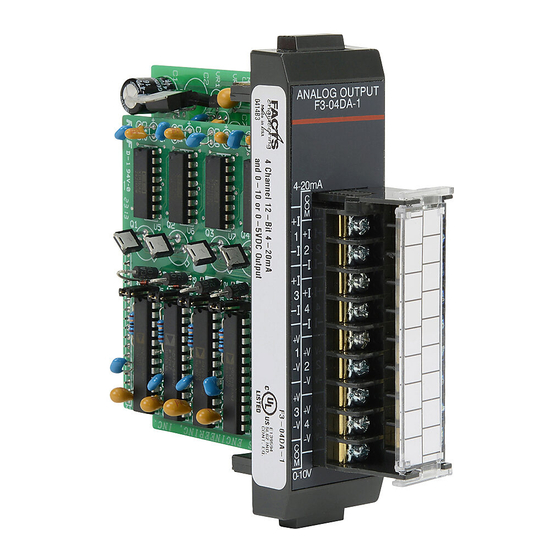
Chapter 7 : F3--04DA--1 4-Channel Analog Output
115
Connecting the Field Wiring
115
Wiring Guidelines
118
User Power Supply Requirements
118
Load Requirements
118
Removable Connector
119
Wiring Diagram
119
Module Specifications
115
Setting the Module Jumpers
115
Module Operation
120
Channel Scanning Sequence
120
Understanding the I/O Assignments
121
Channel Selection Inputs
121
Writing the Control Program
123
Identifying the Data Locations
123
Calculating the Digital Value
123
Sequencing the Channel Updates
127
Sequencing Example
127
Analog and Digital Value Conversions
128
Chapter 8 : F3--04DAS 4-Channel Isolated Analog Output
129
Module Specifications
129
Connecting the Field Wiring
129
Wiring Guidelines
135
User Power Supply Requirements
135
Load Requirements
135
Removable Connector
136
Wiring Diagram
136
Combining Voltage Outputs
136
Combining Current Outputs
137
Module Operation
138
Channel Scanning Sequence
138
Understanding the I/O Assignments
139
Channel Selection Inputs
139
Analog Data Bits
140
Writing the Control Program
141
Identifying the Data Locations
141
Calculating the Digital Value
141
Sequencing the Channel Updates
145
Analog and Digital Value Conversions
146
Chapter 9 : F3--08THM--N 8-Channel Thermocouple Input
147
Introduction
147
Module Specifications
147
Setting the Module Switches
147
Connecting the Field Wiring
147
Wiring Guidelines
151
User Power Supply Requirements
151
Wiring Diagram
151
Module Operation
152
Channel Scanning Sequence
152
Understanding the I/O Assignments
153
Active Channel Indicator Inputs
153
Temperature Sign Bit
154
Analog Data Bits
154
Temperature Input Resolution
154
Millivolt Input Resolution
154
Writing the Control Program
155
Identifying the Data Locations
155
Automatic Temperature Conversion
155
Using the Sign Bit
159
Temperature and Digital Value Conversions
164
Millivolt and Digital Value Conversions
164
Chapter 10 : F3--08TEMP 8-Channel Temperature Input
165
Module Specifications
165
Compatible Temperature Probe Specifications
167
Analog Input Configuration Requirements
167
Setting the Module Jumpers
168
Factory Settings
168
Selecting the Number of Channels
168
Connecting the Field Wiring
169
Wiring Guidelines
169
User Power Supply Requirements
169
Removable Connector
169
Wiring Diagram
169
Module Operation
170
Channel Scanning Sequence
170
Understanding the I/O Assignments
171
Active Channel Indicator Inputs
171
Analog Data Bits
172
Temperature Input Resolution
172
Writing the Control Program
173
Converting the Data to Temperature
174
Temperature and Digital Value Conversions
181
Appendix A: DL305 Data Types and Memory Map
182
DL330 Memory Map
182
DL330P Memory Map
182
DL340 Memory Map
182
I/O Point Bit Map
182
Control Relay Bit Map
182
Special Relays
182
Data Registers
182
DL350 System V-Memory
192
DL350 Comm Port 2 Control Relays
193
DL350 Memory Map
194
DL350 X Input/ y Output Bit Map
195
DL350 Control Relay Bit Map
196
DL350 Staget Control / Status Bit Map
198
DL350 Timer and Counter Status Bit Maps
200
Advertisement
Advertisement
Related Products
Automationdirect.com D4-470
Automationdirect.com DL05
Automationdirect.com DL06
Automationdirect.com DirectLOGIC DL205 Series
Automationdirect.com D4-454 PLC
Automationdirect.com P2-01AC
Automationdirect.com P2-01DCAC
Automationdirect.com P2-04AD
Automationdirect.com P2-04DA
Automationdirect.com P2-06RTD
Automationdirect.com Categories
I/O Systems
Control Unit
Controller
Temperature Controller
DC Drives
More Automationdirect.com Manuals
Login
Sign In
OR
Sign in with Facebook
Sign in with Google
Upload manual
Upload from disk
Upload from URL