
Subscribe to Our Youtube Channel
Related Manuals for Atlas Copco XAHS 37 DD


Summary of Contents for Atlas Copco XAHS 37 DD
- Page 1 XAHS 37 DD - XAHS 70 DD7 Engine Deutz XAS 47 DD - XAS 90 DD7 D2011L02 XAS 57 DD - XAS 110 DD7 Instruction Manual for Portable Compressors English...
- Page 3 Instruction Manual for Portable Compressors XAHS 37 DD - XAHS 70 DD7 XAS 47 DD - XAS 90 DD7 XAS 57 DD - XAS 110 DD7 Printed matter N° 2954 2140 02 ATLAS COPCO - PORTABLE AIR DIVISION www.atlascopco.com 07/2007...
- Page 4 While every effort has been made to ensure that the information in this manual is correct, Atlas Copco does not assume responsibility for possible errors. Copyright 2007, Atlas Copco Airpower n.v., Antwerp, Belgium. Any unauthorized use or copying of the contents or any part thereof is prohibited.
-
Page 5: Table Of Contents
Instruction Manual Follow the instructions in this booklet and we guarantee you years of troublefree operation. Please read the following instructions carefully before starting to use your machine. Always keep the manual available near the machine. In all correspondence always mention the compressor type and serial number, shown on the data plate. - Page 6 Instruction Manual ONTENTS ONTENTS 3 Operating instructions ............32 4.11 Storage ..............46 Parking, towing and lifting instructions....32 4.12 Service paks .............. 46 3.1.1 Parking instructions ..........32 4.13 Service kits..............46 3.1.2 Towing instructions ..........33 4.14 Compressor element overhaul ........46 3.1.3 Spillage-Free instruction...........
-
Page 7: Safety Precautions For Portable Compressors (With Generator)
To be read attentively and acted accordingly before towing, lifting, operating, performing maintenance or repairing the unit NTRODUCTION The policy of Atlas Copco is to provide the users of their equipment with The manufacturer does not accept any liability for any damage arising from safe, reliable and efficient products. -
Page 8: Safety During Transport And Installation
Instruction Manual 16 Take precautions against fire. Handle fuel, oil and anti-freeze with care 11 Locate the unit away from walls. Take all precautions to ensure that hot because they are inflammable substances. Do not smoke or approach air exhausted from the engine and driven machine cooling systems with naked flame when handling such substances. -
Page 9: Safety During Use And Operation
13 Never refill fuel while the unit is running, unless otherwise stated in the limits as indicated in the technical specifications. Atlas Copco Instruction Book (AIB). Keep fuel away from hot parts 27 Never operate the generator in excess of its limits as indicated in the such as air outlet pipes or the engine exhaust. -
Page 10: Safety During Maintenance And Repair
Submit the Parts shall only be replaced by genuine Atlas Copco replacement parts. generator to a testrun, check that the AC power performance is correct. All maintenance work, other than routine attention, shall only be undertaken when the unit is stopped. -
Page 11: Specific Safety Precautions
Instruction Manual PECIFIC SAFETY PRECAUTIONS Batteries When servicing batteries, always wear protecting clothing and glasses. The electrolyte in batteries is a sulphuric acid solution which is fatal if it hits your eyes, and which can cause burns if it contacts your skin. Therefore, be careful when handling batteries, e.g. -
Page 12: Leading Particulars
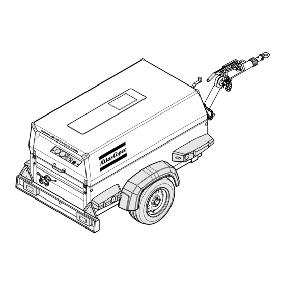
Fig. 2.1.b General view HardHat ENERAL DESCRIPTION The compressors type XAHS 37 DD - XAHS 70 DD7, XAS 47 DD - XAS 90 DD7 and XAS 57 DD - XAS 110 DD7 are silenced, single-stage, oil-injected screw compressors, built for a nominal effective working pressure, ranging from 7 bar up to 12 bar (see chapter 8, technical specifications). - Page 13 Instruction Manual – Regulation – Generator (option for XAS 47 DD - XAS 90 DD7) The compressor is provided with a continuous regulating system and The built-in generator is driven by a multi V-belt drive. The generated a blow-down valve which is integrated in the unloader assembly. The current can be drawn via 3 sockets (see chapter 8, Technical valve is closed during operation by outlet pressure of the compressor Specifications).
-
Page 14: Markings And Information Labels
Danger, heat flat. Service every 24 hours. Warning! Electrocution hazard. Part under pressure. Atlas Copco mineral compressor oil. Do not stand on outlet valves. Atlas Copco synthetic compressor oil. Start-Stop indication of switch. Atlas Copco mineral engine oil. Do not run the motor with open doors. -
Page 15: Main Parts
Instruction Manual ARTS Fig. 2.2 Main parts with some options Alternator Drain Plug Fuel Tank Hood Air Filter Engine Oil Level Dipstick Jockey wheel Anti-Frost Device (option) Engine Oil Filter (compressor element) Air outlet valves Exhaust Pipe Oil Filter (engine) Air Receiver Oil Level Gauge (compressor element) Brake Handle... - Page 16 Instruction Manual OMPRESSOR EGULATING YSTEM Without generator With generator Fig. 2.3 Air Filter Engine Oil Level Gauge Solenoid Valve Air Receiver Oil Separator (Speed regulator) Air Outlet Valves Flow Nozzle Pressure Gauge Temperature Switch Blow Down Valve Filler Plug Regulating Valve Unloader Assembly Compressor Element Flow Restrictor...
-
Page 17: Air Flow
Instruction Manual 2.3) IR FLOW When cold start equipment is installed; a thermostatic valve will bypass the compressor oil (oil will not pass through oil cooler The system comprises: ), until the working temperature is reached. Air filter AR/OS Air receiver/oil separator ONTINUOUS REGULATING SYSTEM Compressor element 2.3) -
Page 18: Electrical System
Instruction Manual LECTRICAL SYSTEM 2.8.1 C IRCUIT DIAGRAM STANDARD The compressor is equipped with a negative earthed system. 12V DC 14« 15« 13« 8« 5« 7« 6« D- D+ 1« Auxiliary 2« 12« 3« Temp General 4« alarm (Lamp- tester) 9´,10´,11´... - Page 19 Instruction Manual Engine is running normally: Oil pressure contact S3 opens, K3 no longer excited. K3 changes over (13-11), engine cuts out because fuel solenoid Y1 no longer excited and lamp H2 goes on simultaneously. Thermocontact S2 opens, K3 no longer excited. K3 changes over (13-11), engine cuts out because fuel solenoid Y1 no longer excited and lamp H2 goes on simultaneously.
-
Page 20: Control System)
Instruction Manual 2.8.2 C XAS 47 DDG - IRCUIT DIAGRAM The compressor is equipped with a negative earthed system. XAS 90 DD7G (G DDG 110V ENERATOR WITHOUT AUTOMATIC CONTROL SYSTEM (Not on HardHat) 12V DC Auxiliary To Circuit diagram 9822 1055 27 M1 M General Temp... - Page 21 Instruction Manual Operation of the electric circuit in detail Engine is running normally: Oil pressure contact S3 opens, K3 no longer excited. K3 changes over (13-11), engine cuts out because fuel solenoid Start switch S1 position 1: Y1 no longer excited and lamp H2 goes on simultaneously. Line 2 on 12V contact K3 closed (13-11), lamp H2 is on.
-
Page 22: Circuit Diagram Xas 47 Ddg - Xas 90 Dd7G (Generator Ddg 110V With Automatic Control System)
Instruction Manual 2.8.3 C XAS 47 DDG - IRCUIT DIAGRAM The compressor is equipped with a negative earthed system. XAS 90 DD7G (G DDG 110V ENERATOR WITH AUTOMATIC CONTROL SYSTEM (Not on HardHat) 12V DC Auxiliary To Circuit diagram 9822 1055 91 M1 M Temp General... - Page 23 Instruction Manual Operation of the electric circuit in detail Engine is running normally: Oil pressure contact S3 opens, K3 no longer excited. K3 changes over (13-11), engine cuts out because fuel solenoid Start switch S1 position 1: Y1 no longer excited and lamp H2 goes on simultaneously. Line 2 on 12V contact K3 closed (13-11), lamp H2 is on.
-
Page 24: Circuit Diagram Xas 47 Ddg - Xas 90 Dd7G (Generator Ddg It 230/400V Without Automatic Control System)
Instruction Manual 2.8.4 C XAS 47 DDG - IRCUIT DIAGRAM The compressor is equipped with a negative earthed system. XAS 90 DD7G (G DDG IT 230/ ENERATOR 400V WITHOUT AUTOMATIC CONTROL SYSTEM (Not on HardHat) 12V DC Auxiliary To Circuit diagram 9822 1055 25 M1 M General... - Page 25 Instruction Manual Operation of the electric circuit in detail Engine is running normally: Oil pressure contact S3 opens, K3 no longer excited. K3 changes over (13-11), engine cuts out because fuel solenoid Start switch S1 position 1: Y1 no longer excited and lamp H2 goes on simultaneously. Line 2 on 12V contact K3 closed (13-11), lamp H2 is on.
-
Page 26: Circuit Diagram Xas 47 Ddg - Xas 90 Dd7G (Generator Ddg It 230/400V With Automatic Control System)
Instruction Manual 2.8.5 C XAS 47 DDG - IRCUIT DIAGRAM The compressor is equipped with a negative earthed system. XAS 90 DD7G (G DDG IT 230/ ENERATOR 400V WITH AUTOMATIC CONTROL SYSTEM (Not on HardHat) 12V DC Auxiliary To Circuit diagram 9822 1055 90 M1 M General... - Page 27 Instruction Manual Operation of the electric circuit in detail Engine is running normally: Oil pressure contact S3 opens, K3 no longer excited. K3 changes over (13-11), engine cuts out because fuel solenoid Start switch S1 position 1: Y1 no longer excited and lamp H2 goes on simultaneously. Line 2 on 12V contact K3 closed (13-11), lamp H2 is on.
-
Page 28: Circuit Diagram Xas 47 Ddg - Xas 90 Dd7G (Generator Ddg It 230V, 6 Kva)
Instruction Manual 2.8.6 C XAS 47 DDG - IRCUIT DIAGRAM The compressor is equipped with a negative earthed system. XAS 90 DD7G (G DDG IT 230V, ENERATOR (Not on HardHat) 12V DC Auxiliary To Circuit diagram 9822 1055 26 M1 M Temp General alarm... - Page 29 Instruction Manual Operation of the electric circuit in detail Engine is running normally: Oil pressure contact S3 opens, K3 no longer excited. K3 changes over (13-11), engine cuts out because fuel solenoid Start switch S1 position 1: Y1 no longer excited and lamp H2 goes on simultaneously. Line 2 on 12V contact K3 closed (13-11), lamp H2 is on.
-
Page 30: Circuit Diagram Cold Start (All Types)
Instruction Manual 2.8.7 C IRCUIT DIAGRAM COLD START ALL TYPES 12V DC Auxiliary Temp General alarm (Lamptester) Fig. 2.11 Circuit diagram (No. 9822 0864 00) Circuit breaker (10 A) Contact switch (Off-On-Override-start) Alternator Temperature switch engine Battery Oil pressure switch engine Temperature alarm lamp Temperature lamptest switch General alarm lamp... -
Page 31: Circuit Diagram Refinary Equipment (All Types)
Instruction Manual 2.8.8 C IRCUIT DIAGRAM REFINARY EQUIPMENT ALL TYPES 12V DC See Note 1 Temp General alarm (Lamptester) See Note 1 Fig. 2.12 Circuit diagram (No. 9822 0909 00) Circuit breaker (10 A) Contact switch (Off-On-Override-start) Alternator Temperature switch engine Battery Oil pressure switch engine Temperature alarm lamp... -
Page 32: Operating Instructions
Instruction Manual OPERATING INSTRUCTIONS ARKING TOWING AND LIFTING INSTRUCTIONS When parking a compressor, secure support leg (1) or jockey wheel (2) to support the compressor in a level position. Be sure that the jockey wheel (2) is blocked by the blocking pin (6). Safety precautions. -
Page 33: Towing Instructions
Instruction Manual 3.1.2 T 3.1.4 H OWING INSTRUCTIONS EIGHT ADJUSTMENT WITH ADJUSTABLE TOWBAR Before towing the compressor, ensure that the towing Before towing the compressor, make sure that the joints equipment of the vehicle matches the towing eye or ball of the towbar are secured with maximum strength connector, and ensure that the hood is closed and locked without damaging the towbar. -
Page 34: Lifting Instructions
Instruction Manual 3.1.5 L IFTING INSTRUCTIONS TARTING TOPPING 3.2.1 B EFORE STARTING 1. Before initial start-up, prepare battery for operation if not already done. See section 4.9. 2. With the compressor standing level, check the level of the engine oil. Add oil, if necessary, to the upper mark on dipstick. Consult the Engine Operation Manual for the type and viscosity grade of the engine oil. -
Page 35: Starting Procedure (With Cold Start; Option)
Instruction Manual 3.2.2 S TARTING PROCEDURE WITH COLD START OPTION Hourmeter Circuit breaker button Working pressure gauge Temperature alarm lamp (red) General alarm lamp (red) Start switch Lamp test button Cold start button Fig. 3.12 Control panel (with cold start; option) The control panel indicates receiver pressure (PG) and accumulated operating hours (P1). -
Page 36: Starting Procedure (Without Cold Start)
Instruction Manual 3.2.3 S TARTING PROCEDURE WITHOUT COLD START Hourmeter Circuit breaker button Working pressure gauge Temperature alarm lamp (red) General alarm lamp (red) Start switch Lamp test button Fig. 3.15 Control panel (without cold start) The control panel indicates receiver pressure (PG) and accumulated operating hours (P1). -
Page 37: During Operation
Instruction Manual 3.2.4 D 3.2.6 F URING OPERATION AULT SITUATIONS AND PROTECTIVE DEVICES When the engine is running, the air outlet valves (ball – A fault which occurs with the engine, either: oil pressure (too valves) must always be put in a fully opened or fully low), oil temperature (too high) or alternator voltage (too low) closed position. -
Page 38: Function Of Generator (Option)
Instruction Manual UNCTION OF GENERATOR OPTION Start the unit in accordance with the normal procedure (see section 3.2). Let the motor warm up until it reaches operational temperature. 3.3.1 F DDG 110V UNCTION OF GENERATOR Turn the green switch S7 to position 1. WITHOUT AUTOMATIC CONTROL SYSTEM The normal control system is switched off and the motor speed increases to reach the maximum. -
Page 39: Automatic Control System (Option)
Instruction Manual 3.3.2 F DDG 110V Operation with automatic control switch S8 “OFF” UNCTION OF GENERATOR WITH AUTOMATIC CONTROL SYSTEM OPTION – Switch generator main switch S7 “ON”. UNCTIONAL DESCRIPTION – Generator is disconnected from socket. – Engine reaches nominal speed. –... - Page 40 Instruction Manual 3.3.3 F DDG 230/400V UNCTION OF GENERATOR 230V - 3 PH WITHOUT AUTOMATIC CONTROL SYSTEM UNCTIONAL DESCRIPTION X1.1 X1.2 X1.3 H3/S7 Fig. 3.27 Generator control box Fig. 3.26 Control panel (generator) Generator DDG 230/400V: Generator DDG 230/400V: Main circuit breaker 4-pole + shunt trip coil Switch Insulation monitoring relay Lamp (green)
-
Page 41: Function Of Generator Ddg 230/400V And 230V - 3Ph With Automatic Control System (Option) - Functional Description
Instruction Manual 3.3.4 F DDG 230/400V Operation with automatic control switch S8 “ON” UNCTION OF GENERATOR 230V - 3 PH WITH AUTOMATIC CONTROL – Switch generator main switch S7 “ON”. ) - F SYSTEM OPTION UNCTIONAL DESCRIPTION – Generator is disconnected from socket. –... -
Page 42: Maintenance
O-rings, washers. low. For engine maintenance refer to Engine Operation Manual. Order Service Paks at your local Atlas Copco dealer. The maintenance schedule has to be seen as a guideline for units operating in a dusty environment typical to compressor applications. -
Page 43: Lubrication Oils
1615 5954 00 - 210 liter barrel: order number 1615 5955 00 PAROIL from Atlas Copco is the ONLY oil tested and approved for use in all engines built into Atlas Copco compressors and generators. Synthetic engine oil PAROIL 5W40:... -
Page 44: Check Compressor Oil Level
When operating in high ambient temperatures, in very dusty or high humidity conditions, it is recommended to change the oil more frequently. In this case, contact Atlas Copco. 1. Run the compressor until warm. Close the outlet valve(s) (5) and stop the compressor. Wait until the pressure is released through the automatic blow-down valve. -
Page 45: Cleaning Coolers
Instruction Manual LEANING COOLERS LEANING FUEL TANK Observe all relevant environmental and safety precautions. Place an appropriate drain pan under the drainplug (Fig. 2.2, DP of the fuel tank. Remove the drain plug. Lift the towbar (Fig. 2.2, TB) and tilt the compressor approx. 15° to remove all fuel, dirt and water. -
Page 46: Activating A Dry-Charged Battery
When The order number of the Service Paks are listed in the Atlas Copco charging batteries, each cell must be open, i.e. plugs and/or cover Parts List (ASL). -
Page 47: Adjustments And Servicing Procedures
6. Close the outlet valves (AOV), check that the pressure is between bar(e) bar(e) bar(e) bar(e) Z1 and Z2 bar(e) (see table). Lock the regulating valve (RV) by XAHS 37 DD - pushing the knob down. XAHS 70 DD7 13.5 13.3 – 13.7 7. -
Page 48: Air Filter Engine/Compressor
5.2.2 R ECOMMENDATIONS IR RECEIVER The Atlas Copco air filters are specially designed for the application. The use of non-genuine air filters may The air receiver is tested according to official standards. Regularly lead to severe damage of engine and/or compressor have inspections carried out in conformity with local regulations. -
Page 49: Fuel System
Instruction Manual UEL SYSTEM 5.6.1 B RAKE SHOE ADJUSTMENT Check the thickness of the brake lining. Remove both black plastic plugs (5), one on each wheel. When the brake lining has been worn to a thickness of 2 mm or less, the brake shoes have to be replaced. After inspection and/or replacement re-insert both plugs. -
Page 50: Test Procedure Of Brake Cable Adjustment
(Section 5.6.3) RIVE Never retense or reuse the drive belt between engine and compressor. Consult Atlas Copco for replacement of drive belt. D. Too tight; adjust brake cables (Section 5.6.3) Fig. 5.6 Correct and wrong position of markings... -
Page 51: Problem Solving
If it’s not possible to solve the problem with this 4. Never operate the engine without the main or voltage sensing problem solving table, please consult Atlas Copco. cables connected in the circuit. Problem... - Page 52 Check the maximum speed, service the fuel filter. e. Oil separator element (OS) clogged. e. Have element removed and inspected by an Atlas Copco Service representative. 12. Working pressure rises during a. See faults 10. a. See remedies 10.
-
Page 53: Available Options
Not in combination with HardHat. Not on XAHS 37 DD - XAHS 70 DD7. In order to obtain a spare key at the local ABUS dealer, the key code card must be presented. Please keep this card available. -
Page 54: Technical Specifications
(M32) +/- 25 Note: Secure the tank cap and drain plug of the fuel tank handtight. ETTINGS OF SHUTDOWN SWITCHES AND SAFETY VALVES XAHS 37 DD - XAS 47 DD - XAS 57 DD - Compressor type XAHS 70 DD7... -
Page 55: Compressor/Engine Specifications
Instruction Manual OMPRESSOR NGINE SPECIFICATIONS XAHS 37 DD - XAS 47 DD - XAS 57 DD - Compressor type XAHS 70 DD7 XAS 90 DD7 XAS 110 DD7 Designation Unit Value Value Value Reference conditions 1. Absolute inlet pressure bar(e) 2. - Page 56 Instruction Manual XAHS 37 DD - XAHS 70 DD7 LTITUDE UNIT PERFORMANCE CURVES Max. allowable working pressure as a function altitude and ambient temperature. TEMPERATURE °F 5000 16 405 8.0 bar(e) 116 psi 4000 13 124 9.0 bar(e) 131 psi 10.0 bar(e)
- Page 57 Instruction Manual XAS 47 DDG - XAS 90 DD7G LTITUDE UNIT PERFORMANCE CURVES Max. allowable working pressure as a function altitude and ambient temperature. TEMPERATURE °F 5000 16 405 4000 13 124 4.0 bar(e) 58 psi 3000 9 843 5.0 bar(e) 73 psi 6.0 bar(e) 87 psi...
- Page 58 Instruction Manual XAHS 37 DD - XAS 47 DD - XAS 47 DDG - XAS 57 DD - Compressor type XAHS 70 DD7 XAS 90 DD7 XAS 90 DD7G XAS 110 DD7 DDG IT Designation Unit Value Value Value Value Performance data 1.
- Page 59 Instruction Manual XAHS 37 DD - XAS 47 DD - XAS 47 DDG - XAS 57 DD - Compressor type XAHS 70 DD7 XAS 90 DD7 XAS 90 DD7G XAS 110 DD7 DDG IT Designation Unit Value Value Value Value...
- Page 60 Instruction Manual Generator type DDG 110V DDG IT 230V - DDG IT 230/400V - 3 ph - 6kVA 3 ph - 6kVA (XAS 47 DDG - (XAS 47 DDG - (XAS 47 DDG - XAS 90 DD7G / DDG IT) XAS 90 DD7G / DDG IT) XAS 90 DD7G / DDG IT) Designation...
-
Page 61: Conversion List Of Si Units Into British Units
Instruction Manual Unit dimensions without brakes towbar fixed adjustable Length 2,980 3,257/3,495 Width 1,330 1,330 Height 1,252 1,252 Weight (ready to operate) with brakes towbar fixed adjustable Length 3,093 3,460/3,628 Width 1,330 1,330 Height 1,252 1,252 Weight (ready to operate) ONVERSION LIST OF UNITS INTO RITISH... -
Page 62: Data Plate
Instruction Manual DATA PLATE 1. Company code 2. Product code 3. Unit serial number 4. Name of manufacturer 5. EEC or national type approval number 6. Vehicle identification number 7. A Maximum permitted total weight of the vehicle B Maximum permitted axle load C Maximum permitted load on the towing eye 8. - Page 64 www.atlascopco.com...
Need help?
Do you have a question about the XAHS 37 DD and is the answer not in the manual?
Questions and answers
My engine want stay running after I release starter button. The oil light is not on during the start up so when I release the starter button it cuts off. Engine oil level is good and put it new oil sending unit.
The Atlas Copco XAHS 37 DD engine could shut off after releasing the starter button due to the following possible causes:
1. The start switch (S1) was released too soon before engine oil pressure built up above the minimum allowed value.
2. There is insufficient engine oil pressure.
3. The fuel tank contains insufficient fuel.
This answer is automatically generated