TuffStuff apollo standard Assembly Instructions Manual
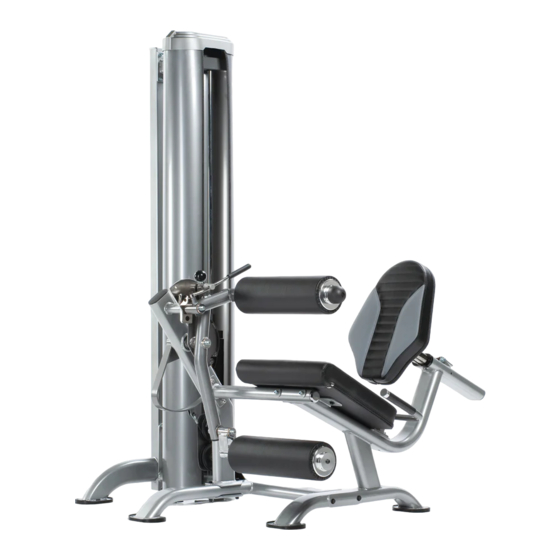
Modular gym system inner outer thigh station
Hide thumbs
Also See for apollo standard:
- Assembly instructions manual (8 pages) ,
- Assembly instructions manual (8 pages) ,
- Assembly instructions manual (12 pages)

Related Manuals for TuffStuff apollo standard


Summary of Contents for TuffStuff apollo standard
- Page 1 A S S E M B L Y I N S T R U C T I O N S Revision Date 08-23-05 Apollo Modular Gym System Inner Outer Thigh Station Standard Deluxe A m e r i c a ’ s P r e m i e r E x e r c i s e E q u i p m e n t Inner Outer Thigh Station Rev0...
-
Page 2: Main Frame Assembly
Stuff Equipment 2. Neatly organize and identify all parts according to the Parts List This Tuffstuff product has been built to precise quality standards and the Exploded View Diagram. and has been carefully packaged to ensure that damage will not occur during shipment. - Page 3 Weight Stack Frame Weight Stack Frame Note: Some parts have been cut away for clarity. Inner Outer Thigh Station...
- Page 4 Step 2 Attach Pivot Legs to Main Frame Attach a Pulley 3/8 X 3 1/2 (#22) and a Small Cover Plate 3 1/2 Pulley (#19) to the Cam Support Tube (#5) using hardware shown. Insert the Pivot Axles (#14) into the receptacles of the Main Frame (#11). Next, attach the Cam Support Tube (#5) and the Adjustable Cam Plate (#2) to the right side Pivot Axle (#14).
- Page 5 Step 3 Connect Pivot Legs Maneuver the two Pivot Axles (#14) into the holes on the bottom side of the Pivot Axle Support Tube (#15). Next, loosely fasten the Pivot Axle Support Tube (#15) along with the two captive Pivot Axles (#14) to the Main Frame (#11) using hardware shown.
- Page 6 Step 4 Handles and Leg Pad Pivot Brackets Assembly Attach the Handles (#6, #7) to the Main Frame (#11) using hardware shown. Insert the Leg Pad Pivot Brackets (#10) into the receptacles of the Pivot Legs (#8, 16). Next, secure the Leg Pad Brackets (#10) using the two Retaining Snap Rings (#49).
- Page 7 Note: Some parts have been cut away for clarity. Inner Outer Thigh Station...
- Page 8 Step 5 Seat Pad and Back Pad Assembly Attach the Seat Pad (#17) to the Main Frame (#11) using hardware shown. Attach the Back Pad (#4) to the Adjustable Back Pad Tube (#1) using hardware shown. Next, insert the Adjustable Back Pad Tube (#1) into the receptacle of the Main Frame (#11).
- Page 9 Note: Some parts have been cut away for clarity. Inner Outer Thigh Station...
-
Page 10: Cable Routing
Step 6 Cable Routing A. Connect the Weight Stack Cable (#20) to the Top Plate Selector Bar using hardware shown. See FIG. A. B. Next, route the Weight Stack Cable (#20) up and over the Pulley 3/8 X 4 1/2 (#23-Labeled ), then route down and under the Pulley 3/8 X 4 1/2 (#23-Labeled C. - Page 11 CHART Inner Outer Thigh Station (Deluxe) BOLD FONT = SUB-ASSEMBLY PARTS REGULAR FONT = HARDWARE Parts List ITEM NO. DESCRIPTION PART NO. QTY. ITEM NO. DESCRIPTION PART NO. QTY. ADJUSTABLE BACK PAD TUBE UP0361 HEX HEAD CAP SCREW GR-5 B/O 3/8-16 X 3 1/4 BNH0312 ADJUSTABLE CAM PLATE UP0846...
- Page 12 (3) months, and all other parts not mentioned elsewhere in this warranty will expire one (1) year from the date of delivery to the original purchaser. The obligation of TuffStuff under this warranty is limited to repairing or re- placing warranted defective parts, as TuffStuff may elect, at TuffStuff’s facility in Pomona, California, without charge to purchaser for either parts or labor.
Need help?
Do you have a question about the apollo standard and is the answer not in the manual?
Questions and answers