Advertisement
O W N E R ' S
TABLE OF CONTENTS:
Introduction - Pg. 1
Safety Precautions - Pg. 2
Assembly for CFM-550
Pg. 3 - Pg. 17
Cable Adjustments Diagram- Pg. 18
Cable Mapping Diagram - Pg. 20
Exploded View Diagram - Pg. 21
Parts List - Pg. 22
Pg. 23 - Pg. 24
Maintenance - Pg. 25
Warranty - Back Page
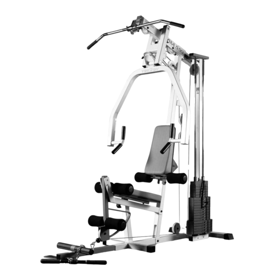
CFM-550
Compact Frontal Machine
© 2000 TASK INDUSTRIES, INC.
A m e r i c a ' s
P r e m i u m
M A N U A L
48"
L 75" W 48" H 84"
E x e r c i s e
E q u i p m e n t
Revision Date 06-26-01
75"
CFM-550 Rev. 0
Advertisement
Table of Contents

Related Manuals for TuffStuff CFM-550


Summary of Contents for TuffStuff CFM-550
-
Page 1: Table Of Contents
M A N U A L TABLE OF CONTENTS: Introduction - Pg. 1 Safety Precautions - Pg. 2 Assembly for CFM-550 Pg. 3 - Pg. 17 Cable Adjustments Diagram- Pg. 18 Cable Mapping Diagram - Pg. 20 Exploded View Diagram - Pg. 21 Parts List - Pg. -
Page 2: Introduction
CFM-550 in the area where it is to be used upon completion. 3. It is recommended that another person assist you with the assembly of this unit. -
Page 3: Safety Precautions
Fig. 3 Caution: Check the Turn/Pull Pin w/Knob (#39) to be fully X 3-1/2 (#38) and the Turn/Pull Pin w/Knob (#39) on this unit. engaged into the selected hole of the Bench Press Adj. Seat Tube (#9). CFM-550 Compact Frontal Machine... - Page 4 (#1), as Note: When positioning the Base Frame (#1) consider the shown above. complete area surface of the CFM-550. Use the overhead view on the cover page for designing your layout before assembling. FIG. 6 Next, locate the Rear Upright (#2) and, using a rubber mallet, FIG.
- Page 5 2-3/4 (#14) with multi-purpose grease prior to assembling. assembly process. LOOSELY FASTEN Next, using a rubber mallet, insert one Plastic Insert Cap 2” Sq. (#53) into the front of the Leg Extension Bench Frame (#4). CFM-550 Compact Frontal Machine...
- Page 6 Set Screws 1/4-20 X 3/8 (#42), as (#53) into the tube-ends of the Press Bar Selector Housing (#7), as shown above. Use the supplied Hex Key 1/8” (#86) for fastening these shown above. Set Screws. CFM-550 Compact Frontal Machine...
- Page 7 Be sure that the weight is distributed over your knees or legs when lifting. Also, it is advisable to wear a well fitted lifting belt during heavy lifting. CFM-550 Compact Frontal Machine...
- Page 8 Plastic Insert Caps 1 X 2 ( #51) into the tube- cated on the bottom side of the Guide Rod Retainer Housing (#11), as ends, as shown above. shown above. CFM-550 Compact Frontal Machine...
- Page 9 Press Arm (#6) until it becomes flush with both sides of the Press Bar Selector Housing (#7). Note: It is recommended to grease the Pivot Axle 1 X 8-1/8 (#15) with multi-purpose grease prior to assembling. CFM-550 Compact Frontal Machine...
- Page 10 Pivot Axles (#15). Hex Head Cap Screw 3/8-16 X 2-3/4 (#75), two Flat Washers SAE 3/8” (#60), and one Nylon Insert Jam Lock Nut 3/8-16 (#68). CFM-550 Compact Frontal Machine...
- Page 11 Nylon Pulley 4 1/2 Rd. (#45-Labeled A) and into the tube of the Top Pulley Housing (#3), as Note: Refer to Fig. 66 on page 19 for further clarification of this shown above. assembly. CFM-550 Compact Frontal Machine...
- Page 12 Front Upright (#5) and secure it into place using one Hex Head Cap Screw 3/8-16 X 2-1/2 (#74), two Flat Washers SAE 3/8” (#60), and one Nylon Insert Jam Lock Nut 3/8-16 (#68). CFM-550 Compact Frontal Machine...
- Page 13 Pulley Bracket (#16) and under the Nylon Pulley 4 1/2 Rd. (#45- Labeled G), as shown above. Note: Use Cable Mapping Diagram on page 20 for further detailed illustration of the Lat Cable (#27) routing. CFM-550 Compact Frontal Machine...
- Page 14 Cap Screw 1/4-20 X 1-1/2 (#63), and one Nylon Insert Lock Nut 1/4-20 Note: Use Cable Mapping Diagram on page 20 for further detailed (#64). illustration of the Leg Extension Cable (#28) routing. Note: Refer to Fig. C on page 20 for further illustration of this assembly. CFM-550 Compact Frontal Machine...
- Page 15 Frame (#9), as shown above, using two Hex Head Cap Screws 3/8-16 X bled Bench Press Adj. Seat Frame (#9) into the Leg Extension Bench 1-3/4 (#73), and two Flat Washers SAE 3/8” (#60). Frame (#4). CFM-550 Compact Frontal Machine...
- Page 16 In addition, a measuring tape is used to center the Foot Roll Tube 1 X 23-3/4 (#19). The measurement from one end of the tube to the receptacle, as pictured above, should be about 10-1/2”. CFM-550 Compact Frontal Machine...
- Page 17 1/2” combination wrench to fasten this assembly properly. Note: To facilitate the insertion of these Rubber Grips, use Windex or household glass cleaner. Note: Refer to Fig. A on page 20 for further illustration of this assembly. CFM-550 Compact Frontal Machine...
- Page 18 (#23, #24, #25) in the corresponding order. Begin with the 15 at the top, Low Row Bar (#29) to the Lat Cable (#27) with out loosing traveling 20 next, and so on. range on the Weight Stack. CFM-550 Compact Frontal Machine...
-
Page 19: Cable Adjustments Diagram
CFM-550 CABLE ADJUSTMENTS DIAGRAM Cable Adjustment for: Adjustable Pulley Bracket (#17) 1. Loosen the bottom Regular Hex Nut (#70). 2. Adjust the top Nylon Insert Jam Lock Nut (#58) to give the cable proper tension. 3. Re-tighten the bottom Regular Hex Nut (#70) to complete the cable adjustment. - Page 20 FIG. 64 FIG. 65 FIG. 67 FIG. 66 FIG. 69 FIG. 68 CFM-550 Compact Frontal Machine...
-
Page 21: Cable Mapping Diagram
CFM-550 Compact Frontal Machine... -
Page 22: Exploded View Diagram
CFM-550 Compact Frontal Machine... -
Page 23: Cfm-550 Parts List
PLASTIC END CAP W/ GROOVE 2" SQ. BNH0136 DECAL-TUFF STUFF SIZE 1-3/8 X 8-7/16 BNH0139 PLASTIC END CAP W/GROOVE 2 X 3 BNH0049 DECAL CFM-550 BNH1058 PLASTIC INSERT CAP 1-1/4 RD. BNH0573 EXERCISE WALL CHART BNH0745 CFM-550 Compact Frontal Machine... -
Page 24: Adjustment Features
3. Adjust the Press Bar (#6) to the desired position. 4. Release the Push Pull Pin 1/2” X 3-1/2 (#38) and make sure it fully engages into the selected hole of the Press Bar’s (#6) Plate. CFM-550 Compact Frontal Machine... - Page 25 Weight Plate. Leg Curl Locked Leg Extension Arm used on Exercises: ♦ Low Row ♦ Standing Arm Curl ♦ Inner / Outer Thigh ♦ Seated Row ♦ Seated Chest Press ♦ Seated Shoulder Press CFM-550 Compact Frontal Machine...
-
Page 26: Maintenance
(See Fig. 76). In addition, be sure the springs in the Push Pull Pins 1/2 X 3-1/2 (#38) operating freely. 9. Check welds to be free of cracks. 10. Failure to perform routine maintenance could result in personal injury and/or equipment damage. CFM-550 Compact Frontal Machine... - Page 27 N o t e s CFM-550 Compact Frontal Machine...
-
Page 28: Warranty
TuffStuff. Limitations: The foregoing shall constitute the sole remedy of the purchaser and the sole liability of TuffStuff with regard to warranty, whether express or implied by operation of law or otherwise, including but not limited to any implied warranties of merchantability or fitness.
Need help?
Do you have a question about the CFM-550 and is the answer not in the manual?
Questions and answers
Cable is slack,need help with location etc.
Are there differences in the CFM 500 and the CFM 555? I have an unassembled CFM 555. Are there specific assembly instructions for it?