Table of Contents
Advertisement
Conforms to ANSI STD Z21.58b-2012
OUTDOOR COOKING GAS APPLIANCE
Tools needed for assembly:
Phillips screwdriver, Pliers or Adjust-
able Wrench
DANGER
If you smell gas:
1. Shut off gas to the appliance.
2. Extinguish any open flames.
3. Open lid.
4. If odor continues, keep away from the
appliance and immediately call your
fire department.
Failure to follow these instructions could
result in fire or explosion which could
cause property damage, personal injury
or death.
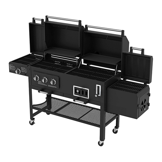
Grill & Smoker
PS9900
DANGER
1. Never operate this appliance unat-
tended.
2. Never operate this appliance within
10 ft (3.0 m) of any structure, com-
bustible material or other gas cylin-
der.
3. Never operate this appliance within
25 ft (7.5 m) of any flammable liquid.
4. Do not fill cooking vessel beyond
maximum fill-line.
5. Never allow oil or grease to get hot-
ter than 400°F or 200°C. If the tem-
perature exceeds 400°F (200°C) or
if oil begins to smoke, immediately
turn the burner or gas supply OFF.
6. Heated liquids remain at scalding
temperatures long after the cooking
process. Never touch cooking appli-
ance until liquids have cooled to
115°F (45°C) or less.
7. If a fire should occur, keep away
from the appliance and immediately
call your fire department. Do not at-
tempt to extinguish an oil or grease
fire with water.
Failure to follow these instructions could
result in fire or explosion which could
cause property damage, personal injury
or death.
Advertisement
Table of Contents

Related Manuals for Smoke hollow PS9900


Summary of Contents for Smoke hollow PS9900
- Page 1 Grill & Smoker PS9900 Conforms to ANSI STD Z21.58b-2012 OUTDOOR COOKING GAS APPLIANCE DANGER 1. Never operate this appliance unat- tended. 2. Never operate this appliance within 10 ft (3.0 m) of any structure, com- bustible material or other gas cylin- der.
- Page 2 WARNING DANGER For Outdoor Use Only Never use the gas or charcoal grill ● (outside of any type of enclosure) for INDOOR cooking or heating Never use the grill on or in a boat or ● recreational vehicle The combustion fumes from either the gas or charcoal grill are toxic and can cause severe illness and possibly death.
- Page 3 Read all safeguards and assembly instruc- In order to properly assemble your tions before assembling and operating smoker, you will only need two tools: your grill/smoker. Phillips head screwdriver ● Pliers or adjustable wrench ● Before assembling your new grill/smoker, (tools not included) unpack all the parts from the box.
- Page 4 SAFETY WARNINGS 1. The installation of this grill must conform to local codes, or in the absence of local codes, with either the National Fuel Gas Code, ANSI Z223.1 / NFPA 54, Natural Gas and Propane Installation Code, CSA B149.1, or Propane Storage and Handling Code, B 149.2, or The Standard for recreational Vehicles, ANSI 119.2 / NFPA, and CSA Z240 RV Series, Recreational Vehicle Code, as Acceptable.
-
Page 5: Save These Instructions
READ ALL SAFEGUARDS AND INSTRUCTIONS THOROUGHLY! YOUR SAFETY IS VERY IMPORTANT – FAILURE TO FOLLOW PROPER PROCEDURES AND SAFEGUARDS MAY RESULT IN PROPERTY DAMAGE, PERSONAL INJURY OR DEATH. DANGER DANGER Do not move the unit while it is being used. The GRILL is for outdoor use only! ●... - Page 6 PS9900 Parts List Note: For assistance, including missing or damaged parts, call toll free - 866-475-5180 from 8:30 am - 4:30 pm Central Time, Monday - Friday Hardware Pack Item Quantity Description M6X15 Combo Head Bolts M6X30 Combo Head Bolts ST4.0*10 Combo Head Screws...
- Page 7 PS9900 Parts List Item NO. Quantity Description Part No. Gas And Charcoal Cabinet With Lids PS9900-01 Burner Tubes With Ignition Electrodes 47183T-02 HVR Cover 47183T-03 Control Panel Assembly 47183T-04 Sear Burner Housing and Lid Assembly PS9500-05 Firebox Housing. 47183T-06 Locking Caster Wheels...
- Page 8 Assembly Note: Carefully cut the straps holding the carton together. Cut the carton sleeve so that it can lay flat on the ground to provide a clean surface for assembling your Grill. Remove the packing materials and all the parts from inside the Cabinet. After unpacking all the parts, check to make sure you HAVE all the parts.
- Page 9 Assembly Step 2: Rear Leg Assembly Step 2 Locate: Left Rear Leg #3 and Right Right Rear Leg #1 Rear Leg #1 and (6) M6x15 bolts Left Rear Leg #3 Procedure: Attach Left Rear Leg us- ing (2) M6x15 bolts and Right Rear Leg using (4) M6x15 bolts, as shown in Fig.
- Page 10 Assembly Step 3: Assembly of the Cart Left Side Fig. 3 Step 3 Panel: Locate: Locate the Cart Left Side Panel and (4) M6x15 Bolts and the Assembled Grill Procedure: Refer to Fig. 3 and slide the Panel into position on the Left Side of the Grill, inside the Legs.
- Page 11 Assembly Step 4: Assemble the Side Drip Tray Guides Step 4 Fig. 4A Locate: (2) Side Drip Tray Guides, (1) Center Drip Tray Guide and (10) M6x15 bolts. Procedure: Place a side Drip Tray Guide inside the Left Side Legs, as shown in Fig. 4A and fas- ten with (4) M6x15 bolts.
- Page 12 Assembly Step 5: Caster Wheels Assembly Step 5 Locate: Bottom Shelf and (4) Locking Caster Wheels Procedure: Refer to Fig. 5, and screw a Caster Wheel into each of the (4) corners of the bottom of the Bottom Shelf. Then, using the wrench, tighten the nut holding the Caster wheel securely.
- Page 13 Assembly Step 7: Locking the Caster Wheels Step 7 Locked Locate: The Assembly you have just pre- pared Procedure: Refer to Fig. 7. Each Caster Wheel has a tab on its side. Push down on each tab and check that the wheel can- not turn.
- Page 14 Assembly Step 9: Attach the Cart Front Panel Fig. 9 Step 9 Locate: Cart Front Panel, Assembled: Cart Left Side Panel, Front Vertical Support and Bottom Shelf and (6) M6x15 bolts Procedure: Refer to Fig. 9. Attach the Cart Front Panel to the (2) threaded holes in the Bottom Shelf with (2)M6x15bolts.
- Page 15 Assembly Step 11: Turn the Grill to be Upright. Step11 Fig.11 Locked Now, with the help of at least one other person, turn the Grill Assembly right side up. It should look like the Fig. 11. Step 12 Fig.12 Step 12: Assemble the Firebox Support Brace Locate: Firebox Support Brace, (4) M6x15 Bolts and (4) M6 KEPS nuts.
- Page 16 Assembly Step 13. Attach the Condiment Racks Step 13 Fig.13A Locate: Middle Condiment Rack, Lower Condiment Front Mesh and (6) M6x15 bolts. Procedure: Attach Middle Condiment Rack to the Left Front Leg, Front Vertical Support and the Cart Front Panel with (4) M6x15 bolts.
- Page 17 Assembly Step 15: Assemble Handle to the Gas Lid Step 15 Fig.15 Locate: Gas Lid, (2) Handle Stand-offs, (1) Long Handle Tube, (4) M6x15 bolts and (1) Gas Lid Heat Shield Gas Lid Heat Shield Procedure: Refer to Fig. 15. Open the Gas Grill Lid and fit the Heat Shield in place in- side the lid over the (4) holes for attaching the Handle.
- Page 18 Assembly Step 17: Attach the Smoke Stack Step 17 Locate: Charcoal Lid Assembly, (1) Fig.17 A Smoke Stack Assembly, (4) M6x15 bolts and (4) M6 KEPS nuts, and (2) Heat Indi- cators Procedure: Refer to Fig. 17A and unscrew Fig.17 B Fig.17 C the dome nut, and remove it and the small spring which attaches the Cap to the...
- Page 19 Assembly Step 18: Installing the Charcoal Tray Step 18 Lifting System Fig. 18 A Locate: Charcoal Tray Lift System Lift Han- dle, (2) Hinge Pins and (2) “R” Clips Procedure: Refer to Figs. 18A and 18B and Slide the Lift Handle through the adjusting slot and through the hole of the inside plate.
- Page 20 Assembly Step 19: Attach the Handle to the Firebox Step 19 Lid and the Firebox to the Grill Assembly Fig.19 A Locate: Firebox and Lid Assembly, (2) Han- dle Stand-offs, (1) Short Handle Tube, (10) M6x15 bolts, and (6) KEPS nuts Procedure: Refer to Fig.
- Page 21 Assembly Step 21: Installing the Control Panel As- Step 21 sembly Fig. 21 Igniter Wire 2 Locate: Fig. 21A shows the inside of the Igniter Wire 3 Control Panel Assembly ( CP has (3) gas Igniter Wire 1 valves mounted on a manifold connected to the Hose, Sear Burner Valve and Regu- lator assembly (HVR).
- Page 22 Assembly Step 22: Attaching the HVR Cover Step 22 Rivnut Fig.22 Locate: HVR Cover and (2) M6x15 bolts Procedure: Refer to Fig. 22 and set the HVR Cover in the front corner of the Gas Grill Cabinet, so that it covers the actual HVR where it enters and exits the Cabinet.
- Page 23 Assembly Step 24:Sear Burner Assembly Step 24 Fig. 24 A Locate: Sear Burner Housing and Lid, Sear Burner, Gas Valve Control Knob, (11) M6x15 bolts and (2) ST4.0x10 screws, (2) Handle Fig. 24 B Stand-offs, (1) short Handle Tube. Procedure: Refer to Fig.24A - Open the Sear Burner Lid and place (2) M6x15 bolts through the Lid holes on one side of the Lid.
- Page 24 Assembly Step24:SearBurner Assembly (Continued) Step 24 Continued. Fig. 24 F Refer to Fig. 24F – Place the Sear Burner Gas Control Knob over the valve stem, mak- ing certain to align the flat portion of the stem with the flat potion in the Knob and push the Control Knob onto the stem until it is firmly seated.
- Page 25 Assembly Step 25: Installing the Igniter Battery Step 25 Locate: The AA battery can be found on the Hardware Blister Card Fig. 25 Procedure: Refer to Fig. 25 – unscrew the black cap from the Electronic Igniter. In- sert the AA battery with the + end facing out.
- Page 26 Assembly Step 27 Fig. 27 A Step 27: Attach handles to Drip Trays Gas Drip Tray Charcoal Drip Tray Locate: (1) Gas Side Drip tray and (1) Char- coal Side Drip Tray, (4) Handle Stand-offs, (8) M6x15 bolts,(2) short handle tubes, (1) removable Grease Cup Procedure: Refer to Fig.
- Page 27 Assembly Step 29: Install Warming Rack Step 29 Fig. 29 A Locate: Warming Rack, and (2) M6x30 bolts Procedure: The Warming Rack is attached to the Gas Grill. Screw (1) M6x30 bolt through the Lid from the outside as shown in Fig.
- Page 28 Assembly Step 31: Gas Cooking Grids Charcoal Cooking Grids Sear Burner Cooking Grid Firebox Cooking Grid Firebox Wood Rack Heat Tents Charcoal Tray Fig. 31 Step 31: Final Preparation Locate : (2) Gas Cooking Grids (gloss finish) , (2) Charcoal Cooking Grids (matte finish), (1) Sear Burner and Firebox Cooking Grid, (1) Firebox Wood Rack, (1) Charcoal Tray, and (3) Heat Tents Procedure: Refer to Fig.31 and place all the respective components into their position in the Grill.
-
Page 29: Operating Instructions
OPERATING INSTRUCTIONS Connecting the LP gas cylinder to the grill The LP Gas Cylinder must be a 20 pound cylinder and have a Type 1 Cylinder Valve Outlet ● Connector. Handle the Cylinder with care - do not drop it. ●... - Page 30 OPERATING INSTRUCTIONS CARE AND CLEANING ! WARNING ! Do not do any cleaning or maintenance on any grill parts until all parts are cool! Be sure ● that the valve on the LP Gas Cylinder is closed and in the OFF position After every cooking session, you may run the gas grill on HIGH, or set the Charcoal ●...
- Page 31 OPERATING INSTRUCTIONS ! IMPORTANT ! CURING PROCESS LP GAS GRILL Step 1: Lightly coat ALL INTERIOR surfaces (including interior of lids, cooking grids and area be- low the cooking surface) with vegetable oil or vegetable oil spray. Step 2: Ignite the LP gas grill side and burn at medium temperature for one hour. Step 3: Let the grill cool completely and it is ready for use.
- Page 32 OPERATING INSTRUCTIONS TO COOK USING SMOKE AND INDIRECT HEAT (The fire is in the Fire Box and the food is cooked or smoked in the Smoker/Cooking Cham- ber. The smoke and the indirect heat pass through the opening between the Fire Box and Smoker/Cooking Chamber.
- Page 33 Operation: Smoking food Rules for smoking: We recommend that most smoking be done at 225 to 250 degrees. We also recommend the use of an oven thermometer to verify the inside temperature of your smoker and a meat thermometer to check the temperature of the meat. The heat indicator will give you an indication of the tem- perature inside the smoker but it is best to use an oven thermometer to ensure that the tempera- ture is correct.
- Page 34 Operation: Smoking food Classic Recipes: Pork Smoked Pork Tenderloin Take outside wrapper off of meat and wash thoroughly in cold water. Place tenderloin on a pa- per towel to soak up excess water. Rub your favorite pork rub on the loin (we recommend Head Country Pork seasoning).
- Page 35 Operation: Smoking food Classic Recipes: (Continued) Fish Smoked Halibut Select a nice fresh 3/4” thick filet. Wash filet thoroughly in cold water and lay on paper towel until water is not visible. Melt a whole stick of butter in the microwave and sprinkle a liberal amount of Dill weed in the melted butter.
- Page 36 Operation: Cooking Temperature Chart Refer to this USDA Standard chart for properly cooked meat temperature. IMPORTANT: Measure the meat temperature using a meat probe thermometer. The heat indica- tor on the smoker gives the heat temperature inside the smoker cabinet, but is not an accurate measurement of the meat temperature.
- Page 37 Neosho, MO 64850 www.olp-inc.com ©2014 Outdoor Leisure Products, Inc. Smoke Hollow ® and the Smoke Hollow ® logo are trademarks of Outdoor Leisure Products, Inc. and are not to be used with- out express permission by Outdoor Leisure Products, Inc.
Need help?
Do you have a question about the PS9900 and is the answer not in the manual?
Questions and answers