
Related Manuals for Kramer VM-212DT


Summary of Contents for Kramer VM-212DT
-
Page 1: User Manual
USER MANUAL MODEL: VM-212DT HDMI/HDBT Switcher/DA P/N: 2900-300422 Rev 1 www.kramerAV.com... -
Page 4: Table Of Contents
Wiring the RJ-45 Connectors Operating the VM-212DT Acquiring the EDID RS-232 and IR Control and Pass-Through Operating the VM-212DT Remotely Using the Web Pages Browsing the VM-212DT Web Pages The Switching Page The Video and Audio Settings Page The Output Settings Page... - Page 5 Figures Figure 1: VM-212DT HDMI/HDBT Switcher/DA Front Panel Figure 2: VM-212DT HDMI/HDBT Switcher/DA Rear Panel Figure 3: Connecting the VM-212DT HDMI/HDBT Switcher/DA Figure 4: TP PINOUT Figure 5: VM-212DT RS-232 Control and Pass-Through Figure 6: VM-212DT IR Pass-Through Example 1...
-
Page 6: Introduction
Introduction Welcome to Kramer Electronics! Since 1981, Kramer Electronics has been providing a world of unique, creative, and affordable solutions to the vast range of problems that confront video, audio, presentation, and broadcasting professionals on a daily basis. In recent years, we have redesigned and upgraded most of our... -
Page 7: Getting Started
Avoid interference from neighboring electrical appliances that may adversely influence signal quality Position your VM-212DT away from moisture, excessive sunlight and dust This equipment is to be used only inside a building. It may only be connected to other equipment that is installed inside a building. -
Page 8: Recycling Kramer Products
Kramer Electronics has made arrangements with the European Advanced Recycling Network (EARN) and will cover any costs of treatment, recycling and recovery of waste Kramer Electronics branded equipment on arrival at the EARN facility. For details of Kramer’s recycling arrangements in your particular country go to our recycling pages at http://www.kramerelectronics.com/support/recycling/. -
Page 9: Overview
Using Twisted Pair Cable Kramer engineers have developed special twisted pair cables to best match our digital twisted pair products; the Kramer: BC-HDKat6a (CAT 6 23 AWG cable), and the Kramer: BC-DGKat7a23 (CAT 7a 23 AWG cable). These specially built cables significantly outperform regular CAT 6 / CAT 7a cables. -
Page 10: About Hdbaset™ Technology
LAN cable used to transmit, for example, uncompressed, full high-definition video, audio, IR, as well as various control signals. The products described in this user manual are HDBaseT certified. VM-212DT – Overview... -
Page 11: Defining The Vm-212Dt Hdmi/Hdbt Switcher/Da
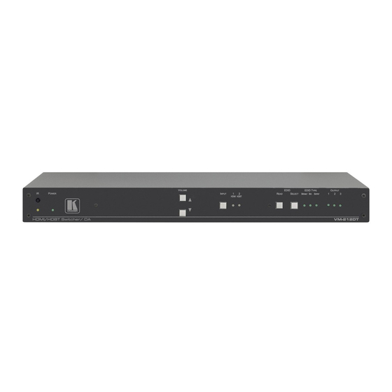
Defining the VM-212DT HDMI/HDBT Switcher/DA Figure 1: VM-212DT HDMI/HDBT Switcher/DA Front Panel Feature Function IR LED Lights yellow when receiving signals from the IR remote sensor IR Remote Control Sensor Sensor for an IR transmitter. IR data is routed according to the IR routing configuration, (see Section 8.6) -
Page 12: Figure 2: Vm-212Dt Hdmi/Hdbt Switcher/Da Rear Panel
Connect to the remote IR sensor/emitter RS-232 DATA 3-pin Terminal Block Connect to the device to be controlled via RS-232 RS-232 CONTROL 3-pin Terminal Block Connect to the serial controller to control the VM-212DT REMOTE 3-pin Terminal Block For future use SETUP 4-way DIP-switch... -
Page 13: Installing In A Rack
Installing in a Rack This section provides instructions for rack mounting the unit. VM-212DT - Installing in a Rack... -
Page 14: Connecting The Vm-212Dt
Figure 3: Connecting the VM-212DT HDMI/HDBT Switcher/DA To connect the VM-212DT, as illustrated in the example in Figure 1. Connect the HDMI source (for example, a Blu-ray disk player) to the IN 1 (HDMI) connector. -
Page 15: Connecting To The Vm-212Dt Via Rs-232
9. Connect the VM-212DT to the mains electricity using the mains cord provided. Connecting to the VM-212DT via RS-232 You can connect to the VM-212DT via an RS-232 connection using, for example, a To connect to the VM-212DT via RS-232: ... -
Page 16: Wiring The Rj-45 Connectors
This section defines the TP pinout, using a straight pin-to-pin cable with RJ-45 connectors. Figure 4: TP PINOUT EIA /TIA 568B Wire Color Orange / White Orange Green / White Blue Blue / White Green Brown / White Brown VM-212DT - Connecting the VM-212DT... -
Page 17: Operating The Vm-212Dt
The EDID can also be modified using EDID Designer. RS-232 and IR Control and Pass-Through The VM-212DT can be controlled via RS-232 and infrared. Depending on how the RS-232 and IR connections are configured, the device either responds to control signals or transparently passes them through to another receiver or transmitter. -
Page 18: Figure 5: Vm-212Dt Rs-232 Control And Pass-Through
7.2.2 Local IR Control and IR Pass-Through Using the VM-212DT The VM-212DT provides an IR sensor and a 3.5mm mini jack for connecting a remote IR emitter or sensor. When the VM-212DT is connected to suitable transmitters and receivers (for example, the TP-580Txr and TP-580Rxr), the VM-212DT can act as a pass-through for IR control signals, allowing remote control of multiple devices using multiple IR remote controllers. -
Page 19: Figure 6: Vm-212Dt Ir Pass-Through Example 1
An LCD display is connected to the TP-580Rxr receiver via an IR emitter Both the TP-580Txr and the TP-580Rxr are connected to the VM-212DT via TP cabling Point the appropriate remote control for the device at the VM-212DT IR sensor to control a device. VM-212DT - Operating the VM-212DT... -
Page 20: Figure 7: Vm-212Dt Ir Pass-Through Example 2
An LCD display is connected to the TP-580Rxr receiver via an IR emitter Both the TP-580Txr and the TP-580Rxr are connected to the VM-212DT via TP cabling Point the LCD display remote control either at the TP-580Txr IR sensor or at the VM-212DT IR sensor to control the LCD display. -
Page 21: Figure 8: Vm-212Dt Ir Pass-Through Example 3
The first DVD player (player 1) is connected to the TP-580Txr transmitter via an IR emitter The second DVD player (player 2) is connected to the VM-212DT via an IR emitter An IR sensor is connected to the TP-580Rxr receiver ... -
Page 22: Operating The Vm-212Dt Remotely Using The Web Pages
Operating the VM-212DT Remotely Using the Web Pages The VM-212DT can be operated remotely using the embedded Web pages. The Web pages are accessed using a Web browser and an Ethernet connection. Before attempting to connect: Ensure that your browser is supported (see Section 10.1) -
Page 23: Figure 10: The Default Page
Figure 10: The Default Page 3. Click OK to continue. The Switching page appears as shown in Figure Figure 11: The Main Switching Page VM-212DT - Operating the VM-212DT Remotely Using the Web Pages... - Page 24 Section 8.5) Data Switching (see Section 8.6) Authentication (see Section 8.7) Device Settings (see Section 8.8) Firmware Upgrade (see Section 8.9) About (see Section 8.10) VM-212DT - Operating the VM-212DT Remotely Using the Web Pages...
-
Page 25: The Switching Page
Audio Output Level Indicates the current audio output level in dB Mute Button Click to mute or unmute the output audio The input selection buttons function as described below. VM-212DT - Operating the VM-212DT Remotely Using the Web Pages... -
Page 26: Figure 13: Input Button
2. Enter the required label. 3. Click Enter or the Save button. Description Label text entry box Save button. Click button to save changes after entering the required label text VM-212DT - Operating the VM-212DT Remotely Using the Web Pages... -
Page 27: The Video And Audio Settings Page
Click enable to de-embed the digital audio Indicator Set Button for 5V Enter the delay in seconds or use the control upon signal increment/decrement buttons, then press Set to save the loss, (see item 1) value VM-212DT - Operating the VM-212DT Remotely Using the Web Pages... -
Page 28: The Output Settings Page
Description Output Label Enter the name required for each output Save Button Click to save the current label Note: Performing a factory reset returns the labels to their default values. VM-212DT - Operating the VM-212DT Remotely Using the Web Pages... -
Page 29: The Edid Management Page
Description File Selector Click to browse saved EDID files on the computer Prevent Modification Click to prevent modification of data Checkbox Default EDID Button Click to read the default EDID VM-212DT - Operating the VM-212DT Remotely Using the Web Pages... - Page 30 2. Click one or more destination Inputs, or select all Inputs by checking the Inputs check-box. All selected Input buttons change color and the EDID summary information reflects the Input selection(s). VM-212DT - Operating the VM-212DT Remotely Using the Web Pages...
- Page 31 Input selection(s). 5. Click the Copy button. The “EDID was copied” success message is displayed and the EDID data are copied to the selected Input(s). 6. Click OK. VM-212DT - Operating the VM-212DT Remotely Using the Web Pages...
-
Page 32: The Data Switching Page
Input 2 to the selected output(s) area RS-232 data Click a box to enable the routing of RS-232 data selection row from the RS-232 Data port to the selected output(s) VM-212DT - Operating the VM-212DT Remotely Using the Web Pages... -
Page 33: Figure 19: Rs-232 Switching Example
IR 3.5mm mini jack on the rear panel to all outputs, (HDBT Output 2, 3, 4, and 5). Figure 20: IR Switching Example VM-212DT - Operating the VM-212DT Remotely Using the Web Pages... -
Page 34: The Authentication Page
Click CHANGE to save the new authentication details Note: If the Authentication page is left open for more than five minutes additional windows may open. After entering your logon credentials, close the other windows. VM-212DT - Operating the VM-212DT Remotely Using the Web Pages... -
Page 35: The Device Settings Page
The Device Settings Page The Device Settings page lets you view and/or modify the device settings, for example, the device name and IP address. Figure 22: The Device Settings Page VM-212DT - Operating the VM-212DT Remotely Using the Web Pages... -
Page 36: Figure 23: The Ip Address Changes Popup Warning
Figure 23 appears because communication will be lost with the device until you enter the new address in your browser. Figure 23: The IP Address Changes Popup Warning VM-212DT - Operating the VM-212DT Remotely Using the Web Pages... -
Page 37: Figure 24: The Factory Reset Popup Warning
1. Click the Factory reset button. The confirmation message shown in Figure 24 is displayed. Figure 24: The Factory Reset Popup Warning 2. Click OK to continue or Cancel to exit the procedure. VM-212DT - Operating the VM-212DT Remotely Using the Web Pages... -
Page 38: The Firmware Upgrade Page
3. Select the required file and click Open. The firmware file name is displayed in the Firmware Upgrade page. 4. Click Start Upgrade. The firmware file is loaded and the warning message shown in Figure 26 appears. VM-212DT - Operating the VM-212DT Remotely Using the Web Pages... -
Page 39: Figure 26: The Firmware Upgrade Warning Popup
Figure 27 appears. Figure 27: The Firmware Upgrade Process Popup Do not interrupt the process or the VM-212DT may be damaged. 7. When the process is complete reboot the device. The firmware is upgraded. VM-212DT - Operating the VM-212DT Remotely Using the Web Pages... -
Page 40: 8.10 The About Us Page
8.10 The About Us Page The VM-212DT About Us page displays the Web page version and Kramer Electronics Ltd company details. Figure 28: The About Us Page VM-212DT - Operating the VM-212DT Remotely Using the Web Pages... -
Page 41: Configuring The Vm-212Dt
IR receiver, try setting the modulation on. Performing a Factory Reset To perform a factory reset of the VM-212DT: 1. Turn off the device. 2. Press and hold the Reset button on the rear of the device. -
Page 42: Technical Specifications
ISTA 1A in carton (International Safe Transit Association) SAFETY REGULATORY COMPLIANCE: ENVIRONMENTAL Complies with appropriate requirements of RoHs and REGULATORY COMPLIANCE: WEEE INCLUDED ACCESSORIES: Power cord Rack “ears” Specifications are subject to change without notice at http://www.kramerelectronics.com VM-212DT - Technical Specifications... -
Page 43: 10.1 Default Ip Parameters
Supported PC Web Browsers Platform Version Windows 7 and Internet Explorer (32/64 bit) version 10 higher Firefox version 30 Chrome version 35 Firefox version 30 Chrome version 35 Safari version 7 Note: Minimum browser window size 1024 x 768 VM-212DT - Technical Specifications... -
Page 44: Default Edid
Default EDID Each input on the VM-212DT is loaded with a factory default EDID. Monitor Model name....VM-212DT Manufacturer..... KMR Plug and Play ID..KMR1200 Serial number.... 295-883450100 Manufacture date..2014, ISO week 255 Filter driver.... None ------------------------- EDID revision.... 1.4 Input signal type.. - Page 45 Front left/right center.. No Rear left/right center... No Rear LFE....No Report information Date generated... 18/02/2016 Software revision..2.60.0.972 Data source....File Operating system..6.1.7601.2.Service Pack 1 Raw data 00,FF,FF,FF,FF,FF,FF,00,2D,B2,00,12,01,01,01,01,FF,18,01,04,80,34,20,78,E2,B3,25,AC,51,30,B4,26, 10,50,54,FF,FF,80,81,8F,81,99,A9,40,61,59,45,59,31,59,71,4A,81,40,01,1D,00,72,51,D0,1E,20,6E,28, 55,00,07,44,21,00,00,1E,00,00,00,FF,00,32,39,35,2D,38,38,33,34,35,30,31,30,30,00,00,00,FC,00,56, 4D,2D,32,31,34,44,54,20,20,20,20,20,00,00,00,FD,00,38,4C,1E,53,11,00,0A,20,20,20,20,20,20,01,DF, 02,03,1B,C1,23,09,07,07,48,10,05,84,03,02,07,16,01,65,03,0C,00,10,00,83,01,00,00,02,3A,80,18,71, 38,2D,40,58,2C,45,00,07,44,21,00,00,1E,01,1D,80,18,71,1C,16,20,58,2C,25,00,07,44,21,00,00,9E,01, 1D,00,72,51,D0,1E,20,6E,28,55,00,07,44,21,00,00,1E,8C,0A,D0,8A,20,E0,2D,10,10,3E,96,00,07,44,21, 00,00,18,00,00,00,00,00,00,00,00,00,00,00,00,00,00,00,00,00,00,00,00,00,00,00,00,00,00,00,00,77 VM-212DT - Default EDID...
-
Page 46: Protocol 3000
Protocol 3000 The can be operated using serial commands from a PC, remote controller or touch screen using the Kramer Protocol 3000. This section describes: Kramer Protocol 3000 syntax (see Section 12.1) Kramer Protocol 3000 commands (see Section 12.2) - Page 47 ( '|' ) character. Message starting character '#' – For host command/query '~' – For device response Device address (Optional, for K-NET) K-NET Device ID followed by '@' Query sign '?' follows some commands to define a query request. VM-212DT - Protocol 3000...
- Page 48 You can directly enter all commands using a terminal with ASCII communications software, such as HyperTerminal, Hercules, etc. Connect the terminal to the serial or Ethernet port on the Kramer device. To enter CR press the Enter key. ( LF is also sent but is ignored by command parser).
-
Page 49: 12.2 Kramer Protocol 3000 Commands
12.2 Kramer Protocol 3000 Commands Command Description Protocol handshaking AUD-LVL Set/get audio level in specific amplifier stage AV-SW-TIMEOUT Set/get video auto-switch timeout BUILD-DATE? Read device build date CPEDID Copy EDID data from the output to the input List files in device... - Page 50 Response ~nn@AUD-LVL␠stage, channel, volume␍␊ Parameters stage - ‘IN, ’OUT’ channel - input or output number volume - audio parameter in Kramer units, minus sign precedes negative values. ++ increase current value, -- decrease current value Response Triggers Notes VM-212DT - Protocol 3000...
- Page 51 Get device build date #BUILD-DATE␍ Response ~nn@BUILD-DATE␠date␠time␍␊ Parameters date - Format: YYYY/MM/DD where YYYY = Year, MM = Month, DD = Day time - Format: hh:mm:ss where hh = hours, mm = minutes, ss = seconds Response Triggers Notes VM-212DT - Protocol 3000...
- Page 52 Response is sent to the com port from which the Set was received (before execution) Notes Destination bitmap size depends on device properties (for 64 inputs it is a 64-bit word) Example: bitmap 0x0013 means inputs 1,2 and 5 are loaded with the new EDID VM-212DT - Protocol 3000...
- Page 53 Public Description Syntax Set: # DPSW-STATUS?␠ dp_sw_id ␍ Get : Get the DIP-switch state Response ~nn @ DPSW-STATUS?␠ dp_sw_id, status␍␊ Parameters dp_sw_id - 1….num of DIP switches status - 0: up 1: down Response Triggers Notes VM-212DT - Protocol 3000...
- Page 54 Response is sent after every change in output HPD status ON to OFF Response is sent after every change in output HPD status OFF to ON and ALL parameters (new EDID, etc.) are stable and valid Notes VM-212DT - Protocol 3000...
- Page 55 Response ~nn@FACTORY␠OK␍␊ Parameters Response Triggers Notes This command deletes all user data from the device. The deletion can take some time. Your device may require powering off and powering on for the changes to take effect. VM-212DT - Protocol 3000...
- Page 56 Command Type - File System Command Name Permission Transparency Set: FS-FREE? Get: Administrator Public Description Syntax Set: Get: Get file system free space #FS-FREE?␍ Response ~nn@FS_FREE␠free_size␍␊ Parameters free_size - free size in device file system in bytes Response Triggers Notes VM-212DT - Protocol 3000...
- Page 57 Response is sent to the com port from which the Set (before execution) / Get command was received Notes For Get, size=0 means EDID is not supported For old devices that do not support this command, ~nn@ ERR 002␍␊ is received VM-212DT - Protocol 3000...
- Page 58 - name of file to get contents contents - byte stream of file contents file_size - size of file (device sends it in response to give user a chance to get ready) Response Triggers Notes VM-212DT - Protocol 3000...
- Page 59 (button press, device menu and similar) or HDCP mode changed Notes Set HDCP working mode on the device input: HDCP supported - HDCP_ON [default] HDCP not supported - HDCP OFF HDCP support changes following detected sink - MIRROR OUTPUT VM-212DT - Protocol 3000...
- Page 60 Response is sent to all com ports after execution if HDCP-STAT was set by any other external control device (button press, device menu and similar) or HDCP mode changed Notes On output – sink status On input – signal status VM-212DT - Protocol 3000...
- Page 61 Get command list or help for specific 1. #HELP␍ Get: command 2. #HELP␠command_name␍ Response 1. Multi-line: ~nn@Device available protocol 3000 commands:␍␊command,␠command…␍␊ To get help for command use: HELP (COMMAND_NAME)␍␊ 2. Multi-line: ~nn@HELP␠command:␍␊description␍␊USAGE:usage ␍␊ Parameters Response Triggers Notes VM-212DT - Protocol 3000...
- Page 62 ~nn@LDEDID␠ERR01␍␊ and returns to the regular protocol mode. If the unit received data that is not a correct packet, it sends the corresponding error and returns to the regular protocol mode. VM-212DT - Protocol 3000...
- Page 63 In each device, some connections can be logged in to different levels and some do not work with security at Connection may logout after timeout The permission system works only if security is enabled with the “SECUR” command VM-212DT - Protocol 3000...
- Page 64 Command Type - System-mandatory Command Name Permission Transparency Set: MODEL? Get: End User Public Description Syntax Set: Get: Get device model #MODEL?␍ Response ~nn@MODEL␠model_name␍␊ Parameters model_name - String of up to 19 printable ASCII chars Response Triggers Notes VM-212DT - Protocol 3000...
- Page 65 - String of up to 14 alpha-numeric chars (can include hyphen, not at the beginning or end) Response Triggers Notes The machine name is not the same as the model name. The machine name is used to identify a specific machine or a network in use (with DNS feature on) VM-212DT - Protocol 3000...
- Page 66 To connect with a randomly assigned IP by DHCP, specify the device DNS name (if available) using the command “NAME”. You can also get an assigned IP by direct connection to USB or RS-232 protocol port if available For proper settings consult your network administrator VM-212DT - Protocol 3000...
- Page 67 Public NET-IP? Get: End User Public Description Syntax Set: Set IP address #NET-IP␠ip_address␍ Get: Get IP address #NET-IP?␍ Response ~nn@ NET-IP␠ip_address␍␊ Parameters ip_address - format: xxx.xxx.xxx.xxx Response Triggers Notes For proper settings consult your network administrator VM-212DT - Protocol 3000...
- Page 68 Set subnet mask #NET-MASK␠net_mask␍ Get: Get subnet mask #NET-MASK?␍ Response ~nn@NET-MASK␠net_mask␍␊ Parameters net_mask - format: xxx.xxx.xxx.xxx Response Triggers The subnet mask limits the Ethernet connection within the local network For proper settings consult your network administrator Notes VM-212DT - Protocol 3000...
- Page 69 Command Type - System-mandatory Command Name Permission Transparency Set: Get: PROT-VER? End User Public Description Syntax Set: Get: Get device protocol version #PROT-VER?␍ Response ~nn@PROT-VER␠3000:version␍␊ Parameters Version - XX.XX where X is a decimal digit Response Triggers Notes VM-212DT - Protocol 3000...
- Page 70 Response Triggers Notes To avoid locking the port due to a USB bug in Windows, disconnect USB connections immediately after running this command. If the port was locked, disconnect and reconnect the cable to reopen the port. VM-212DT - Protocol 3000...
- Page 71 - source id Response Triggers Notes This command replaces all other routing commands The GET command identifies input switching on Step-in clients The SET command is for remote input switching on Step-in clients (essentially via by the Web) VM-212DT - Protocol 3000...
- Page 72 Response Triggers After execution, a response is sent to the com port from which the Get was received Response is sent after every change in input signal status ON to OFF, or OFF to ON Notes VM-212DT - Protocol 3000...
- Page 73 Command Type - System-mandatory Command Name Permission Transparency Set: Get: VERSION? End User Public Description Syntax Set: Get: Get firmware version number #VERSION?␍ Response ~nn@VERSION␠firmware_version␍␊ Parameters firmware_version - XX.XX.XXXX where the digit groups are: major.minor.build version Response Triggers Notes VM-212DT - Protocol 3000...
- Page 74 Video signal lost New video signal detected Audio signal lost Audio signal detected Disable 5V on video output if no input signal detected Video cable unplugged Audio cable unplugged 12.2.4 EDID Source Number Value Input Output Default EDID VM-212DT - Protocol 3000...
- Page 75 Signal or sink is not valid Signal or sink is valid Sink and EDID is valid 12.2.8 Ethernet Port Types Number Value 12.2.9 HDCP Types Number Value HDCP Off HDCP On Follow input Mirror output (“MAC mode”) VM-212DT - Protocol 3000...
- Page 77 SAFETY WARNING Disconnect the unit from the power supply before opening and servicing For the latest information on our products and a list of Kramer distributors, visit our Web site to find updates to this user manual. We welcome your questions, comments, and feedback.
Need help?
Do you have a question about the VM-212DT and is the answer not in the manual?
Questions and answers