
Related Manuals for Kramer VM-24H


Summary of Contents for Kramer VM-24H
-
Page 1: User Manual
K R A ME R E LE CT R O N IC S L T D . USER MANUAL MODEL: VM-24H 2 Input 1:4 HDMI Distributor P/N: 2900-000664 Rev 4... -
Page 3: Table Of Contents
Syntax Instruction Codes Figures Figure 1: VM-24H 2 Input 1:4 HDMI Distributor Front Panel Figure 2: VM-24H 2 Input 1:4 HDMI Distributor Rear Panel Figure 3: Connecting the VM-24H 2 Input 1:4 HDMI Distributor Figure 4: Crossed Cable RS-232 Connection Figure 5: Straight Cable RS-232 Connection with a Null Modem Adapter VM-24H –... -
Page 4: Introduction
Scan Converters and Scalers; GROUP 8: Cables and Connectors; GROUP 9: Room Connectivity; GROUP 10: Accessories and Rack Adapters and GROUP 11: Sierra Products. Congratulations on purchasing your Kramer VM-24H 2 Input 1:4 HDMI Distributor, which is ideal for the following typical applications: •... -
Page 5: Getting Started
Avoid interference from neighboring electrical appliances that may adversely influence signal quality • Position your Kramer VM-24H away from moisture, excessive sunlight and dust This equipment is to be used only inside a building. It may only be connected to other equipment that is installed inside a building. -
Page 6: Safety Instructions
Kramer Electronics has made arrangements with the European Advanced Recycling Network (EARN) and will cover any costs of treatment, recycling and recovery of waste Kramer Electronics branded equipment on arrival at the EARN facility. For details of Kramer’s recycling arrangements in your particular country go to our recycling pages at http://www.kramerelectronics.com/support/recycling/. -
Page 7: Overview
The infrared remote extension cable transmitter, see Section 3.2 • RS-232 serial commands transmitted by a touch screen system, PC, or other serial controller Defining the VM-24H 2 Input 1:4 HDMI Distributor This section defines the VM-24H. VM-24H - Overview... -
Page 8: Figure 1: Vm-24H 2 Input 1:4 Hdmi Distributor Front Panel
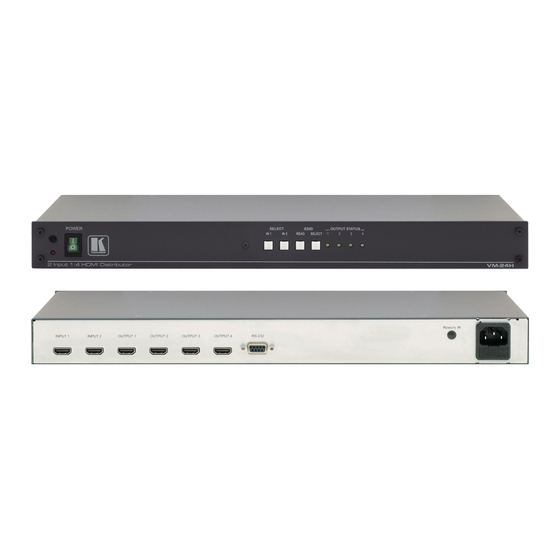
Figure 1: VM-24H 2 Input 1:4 HDMI Distributor Front Panel Feature Function IR Receiver The red LED is illuminated when receiving signals from the Kramer infrared remote control transmitter POWER Switch Illuminated switch for turning the unit ON or OFF SELECT IN 1 Button... -
Page 9: Figure 2: Vm-24H 2 Input 1:4 Hdmi Distributor Rear Panel
Figure 2: VM-24H 2 Input 1:4 HDMI Distributor Rear Panel Feature Function INPUT 1 HDMI Connector Connects to the HDMI source 1 INPUT 2 HDMI Connector Connects to the HDMI source 2 OUTPUT HDMI Connectors Connects to the HDMI acceptor (from 1 to 4) -
Page 10: Using The Ir Transmitter
This distance can be extended to up to 60 meters when used with three extension cables (Model: C-A35M/A35F-50). Before using the external IR receiver, be sure to arrange for your Kramer dealer to insert the internal IR connection cable (P/N: 505-70434010-S) with the 3.5mm connector that fits into the REMOTE IR opening on the rear panel. -
Page 11: Installing In A Rack
Installing in a Rack This section provides instructions for rack mounting the unit. VM-24H - Installing in a Rack... -
Page 12: Connecting The Vm-24H
Connecting the VM-24H Always switch off the power to each device before connecting it to your VM-24H. After connecting your VM-24H, connect its power and then switch on the power to each device. To connect the VM-24H, as illustrated in the example in... -
Page 13: Figure 3: Connecting The Vm-24H 2 Input 1:4 Hdmi Distributor
Figure 3: Connecting the VM-24H 2 Input 1:4 HDMI Distributor VM-24H - Connecting the VM-24H... -
Page 14: Operating The Vm-24H
Operating the VM-24H This section describes how to: • Control the VM-24H via RS-232, see Section 6.1 • Operate the VM-24H, see Section 6.2 • Use the EDID button, see Section 6.3 Controlling via RS-232 You can connect to the unit via a crossed RS-232 connection, using for example, a PC. -
Page 15: Operating The Vm-24H
The EDID acquired is a weighted average of all the connected outputs. For example, if several displays with different resolutions are connected to the outputs, the acquired EDID supports all the resolutions, as well as other parameters included in the EDID. VM-24H - Operating the VM-24H... - Page 16 4. Press the EDID READ button to copy the EDID of the selected OUTPUT to the inputs. If you want to cancel the EDID modification, wait for a few seconds without touching any button VM-24H - Operating the VM-24H...
- Page 17 The new EDID is copied when both buttons no longer illuminate. 6.3.2 Acquiring the Default EDID To reset to the default EDID (the factory-default programmed into the VM-24H before it is shipped), do the following: 1. Connect the power supply.
-
Page 18: Technical Specifications
WEIGHT: 2.5kg (5.5lbs) approx. ACCESSORIES: Power cord, rack “ears”, null-modem adapter, Windows®- based control software, infrared remote control transmitter OPTIONS: External remote IR receiver cable (P/N: C-A35M/IRR-50) Specifications are subject to change without notice at http://www.kramerelectronics.com VM-24H - Technical Specifications... -
Page 19: Communication Protocol
The default data rate is 9600 baud, with no parity, 8 data bits and 1 stop bit. Note: Compatibility with Kramer’s Protocol 2000 does not mean that a machine uses all of the commands below. Each machine uses a sub-set of Protocol 2000, according to its needs. -
Page 20: Instruction Codes
For example, instruction 1 (SWITCH VIDEO) causes all units (including audio, data, etc.) to switch. Similarly, if a machine is in FOLLOW mode, it performs any video instruction. VM-24H - Communication Protocol... - Page 21 For example, to set the audio gain (instruction 22) of output 3 to 681dec (2A9hex), send HEX code: followed by HEX code: To set the audio gain of output 6 to 10013dec (271Dhex), send HEX code: followed by HEX code: VM-24H - Communication Protocol...
- Page 23 For the latest information on our products and a list of Kramer distributors, visit our Web site where updates to this user manual may be found. We welcome your questions, comments, and feedback. Web site: www.kramerelectronics.com E-mail: info@kramerel.com SAFETY WARNING...
Need help?
Do you have a question about the VM-24H and is the answer not in the manual?
Questions and answers