HP MSM720 Installation Manual
Hide thumbs
Also See for MSM720:
- Installation manual (33 pages) ,
- Specification (27 pages) ,
- Quick start manual (6 pages)
Table of Contents
Advertisement
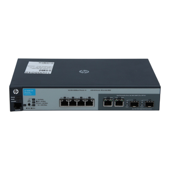
HP MSM720 Controllers Installation Guide
Abstract
This document describes how to install and initially configure the MSM720 Controllers. This document applies to the MSM720
Access Controller [J9693A, J9695A (TAA)] and the MSM720 Premium Mobility Controller [J9694A, J9696A (TAA)]. These
products are hereafter referred to as controller.
HP Part Number: 5998-7935
Published: June 2015
Edition: 1 (Software Version 6.6.0.0)
Advertisement
Table of Contents

Related Manuals for HP MSM720


Summary of Contents for HP MSM720
- Page 1 HP MSM720 Controllers Installation Guide Abstract This document describes how to install and initially configure the MSM720 Controllers. This document applies to the MSM720 Access Controller [J9693A, J9695A (TAA)] and the MSM720 Premium Mobility Controller [J9694A, J9696A (TAA)]. These products are hereafter referred to as controller.
- Page 2 © Copyright 2013, 2015 Hewlett-Packard Development Company, L.P. The information contained herein is subject to change without notice. The only warranties for HP products and services are set forth in the express warranty statements accompanying such products and services. Nothing herein should be construed as constituting an additional warranty. HP shall not be liable for technical or editorial errors or omissions contained herein.
-
Page 3: Table Of Contents
Using the console port......................7 2 Installing the controller................8 Installing the controller......................9 Installing optional accessories....................16 3 Configuring the controller................17 Initial configuration.........................17 4 Support and other resources..............19 Online documentation......................19 Contacting HP........................19 HP websites...........................19 Typographic conventions......................19 A Specifications..................20 Physical..........................20 Electrical..........................20 Environmental........................20 Acoustic..........................20 Safety...........................20 Emissions..........................20... -
Page 4: Product Overview
1 Product overview Package contents Unpack your controller and verify that you have received these items: Controller External AC/DC power adapter AC/DC power adapter power cable (for your region) Console port serial cable (DB-9 to RJ-45) Documentation Software License, Warranty, and Support information Accessory kit comprised of: ◦... - Page 5 The controller is beginning its boot sequence. Turns on for three seconds at power up or reset. Locator (blue) The locator LED is used to locate a specific MSM720 in an area in which multiple controllers are installed. The LED can be set to be Use the command Flashing chassislocate to set the LED status to on or flashing for a specified number of minutes (1- 1 440).
-
Page 6: Restarting The Controller
Resetting the controller to factory defaults HP recommends that you use the web interface to reset the controller to factory defaults as follows: Simplified UI Select Views > Software Settings > Backup & Restore > Restore. -
Page 7: Using The Console Port
Alternatively, to reset the controller to its factory default configuration: Using a paperclip, press and release the Reset button. Immediately press and hold the Clear button until the LEDs above the Clear button flash three times, then release the Clear button. Using the console port The console port is used to connect a console to the controller with the supplied RJ-45 to DB9 cable. -
Page 8: Installing The Controller
The mark is your assurance that the power cable can be used safely with the controller. If the supplied power cable does not fit, contact HP Networking support. -
Page 9: Installing The Controller
CAUTION: Use only the AC/DC power adapter and power cable supplied with the controller. Use of other adapters or power cables, including those that came with other HP Networking products, can result in damage to the equipment. Installing the controller... - Page 10 AC/DC power adapter is connected to the controller and the adapter power cable is connected to a power source. The external AC/DC power adapter automatically adjusts to any voltage between 100–240 volts and either 50 or 60 Hz. The MSM720 cannot be powered by Power over Ethernet (PoE).
- Page 11 When the self-test completes successfully: The Power LED remains on. The Fault, Locator and Test LEDs are off. The Act LED remains on indicating the default port LED mode. The port LEDs on the front of the controller go into their regular operational mode: ◦...
- Page 12 Hold the controller with attached brackets up to the rack and move it vertically until the rack holes line up with the bracket holes, and then insert and tighten the four number 12-24 screws holding the brackets to the rack. Figure 6 Mounting in a rack Wall installation WARNING!
- Page 13 Attach the controller to the wall or wood surface with two 15.9 mm (5/8 inch) number 12 wood screws (not included). Figure 7 Wall mounting the controller Installing the controller on a horizontal surface For tabletop use, attach the provided rubber feet to the four underside corners of the controller. To reduce risk of someone tripping on the cables, consider anchoring the cables to a table leg.
- Page 14 You can install or remove an optional mini-GBIC from a mini-GBIC slot without having to power off the controller. Use only HP mini-GBICs. Mini-GBIC information Dual-personality ports use either the 10/100/1000Base-T RJ-45 connector, or a supported HP mini-GBIC (Small Form Factor Pluggable (SFP)) for fiber-optic connection. By default, the RJ-45 connectors are enabled.
- Page 15 Hot swapping of transceivers is supported. If you install or remove a transceiver with the controller powered on, a reset will not occur. However, HP recommends that you not perform rapid hotswaps. Wait a few seconds for the Mode LED to turn on and then turn off (during initialization).
-
Page 16: Installing Optional Accessories
Installing optional accessories Two optional controller accessories are available: HP X510 1U Cable Guard (J9700A): Mounts to the front of the controller to help stabilize and support the networking cables and provide extra security against tampering or theft. HP X520 1U Power Adapter Shelf (J9701A): Holds the power supply adapter at the back of the controller. -
Page 17: Configuring The Controller
On the Login page, enter admin for both Username and Password, and then select Login. A workflow to set initial controller settings starts automatically. After you accept the HP Licence, read the instructions and respond to the prompts on each page, and select Next to continue to the next workflow page. - Page 18 Select Let’s try it out to switch to the Simplified UI. The Simplified UI provides access to the most commonly configured controller options, and features wizards to make configuration tasks easy. For initial configuration of the controller, HP recommends using the Simplified UI. The first time the Simplified UI starts, it shows the product tour, which provides a quick overview of the key features of the interface.
-
Page 19: Support And Other Resources
4 Support and other resources Online documentation You can download documentation from the HP Support Center website at: www.hp.com/support/ manuals. Search by product number or name. The following documents provide related information: MSM Controllers Configuration Guide MSM7xx Controllers Release Notes... -
Page 20: A Specifications
A Specifications Physical Width Depth Height Weight 25.4 cm (10 in) 16.5 cm (6.5 in) 4.4 cm (1.73 in) 0.91 kg (2.25 lbs) Electrical AC voltage Maximum current Frequency range 100-240 volts .24A 50/60 Hz Environmental Operating Non-Operating Temperature 5°C to 45°C (41°F to 1 13°F) -40°C to 70°C (-40°F to 158°F) Relative humidity (non-condensing) 15% to 95% at 40°C (104°F) -
Page 21: Ethernet
ESD: IEC 61000-4-2 Radiated: IEC 61000-4-3 EFT/Burst: IEC 61000-4-4 Surge: IEC 61000-4-5 Conducted: IEC 61000-4-6 Power frequency magnetic field: IEC 61000-4-8 Voltage dips and interruptions: IEC 61000-4- 1 1 Harmonics: EN 61000-3-2, IEC 61000-3-2 Flicker: EN 61000-3-3, IEC 61000-3-3 Ethernet Four RJ-45 auto-sensing 10/100/1000 (IEEE 802.3 Type 10Base-T, IEEE 802.3u Type 100Base-TX, IEEE 802.3ab Type 1000Base-T);... -
Page 22: Cabling Specifications
Cabling specifications Twisted-pair 10 Mbps Category 3, 4 or 5, 100-ohm unshielded twisted-pair (UTP) or shielded twisted-pair copper Operation (STP) cable, complying with IEEE 802.3 10BASE-T specifications. 100 Mbps Category 5, 100-ohm UTP or STP cable, complying with IEEE 802.3u 100BASE-TX Operation specifications. - Page 23 Multimode fiber modal Technology Supported cable type bandwidth Supported distances 1000-BX single mode fiber 0.5 - 10,000 meters *For distances less than 20km, a 10dB attenuator must be used. For distances between 20km and 40km, a 5dB attenuator must be used. Attenuators can be purchased from most cable vendors. Cabling distance specifications...
-
Page 24: B Mode Conditioning Patch Cable (Fiber Cables)
Installing the patch cable As shown in the illustration below, connect the patch cable to the HP transceiver with the section of single mode fiber plugged in to the Tx (transmit) port. Then, connect the other end of the patch cable to your network cabling patch panel, or directly to the network multimode fiber. -
Page 25: C Regulatory Information
For important information, see the Safety, Compliance, and Warranty Information document that shipped with your controller. Also see Safety and Compliance Information for Server, Storage, Power, Networking, and Rack Products, available at http://www.hp.com/support/ Safety-Compliance-EnterpriseProducts. FCC Class A Notice...
Need help?
Do you have a question about the MSM720 and is the answer not in the manual?
Questions and answers