Table of Contents
Advertisement
Quick Links
Model No. WEEMSY61000
Serial No.
The serial number is found in the
location shown below. Write the
serial number in the space above.
QUESTIONS?
As a manufacturer, we are com-
mitted to providing complete
customer satisfaction. If you have
questions, or if there are missing
parts, we will guarantee complete
satisfaction through our
Customer Service Department.
Please CALL:
0345-089009
Or WRITE:
ICON Health & Fitness Ltd.
Revie Road Industrial Estate
Revie Road
Leeds
LS11 8JG
CAUTION
Read all precautions and instruc-
tions in this manual before using
this equipment. Save this manu-
al for future reference.
Serial
Number
Decal
®
USERʼS MANUAL
www.weiderfitness.com
w
Visit our website at
Advertisement
Table of Contents

Subscribe to Our Youtube Channel
Related Manuals for WeiderPro weiderpro 9930


Summary of Contents for WeiderPro weiderpro 9930
- Page 1 ® USERʼS MANUAL Model No. WEEMSY61000 Serial No. The serial number is found in the location shown below. Write the serial number in the space above. Serial Number Decal QUESTIONS? As a manufacturer, we are com- mitted to providing complete customer satisfaction.
-
Page 2: Table Of Contents
Table of Contents Important Precautions ..............3 Before You Begin . -
Page 3: Important Precautions
Important Precautions WARNING: To reduce the risk of serious injury, read the following important precau- tions before using the home gym. 1. It is the responsibility of the owner to ensure are raised. The weights will fall with great that all users of the home gym are adequate- force. -
Page 4: Before You Begin
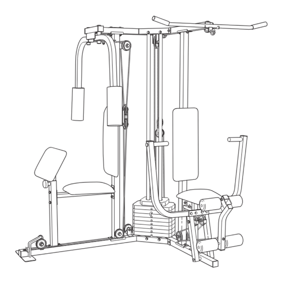
Before You Begin Thank you for selecting the innovative and versatile have additional questions, please contact our Customer Service Department at 0345-089009. To WEIDER PRO 9930 home gym. The WEIDER ® ® 9930 offers a unique selection of weight stations help us assist you, please note the product model designed to develop every major muscle group of the number and serial number before calling. -
Page 5: Assembly
Assembly Make Assembly Easier for Yourself! • Two (2) adjustable wrenches • One (1) standard screwdriver Everything in this manual is designed to ensure that the home gym can be assembled • One (1) phillips screwdriver successfully by anyone. Before beginning assembly, make sure to read the informa- •... -
Page 6: With Two 5/16" X 2 3/4" Bolts (20), Two 5/16" Flat
Frame Assembly 1. Before beginning, make sure that you have read and understood the information on page 5. Locate and open the parts bag labelled “FRAME ASSEMBLY.” Press a 2” Square Inner Cap (38) into the Butterfly Base (61). Press two 2” Square Inner Caps (38) into the Press Base (60). -
Page 7: With Two 5/16" X 2 3/4" Bolts (20), Two 5/16" Flat
3. Place two Weight Bumpers (84) over the indicated holes in the Butterfly Base (61). Slide the Weight Guides (58) into the indicated holes. Attach the Weight Guides (58) to the Butterfly Base (61) with two 3/8” x 2 1/2” Bolts (6), four 3/8” Flat Washers (17), and two 3/8”... -
Page 8: With Two 5/16" X 2 3/4" Bolts (20), Two 5/16" Flat
6. Hold the Butterfly Top Frame (64) and the Press Top Frame (63) on the indicated brackets on the Uprights (59, 62) and the Weight Guides (58). Note: Before attaching the Top Frames to the Uprights, make sure that both Weight Guides (58) are positioned inside of the indicated holes. -
Page 9: With Two 5/16" X 2 3/4" Bolts (20), Two 5/16" Flat
Arm Assembly 9. Locate and open the parts bag labelled “ARM ASSEMBLY.” Lubricate See the inset drawing. Orient the Press Frame (53) as shown. Lubricate a 3/8” x 8” Bolt (30). Attach the Press Frame to the Press Base (60) with the Bolt, two 1”... -
Page 10: Bracket
12. Press two 1 1/2” Square Inner Caps (79) into the Leg Lever (49). Insert a Bumper (33) between the brackets on the Leg Lever (49). Secure the Bumper to the Leg Lever with a #10 x 1” Screw (32). Slide the bracket on the Leg Lever (49) onto the Press Seat Frame (52). -
Page 11: Bracket
15. Wrap the Short Cable over a “V” Pulley (21) as shown. Attach the “V” Pulley and a Long Cable Trap (14) to one side of the welded bracket on the Butterfly Upright (62) with a 3/8” x 2 1/2” Bolt (6) and a 3/8” Nylon Locknut (4). -
Page 12: Bracket
19. Wrap the Medium Cable (72) over a 4 1/2” Pulley (34) in the direction shown. Attach the Pulley to the Butterfly Top Frame (64) with a 3/8” x 1 3/4” Bolt (22) and a 3/8” Nylon Locknut (4). 20. Attach the threaded shaft on the Medium Cable (72) to the Small “U”-Bracket (43) with a 1/4”... -
Page 13: Bracket
22. Wrap the Long Cable (73) around a 3 1/2” Pulley (5) in the direction shown. Attach the Pulley and a Cable Trap (39) to the Butterfly Upright (62) with a 3/8” x 3 3/4” Bolt (7), a 3/8” Flat Washer (17), and a 3/8” Nylon Locknut (4). -
Page 14: The Press Base (60)
25. Note: For clarity, this and the following drawings show some parts removed. Remove the lower 3 1/2” Pulley (5) from the Double “U”-Bracket (36). Then, wrap the Long Cable (73) over the Pulley (5) in the direction shown. Attach the Pulley to the Double “U”-Bracket (36) with a 3/8”... -
Page 15: Lever (49)
29. Wrap the Long Cable (73) around a “V”-Pulley (21) in the direction shown. Attach the “V”-Pulley and a Large Cable Trap (14) to the small tube on the Press Seat Frame (52) with a 3/8” x 3 1/4” Bolt (28), a 3/8” Flat Washer (17) and a 3/8”... - Page 16 Seat Assembly 33. Locate and open the parts bag labelled “SEAT ASSEMBLY.” Insert a 1/4” x 2” Carriage Bolt (85) through the cen- tre hole in a Seat Plate (42). Attach the Seat Plate to a Seat (51) with two 1/4” x 3/4” Screws (13). Insert the 1/4”...
- Page 17 36. Insert a 1/4” x 1 1/2” Carriage Bolt (82) through the centre hole in a Seat Plate (42). Attach the Seat Plate to a Seat (51) with two 1/4” x 3/4” Screws (13). Insert the 1/4” x 1 1/2” Carriage Bolt (82) into the indi- cated hole in the Seat Bar (74) and secure it with a 1/4”...
- Page 18 39. Apply the WEIDER PRO 9930 decal in the location shown. WEIDER PRO 9930 40. Make sure that all parts have been properly tightened. The use of the remaining parts will be explained in ADJUSTMENT, beginning on page 21 of this manual. Before using the home gym, pull each cable a few times to make sure that the cables move smoothly over the pulleys.
-
Page 19: Cable Diagrams
Cable Diagrams The Cable Diagrams below and on the next page show the proper routing of the Short Cable (71), the Medium Cable (72), and the Long Cable (73). The numbers show the correct route for each Cable. Make sure that the Cables are routed correctly, that the Pulleys move smoothly, and that the Cable Traps do not touch or bind the Cables. - Page 20 Long Cable (73)
-
Page 21: Adjustment
Adjustment The instructions below describe how each part of the home gym can be adjusted. IMPORTANT: When using an attachment, make sure it is in the correct starting position for the exercise to be performed. If there is any slack in the cables or chain as an exercise is performed, the effectiveness of the exercise will be reduced. -
Page 22: Trouble-Shooting And Maintenance
Trouble-shooting and Maintenance Inspect and tighten all parts each time you use the home gym. Replace any worn parts immediately. The home gym can be cleaned using a damp cloth and mild non-abrasive detergent. Do not use solvents. TIGHTENING THE CABLES The type of cable used on the home gym can stretch slightly when it is first used. -
Page 23: Weight Resistance Chart
Weight Resistance Chart The chart below shows the approximate weight resistance at each exercise station. “Top” refers to the 6 lb. top weight; the other numbers refer to the 12.5 lb. weight plates. Note: The actual resistance at each station may vary due to differences in individual weight plates as well as friction between the cables, pulleys, and weight guides. - Page 24 Part Identification Chart–Model No. WEEMSY61000 R0101A 1/4" Flat Washer (11) 5/16" x 1 3/4" Bolt (9) 5/16" Flat Washer (19) 5/16" x 2 1/2" Bolt (3) 5/16" x 2 3/4" Bolt (20) 3/8" Flat Washer (17) 5/16" x 2 1/2" Carriage Bolt (1) 1/4"...
- Page 25 1/4" x 1 1/2" Screw (88) 1/4" x 1 1/2" Carriage Bolt (82) 3/8" x 1" Bolt (15) "V" Pulley (21) (Not shown to scale) 3/8" x 1 3/4" Bolt (22) 3 1/2" Pulley (5) (Not shown to scale) 3/8" x 2" Bolt (35) 4 1/2"...
- Page 26 3/4" Round Inner Cap (40) 1" x 7/8" Plastic Bushing (29) 1" Round Cap (26) 1" Round Inner Cap (41) 1" Inner Cap (80) 1 3/4" Square Inner Cap (37) 1 1/2" Square Inner Cap (79) 2" Square Inner Cap (38)
-
Page 27: Bracket
Part List—Model No. WEEMSY61000 R0201A Key No. Qty. Description Key No. Qty. Description 5/16” x 2 1/2” Carriage Bolt Foam Pad 5/16” Nylon Locknut Pad Tube 5/16” x 2 1/2” Bolt Leg Lever 3/8” Nylon Locknut Lat Bar 3 1/2” Pulley Seat 3/8”... - Page 28 Exploded Drawing—Model No. WEEMSY61000 R0201A...
-
Page 29: Ordering Replacement Parts
Ordering Replacement Parts If you encounter any problems with this product, or if you need to order replacement parts, contact the ICON Health & Fitness Ltd. office, or write: ICON Health & Fitness Ltd. Unit 4 Revie Road Industrial Estate Revie Road Leeds LS11 8JG...
Need help?
Do you have a question about the weiderpro 9930 and is the answer not in the manual?
Questions and answers