
Related Manuals for HIGHLEAD HLK-1510


Summary of Contents for HIGHLEAD HLK-1510
-
Page 1: Instruction Manual
HLK-1510 ELECTRONIC PATTERN SEWING MACHINE Instruction Manual Parts Catalog SHANGHAI HUIGONG NO.3 SEWING MACHINE FACTORY From the library of: Superior Sewing Machine & Supply LLC... - Page 2 YOUR YOUR SAFETY! SAFETY! FOR YOUR YOUR SAFETY! SAFETY! If you operate the sewing machine first time,please make sure to read the following instructions for your safety and proper operation. CAUTION CAUTION CAUTION CAUTION In this technical manual。the notice is mentioned at some paragraph to attract your attention for the safety.Please keep it in mind whenever you work with the sewing machine....
- Page 3 Caution ★ For avoiding the sewing machine from the troubles,please do not operate the sewing machine under the following conditions. Temperature and humidity During operating: The atmosphere temperature should not exceeded more 350 ℃(95 °F) or less 5°C(41°F). During transportation: The atmosphere temperature should not exceeded more 55°C(131°F) or less -10°C(18°F).
-
Page 4: Table Of Contents
----- CONTENTS ----- STRUCTURE OF THE SEWING MACHINE ....................1 SPECI FICATION ............................2 INSTALLATION ............................. 3 3-1 Installation of the control box ........................... 3 3-2 Installation of the power switch ........................3 3-3 Installation of the oil pan ..........................3 3-4 Installation of the sewing machine head ...................... - Page 5 7-9 Adjustment of the work holder ........................20 7-10 Adjustment of the trimmer cam follower ....................... 20 7-11 Adjustment of the position for the movable knife point .................. 21 7-12 Adjustment of the fixed knife position ......................21 7-13 Adjustment of the thread take up spring swing stroke ..................22 7-14 Adjustment of the thread take up spring tension .....................
-
Page 6: Structure Of The Sewing Machine
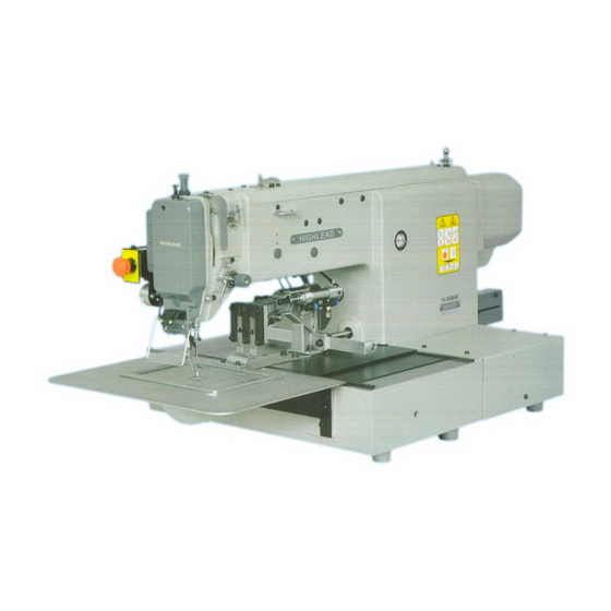
1 STRUCTURE OF THE SEWING MACHINE HLK-1510 electronic pattern sewing machine is constructed with the following main parts ○ ②Thread st and ③O perat i on Panel ④C ont rol U ni t 1 Sewing machine head ⑤H al t sw i t ch ⑥W ork holder foot switch... -
Page 7: Speci Fication
2 SPECI FICATION Sewing area: X-Direction(left/right) 100mm Y-Direction(forward/backward) 100mm Maximum sewing speed: 2500 rpm Sewing speed: 10 steps variable from 200 to 2500 rpm Stitch length: 0.1 to 12.7mm Stitch type: Single needle lock stitch Needle bar stroke : 41.2 mm Thread take up lever stroke:... -
Page 8: Installation
3 INSTALLATION Caution ★ The machine should be installed by the specialists who have enough experience for the sewing machine installations. ★ All the necessary electric wiring should be done by electric engineers who are qualified for the electric wiring. ★... -
Page 9: Installation Of The Sewing Machine Head
3-4 Installation of the sewing machine head Caution ★ For the safety,please make sure to carry the sewing machine head by more than two people. (1) Make sure to hold the machine table with the caster stopper. ○ (2) Fit the rubber cushion pads 3 into the ○... -
Page 10: Connection Of The Operation Panel
3-6 Connection of the operation panel Please connect the operation panel with the instructions of operation panel manual enclosed in the packing. 3-7 Connection of the electric cables Please make sure to ground place where there mark. Failure to do so cause electric shock... -
Page 11: Installation Of The Thread Stand
3-8 Installation of the thread stand (1) Assemble thread stand with the instructions enclosed in the packing. (2) thread ○ stand in the thread stand holeg tabletop. (3) thread ○ 1 firmly from the stand rear side of the table with tightening ○... -
Page 12: Lubrication
4 LUBRICATION Caution ★Please make sure to turn power switch off before oiling. ★Please make sure to put some oil before starting the operation of the brand new machine or NOTE : Please use high quality white machining oil. 4-1 Filling the oil tank Pour the oil through the oil ○... -
Page 13: Threading The Upper Thread
5-2 Threading the upper thread ★ Please make sure to turn the power switch off before threading the upper thread. ★ Please thread the upper thread with referring to the below figures. 5-3 Winding the bobbin thread ★Please make sure to pull the upper thread out of the needle before winding the bobbin thread (1) Turn the power switch ON.... -
Page 14: Settling The Bobbin
(5) Pass through the thread from the thread ○ stand 4 as shown on the right figure . then , wind the thread to the empty ○ bobbin 5 in the arrow mark “a” direction couple times and insert the ○... -
Page 15: Setting The Bobbin Case
5-5 Setting the bobbin case ○ . (1) Set the needle bar to its highest position then,open the cylinder cover ○ ○ 3 . (2) Open the bobbin case latch lever 2 fully then,fit it securely in the inner hook [NOTE]Please pull the bobbin thread about 2.5mm out of the thread hole(NO.4)of the bobbin case.... -
Page 16: The Sewing Operation
home position. ○ (left)is pressed again,the operation will start . (4) When the start switch Caution ★ Depending on the shape of the work holder,the collision may be happened with the work holder and the presser foot while the work holder is on the way back to the home position.For avoidance of this accident, before starting the sewing operation . -
Page 17: Adjustment Of The Thread Tension
(5) Back to the interface of data input, press ,then enter the Sewing Interface(the background color is blue) ○ (6) When the start switch 2 (left) is ○ pressed,the work holder 3 will go down ,the operation will start . For the details ,please refer instructions on the... -
Page 18: Standard Adjustment
thread tension becomes tight if turn it to the clockwise. (2) Upper thread tension Adjust the upper thread tension based on the bobbin thread tension.For this adjustment,turn the thread ○ tension adjusting nut○ 3 .The upper tread tension becomes tight if turn the thread tension adjusting nut 3 to the clockwise,and the upper thread tension becomes loose if turns it to the counter clock wise.... -
Page 19: Adjustment Of The Position Between The Needle And The Shuttle Hook
7-2 Adjustment of the position between the needle and the shuttle hook (1) Turn the power switch OFF. (2) Turn the sewing machine pulley by ○ hand then,move up the needle bar from the lowest position and stop it at ○... -
Page 20: Adjustment Of The Clearance Between The Driver And The Needle
7-4 Adjustment of the clearance between the driver and the needle (1) Please take the same procedures as above paragraph 7-2.from(1)to(5). (2) Please make sure the clearance between the shuttle hook point and the needle has been adjusted 0.05~0.1 mm at above procedure Adjustment clearance between the shuttle hook and... -
Page 21: Adjustment Of The Presser Foot
7-6 Adjustment of the presser foot [NOTE]The presser foot is a very important part to form the fine stitches. It moves simultaneously with the needle and stabilize the needle penetrating area of the sewing material with pressing down it,when the needle sticks into or pulls out the sewing material and prevent the skip stitch or the over penetration happening.Please adjust the presser foot properly to the sewing materials with the following instructions.... - Page 22 [NOTE]If the thickness of the sewing material changes very often,it is recommended to takethe easy way for the adjustment of the presser foot position with the method thatchange only the fixed position of the presser foot after fixed the presser foot bar at higher position. For this ○...
- Page 23 7.6.3 Adjustment of the presser foot timing [NOTE] The presser foot up and down movement during the sewing synchronizes with the needle up and down movement. With changing this synchronized timing to the sewing materials, the skip stitches can be prevented or the seam tightness can be improved. For example,...
-
Page 24: Adjustment Of The Wiper
7-7 Adjustment of the wiper ○ (1) Loosen the wiper setscrew 3 and ○ adjust the wiper 1 to be positioned ○ where the wiper 1 passes under the ○ needle point 2 with about 2 mm clearances right after the sewing machine is stopped running at the needle upper position (the thread take up lever's highest position).... -
Page 25: Adjustment Of The Work Holder
○ ○ the bobbin winder and put the empty bobbin 5 on the rotating shaft 6 then,push the adjusting ○ lever 1 to the arrow direction “a”. Secondary. move the whole bobbin winder to the arrow direction ○ “C” and stop it at the position where the empty bobbin is rotated then,tighten the setscrews ○... -
Page 26: Adjustment Of The Position For The Movable Knife Point
(2) Under the sewing machine regular stop condition(the needle stop position is upper and the take up lever ○ ○ stop position is highest),loosen the setscrew 5 of the cam follower lever 4 and adjust the cam ○ ○ ○ follower 2 to be positioned to contact with the shoulder portion 3 of the trimmer cam... -
Page 27: Adjustment Of The Thread Take Up Spring Swing Stroke
○ . plate ○ (5) After the adjustment,tighten the setscrews securely. (6) Put all the parts for this adjustment back to the original locations. 7-13 Adjustment of the thread take up spring swing stroke ○ ○ Loosen the setscrew 2 and turn the whole thread tension regulator 3 then,adjust the thread take up spring swing stroke to be become 9 to 10mm.... -
Page 28: Adjustment Of The Upper Thread Tension Release
7-17 Adjustment of the upper thread tension release [NOTE] (a) The upper thread tension release works when the upper thread is trimmed automatically or the presser foot is lifted during the work holder feeding. (b) If the upper thread tension release does not work properly when the upper thread is trimmed automatically, the thread tail from the needle becomes shorter then, it induces the skip stitch happening or pulling the thread tail out of the needle at the start of the sewing. - Page 29 (1) Turn the power switch ON and cancel the sewing area limit with the operation panel. (2) After the cancellation of the sewing area limit, once. Turn the power switch OFF. 7-18-1. Shifting the mechanical home position to the X direction (1) Remove the X-Y cover (right),(left) and X cover.
-
Page 30: Adjustment Of The X-Y Table Contact Pressure
7-18-2.Shifting the mechanical home position to the Y direction ○ . (1) Loosen the Y-detector setscrew ○ (2) lf move the Y-detector to the front,the mechanical home position is shifted to the backward.If it is moved to the backward.the mechanical home position is shifted to the front. ○... -
Page 31: Maintenance
○ (2) Loosen four setscrews 1 of the ○ Y-stepping motor adapter ○ (3) Press the Y-motor adapter to arrow direction lightly. ○ (4) Fasten the setscrews securely, and put the motor cover to original position. NOTE After the adjustment, please make sure that there is no gap in the gear mechanism. -
Page 32: Bad Sewing Condition&Its Cause And Rem Edy
9 BAD SEWING CONDITION&ITS CAUSE AND REM EDY [NOTE]Please fix the troubles during the sewing machine operation with referring to the following instructions.Beside,if the trouble conditions are not coming under these classification,please contact the sewing machine dealers nearby. Cause Remedy Ref. - Page 33 Cause Remedy Ref. page & condition item Too short bobbin thread by Use non racing spring with bobbin — bobbin spinning after trimming Bobbin thread tension is too Loosen bobbin thread tension spring tight Skip stitch Thread tail from needle is Decrease pre-tension 7-16 happens at...
- Page 34 Cause Remedy Ref.page & condition item Upper thread tension is not Increase upper thread tension tight enough Adjust tension regulator position 7-17 Thread tension regulator’s properly discs are opened during Adjust upper tension release position 7-17 sewing properly Stitch forming Presser foot position is not Adjust presser foot position properly is loose...
- Page 35 Cause Remedy Ref. page & item condition X-Y detectors cable are Connect X-Y cables precisely — disconnected X-Y detectors cable are Change them new detectors — Work holder does out of order no stop at home Detector detector Adjust the clearance properly 7-19 position plate clearance is too big...
-
Page 36: Arm Bed &It's Accessories(一
A.ARM BED &IT'S ACCESSORIES(一) — 31 — From the library of: Superior Sewing Machine & Supply LLC... - Page 37 A.ARM BED &IT'S ACCESSORIES(一) Fig. Part No. Description Pcs. Remarks HK41B88001 Type plate H924025050 Ф2.5×5 HK42C58001 Motor cover HK41B98001 Plate H6642B8001 Screw M4×8 HM019B8001 Arm plate HA307B0674 Rubber plug HM015B8001 Bracket HA104G0654 Screw 1/8(44)×6 H6671B8001 Hinge HA100C2190 Screw 11/64(40)×8 HM014B8001 Plate H6675B8001 Plate...
- Page 38 A.ARM BED &IT'S ACCESSORIES(一) Fig. Part No. Description Pcs. Remarks H6665B8001 Screw M4×30 H6664B8001 Ball bushing H415050180 Screw M5×18 HK42B58001 Cover HK45B18001 Cover H661EB8001 Screw M4×6 H6613I7102 Connector panel H6642B8001 Screw M4×8 HK44B38001 Cover — 33 — From the library of: Superior Sewing Machine & Supply LLC...
-
Page 39: Arm Bed &It's Accessories(二
B. ARM BED &IT'S ACCESSORIES(二) — 34 — From the library of: Superior Sewing Machine & Supply LLC... - Page 40 B.ARM BED &IT'S ACCESSORIES(二) Fig. Part No. Description Pcs. Remarks HA115B0709 HA115B0708 Screw HA310B0703 Regulator casing HA115B0701 Screw HA115B0706 Thread take-up spring HA310B0705 Thread tension discs HA310B0702 Disc retaining plate H6675C8001 Thread tension spring HA115B7010 Thumb nut revolution stopper HA310B0701 Thumb nut H660GB8001 Thumb nut...
- Page 41 B.ARM BED &IT'S ACCESSORIES(二) Fig. Part No. Description Pcs. Remarks HE121B8001 Spacer H6756B8001 Knife H6698B8001 Screw M3×6 HA310B0705 Thread tension discs — 36 — From the library of: Superior Sewing Machine & Supply LLC...
-
Page 42: Sewing Mechanism(一
C. SEWING MECHANISM(一) — 37 — From the library of: Superior Sewing Machine & Supply LLC... - Page 43 C. SEWING MECHANISM(一) Fig. Part No. Description Pcs. Remarks H2009B0743 Felt H2009B0742 Felt H6616B8001 Felt H6617B8001 Bushing H2009B0731 Felt H6616B8001 Felt H6620B8001 Bushing H431050100 Screw M5×10 H3208H0661 Ball bearing H3416D0692 Screw 15/64(28)×8 H6612B8001 Needle bar bushing(upper) H6613B8001 Needle bar bushing(lower) HK40C58001 Drive shaft H6607C8001...
- Page 44 C. SEWING MECHANISM(一) Fig. Part No. Description Pcs. Remarks HA108C0663 Screw SM1/4(40)×7 HK42C98001 Hand wheel H609030120 HK43C18001 Shaft H4767E8001 Spring HK43C08001 Bushing H5311F8001 Screw 11/64(40)×6.1 H415030100 Screw M3×10 HF15401014 Bearing HF15401012 Washer HA108C0662 Screw 1/4(40)×5 HA113D2122 Gear H431050080 Screw M5×8 H3205J0661 Bushing H6606F8001...
-
Page 45: Sewing Mechanism(二
D. SEWING MECHANISM(二) — 40 — From the library of: Superior Sewing Machine & Supply LLC... - Page 46 D. SEWING MECHANISM(二) Fig. Part No. Description Pcs. Remarks HA304G0656 Screw 3/16(28)×15 H6634C8001 Felt H6628C7101 Connecting rod assy H6628B8001 Bushing H2010J0066 9/32(28) H431050050 Screw H6630C8001 Screw 9/32(28) H6635C8001 Rock shaft H431050080 Screw M5×8 H6670C8001 Collor HA305E0662 Screw SM15/64(28)×4.5 H6631C8001 Sector gear H6627B8001 Oil braid H2009B0743...
-
Page 47: X-Y Table Mechanism(一
E. X-Y TABLE MECHANISM(一) — 42 — From the library of: Superior Sewing Machine & Supply LLC... - Page 48 E.X-Y TABLE MECHANISM(一) Fig. Part No. Description Pcs. Remarks HK42D38001 Cover HA70264C06 Screw 9/64(40)×8 H7351C8001 Washer H415040080 Screw M4×8 HK42D18001 Cover HK42D08001 Screw M3×6 HK41D78001 Rear stopper Y HK42D48001 Cover H103040080 Bolt M4×8 H431030060 Screw M3×6 H416040100 Screw M4×10 HK41D18001 Fixed race Y HK41D08001 Retainer Y...
-
Page 49: X-Y Table Mechanism(二
F.X-Y TABLE MECHANISM(二) — 44 — From the library of: Superior Sewing Machine & Supply LLC... - Page 50 F.X-Y TABLE MECHANISM(二) Fig. Part No. Description Pcs. Remarks H415050100 Screw M5×10 H6686D8001 Washer H6646D8001 Motor mounting plate Y H6632D8001 Screw M4×6 H6631D8001 Gear HK43D08001 Stepping motor HK43D08001 Stepping motor H415040120 Screw M4×12 HK46D68001 Rack Y H415050160 Screw H6649D8001 Rack adapter Y H6623B8001 Ball bushing 10 H6693D8001...
-
Page 51: Cable Component & Detector Mechanism
G. CABLE COMPONENT & DETECTOR MECHANISM — 46 — From the library of: Superior Sewing Machine & Supply LLC... - Page 52 G. CABLE COMPONENT & DETECTOR MECHANISM Fig. Part No. Description Pcs. Remarks H6656D8001 Detector X mounting plate H6657D8001 Bracket H6677D8001 H6694D8001 Detector X H6695D8001 Screw H415040080 Screw M4×8 H415040080 Screw M4×8 H6642B8001 Screw M4×8 H6679D8001 Nylon clip AB-3N H6665D8001 Detector bracket Y H6676D7101 Holder plate assy H415030100...
-
Page 53: Work Holder Mechanism(Air Operated)
H. WORK HOLDER MECHANISM(AIR OPERATED) — 48 — From the library of: Superior Sewing Machine & Supply LLC... - Page 54 H. WORK HOLDER MECHANISM(AIR OPERATED) Fig. Part No. Description Pcs. Remarks HM012E8001 Work holder guide base H005001080 Washer H007013060 E-type retaining ring Link HA719B7010 Washer HA700F2100 Screw SM11/64(40)×7 Link Link HA719B7010 Washer HA700F2100 Screw SM11/64(40)×7 Link HF15404017 Bracket H415040080 Screw M4×8 HF15404016 retaining ring...
- Page 55 H. WORK HOLDER MECHANISM(AIR OPERATED) Fig. Part No. Description Pcs. Remarks H415050140 Screw M5×14 H6686D8001 Washer — 50 — From the library of: Superior Sewing Machine & Supply LLC...
-
Page 56: Presser Foot Mechanism
J. PRESSER FOOT MECHANISM — 51 — From the library of: Superior Sewing Machine & Supply LLC... - Page 57 J. PRESSER FOOT MECHANISM Fig. Part No. Description Pcs. Remarks H2010J0065 Screw 9/32(28)×35 H2010J0066 9/32(28) HM018F8001 Bracket H6682D8001 Screw M4×10 HM022F8001 Presser spring H2000J2040 Presser bar HM016F8002 Screw 1/4(40) HM015F8001 Positioning block HM016F8001 Screw 1/4(40) HM014F8001 Link HM011F8001 Link HM013F8001 Link H431040100 Screw...
-
Page 58: Presser Bar Lifting Mechanism
K. PRESSER BAR LIFTING MECHANISM — 53 — From the library of: Superior Sewing Machine & Supply LLC... - Page 59 K. PRESSER BAR LIFTING MECHANISM Fig. Part No. Description Pcs. Remarks HA700I2070 HA100H2050 Screw 15/64(28) HA107H1012 HM036F8001 Link HA107H1013 Screw HA107H0662 Screw 3/16(28) HK43F48001 Lever HK44F17101 Solenoid H007013040 E-type retaining ring HK44F68001 Link HM048F8001 Bushing HK44F88001 Link H431050080 Screw M5×8 HK45F38001 HM037F8001 H415050200...
-
Page 60: Thread Trimming Mechanism
L. THREAD TRIMMING MECHANISM — 55 — From the library of: Superior Sewing Machine & Supply LLC... - Page 61 L. THREAD TRIMMING MECHANISM Fig. Part No. Description Pcs. Remarks HM038E8001 Screw 11/64(40) HA712N6912 Screw 1/8(44)×7 HA712N6911 Plate HM010G8001 Plate HM011G8001 Link HA111G0683 Screw 11/64(40)×12 H6683D8001 H6613F8001 Spring washer H6685D8001 Washer H415040100 Screw M4×10 H003002050 HZ11040080 Screw M4×8 HK43G57101 Soft cord HK43G38001 Bracket HM012G7101...
- Page 62 L. THREAD TRIMMING MECHANISM Fig. Part No. Description Pcs. Remarks H6692B8001 Screw 9/64(40)×3.2 H3405D0663 Knuckle joint H6671F8001 Movable knife H6679F8001 Washer H6678F8001 Screw 11/64(40) H6692B8001 Screw 9/64(40)×3.2 H6680F8001 Spring H007013025 E-type retaining ring H6667F8001 Tension rod H6659F8001 Screw 11/64(40)×10 H431050060 Screw M5×6 H6664F8001...
-
Page 63: Wiper Mechanism
M. WIPER MECHANISM — 58 — From the library of: Superior Sewing Machine & Supply LLC... - Page 64 M. WIPER MECHANISM Fig. Part No. Description Pcs. Remarks H6642B8001 Screw M4×8 H6682D8001 Screw M4×10 HM019H7101 Wire assy HM013H8001 Frame H6642I8001 Washer HK41H57101 Frame assy H668CE8001 Washer H668BE8001 Spring washing H003002030 HM009H8001 Link H6643C8001 Screw 1/8(44)×4.5 HM031H8001 Link HM024H7101 Frame HM028H8001 Shaft H431030040...
-
Page 65: Oil Lubrication Mechanism
N. OIL LUBRICATION MECHANISM — 60 — From the library of: Superior Sewing Machine & Supply LLC... - Page 66 N. OIL LUBRICATION MECHANISM Fig. Part No. Description Pcs. Remarks H6614H8001 Oil gauge H6613H8001 Pipe H3200G2030 Holder HM008I8001 Holder H6634H8001 Felt H6642B8001 Screw M4×8 H6611H8001 Holder H6646H8001 Felt H2000M0090 HK40I97101 Oil pipe assy HK41I37101 Oil pipe assy HM005I7101 Oil pipe assy HM062E8001 Frame H6682D8001...
-
Page 67: Accessories
R. ACCESSORIES — 62 — From the library of: Superior Sewing Machine & Supply LLC... - Page 68 R. ACCESSORIES Fig. Part No. Description Pcs. Remarks H3200L0070 Hexagonal wrench 1/16" 1/16" HB01001015 Hexagonal wrench 1.5 HB01001025 Hexagonal wrench 2.5 HB01001030 Hexagonal wrench 3 HB01001040 Hexagonal wrench 4 HA300J2070 Screw driver(large) HA300J2200 Screw driver(middle) HA300J2210 Screw driver(small) H2004O0069 Oiler with oil HA300J2220 Spanner 10-14 H6685C8001...
- Page 69 ADD: 1418, Yishan Road, Shanghai, China Zip Code: 201103 Overseas Business: TEL: 86-21-64853303 FAX: 86-21-64854304 E-mail:highlead@online.sh.cn http://www.highlead.com.cn The description covered in this manual is subject to change for improvement of the commodity without notice 2009.10. Printed From the library of: Superior Sewing Machine & Supply LLC...
Need help?
Do you have a question about the HLK-1510 and is the answer not in the manual?
Questions and answers