
Related Manuals for HIGHLEAD HLK-03


Summary of Contents for HIGHLEAD HLK-03
- Page 1 HLK-03 Electronic Direct Drive Bar Tacker Machine Instruction Manual Parts Catalog SHANGHAI BIAOZHUN HAILING SEWING MACHINERY CO., LTD.
- Page 2 FOR YOUR SAFETY! If you operate the sewing machine first time,please make sure to read the following instructions for your safety and proper operation. CAUTION In this technical manual,the notice is mentioned at some paragraph to attract your attention for the safety.Please keep it in mind whenever you work with the sewing machine....
- Page 3 ENVIRONMENT STANDARD Caution ★ For avoiding the sewing machine from the troubles,please do not operate the sewing machine under the following conditions. Temperature and humidity During operating: The atmosphere temperature should not exceeded more 350℃(95°F) or less 5°C(41°F). During transportation: The atmosphere temperature should not exceeded more 55°C(131°F) or less -10°C(18°F).
-
Page 4: Table Of Contents
----- CONTENTS ----- 1 STRUCTURE OF THE SEWING MACHINE ..................1 2 SPECI FICATION ............................2 3 INSTALLATION ............................3 3-1 Installation of the control box ........................3 3-2 Installation of the power switch ........................3 3-3 Connection of the foot switch ........................4 3-4 ... - Page 5 7-8 Adjustment of the trimmer cam follower ....................18 7-9 Adjustment of the position for the movable knife point ................19 7-10 Adjustment of the fixed knife position ...................... 19 7-11 Adjustment of the thread take up spring swing stroke ................20 7-12 Adjustment of the thread take up spring tension ..................
-
Page 6: Structure Of The Sewing Machine
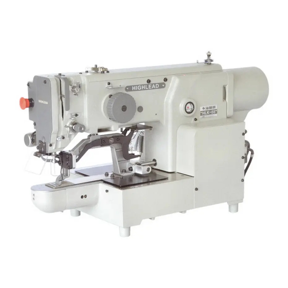
② ① ⑤ ⑦ ③ ④ ⑧ ⑥ HLK-03 electronic bar tack machine is constructed with the following main parts ○ ②Thread stand ③Operation Panel ④Control Unit 1 Sewing machine head ⑤Halt switch ⑥Work holder foot switch ⑦Wooden Table ⑧Steel stand... -
Page 7: Speci Fication
2 SPECI FICATION Sewing area: X-Direction(left/right) 30mm Y-Direction(forward/backward) 30mm Maximum sewing speed: 2000 rpm Sewing speed: variable from 200 to 2000 rpm Stitch length: 0.1 to 12.7mm Stitch type: Single needle lock stitch Needle bar stroke : 41.2 mm Thread take up lever stroke: 68mm Class of needle:... -
Page 8: Installation
3 INSTALLATION Caution ★ The machine should be installed by the specialists who have enough experience for the sewing machine installations. ★ All the necessary electric wiring should be done by electric engineers who are qualified for the electric wiring. ★... -
Page 9: Connection Of The Foot Switch
3-3 Connection of the foot switch ○ ○ Connect the foot switch 6 to the control box 7 .The foot switch is enclosed in the accessory box. 3-4 Installation of the oil pan ○ (1) Fix the oil pan 1 at its four corners on the table top with four 3-5 Installation of the sewing machine head Caution ★... -
Page 10: Installation Of The Spindle Motor
3-6 Installation of the spindle motor Reference to the controller using the instructions in section 2.2 debug mode, enter "CP-1", the screen shows " CP-1", press key to enter the CP-1,then press P1 and P2 at the same time to adjust the parameters of the spindle motor ,Which is in number 6 point test content. -
Page 11: Connection Of The Electric Cables
3-8 Connection of the electric cables Please make sure to ground the place where there is a mark. Failure to do so may cause electric shock and/or malfunction. - Page 12 (1) Connect the machine head and the control box with cables as shown on the figure. (2) Hold the dangling cables under the table with accessory tie holders and cord ties. (3) At this time, please check whether the cables are not pulled when tilting the sewing machine. (4) Control box back and socket as shown on the below figure (5) Printed circuit board wiring as shown on the below figure Upper...
-
Page 13: Installation Of The Thread Stand
3-9 Installation of the thread stand (1)Assemble the thread stand with the instructions enclosed in the packing. ○ (2) Fit the thread stand 1 in the thread stand holeg on the tabletop. ○ (3) Fix the thread stand 1 firmly from the rear side of the table with tightening the nut ○... -
Page 14: Proper Operation
5 PROPER OPERATION 5-1 Installation of the needle Caution ★Please make sure to turn the power switch OFF before installing or replacing the needle. ★Please pay attention for the fingers not to be wounded by the needlepoint. ○ (1) Loosen the needle set screw 1 then,... -
Page 15: Winding The Bobbin Thread
5-3 Winding the bobbin thread ★Please make sure to pull the upper thread out of the needle before winding the bobbin thread. (1) Pass through the thread from the thread ○ stand 4 as shown on the right figure . then,... -
Page 16: Setting The Bobbin Case
5-5 Setting the bobbin case ○ 1 . (1) Set the needle bar to its highest position then,open the cylinder cover ○ ○ 3 . (2) Open the bobbin case latch lever 2 fully then,fit it securely in the inner hook [NOTE]Please pull the bobbin thread about 2.5cm out of the thread hole of the bobbin case.... -
Page 17: The Sewing Operation
perform position with key, and re-start by means of the start switch. Press key to perform thread trimming, and press again key to return to the origin. ※ Note: When sewing machine stops by pressing key, if you press key again, the machine will perform trimming. -
Page 18: Adjustment Of The Thread Tension
6-3 Adjustment of the thread tension The thread tension between the upper and bosom thread should be balanced in the best condition. When the upper thread tension is well balanced with the bobbin thread tension,both threads are interlocked along the centerline of fabric layers as shown on the below figures. NOTE Normally weaker bobbin thread tension brings better sewing quality.... -
Page 19: Standard Adjustment
7 STANDARD ADJUSTMENT Caution ★Please make sure to turn the power switch OFF before adjust the sewing machine. ★If the adjustment is required under the power switch is ON,keep the start foot switch away from the foot. ★Be careful not to be wounded by the needle or the inner hook point. ★Please make sure to put the safety guards(Eye guard,... -
Page 20: Adjustment Of The Clearance Between The Shuttle Hook And The Needle
○ ○ 6 . (5) Turn the hook retainer lever 5 then,remove the hook retainer ○ ○ ○ (6) Loosen the driver setscrew 9 then,move the driver 10 and adjust the shuttle hook point 7 to be ○ matched with the center line 8 of the needle.... -
Page 21: Adjustment Of The Thread Guide
7-6 Adjustment of the thread guide ○ ○ ○ (1) Remove the E-shaped snap ring 3 which is engaging the movable knife 2 and the link 1 then, loosen ○ ○ 5 . the setscrews 4 and remove the sliding plate(S) ○... -
Page 22: Adjustment Of The Bobbin Winder
7-7 Adjustment of the bobbin winder (1) Adjustment of the winding volume ○ ○ Loosen the setscrew 2 of the adjusting lever 1 and adjust the position of the adjusting ○ ○ 1 .If move the adjusting lever lever 1 to the arrow direction “a” the Winding volume is reduced, ○... -
Page 23: Adjustment Of The Trimmer Cam Follower
★ When the clamp goes down, the clearance between the pressure plate (NO.1) and the roller (NO.2) should be adjusted more than 1mm. ○ (1) Turn the power switch off. And remove two springs ○ (2) Loosen four setscrews ○ (3) Put the clamps (right / left) 5 down. -
Page 24: Adjustment Of The Position For The Movable Knife Point
(2) Under the sewing machine regular stop condition(the needle stop position is upper and the take up lever ○ ○ stop position is highest),loosen the setscrew 5 of the cam follower lever 4 and adjust the cam ○ ○ ○ follower 2 to be positioned to contact with the shoulder portion 3 of the trimmer cam... -
Page 25: Adjustment Of The Thread Take Up Spring Swing Stroke
○ position to be positioned for the blade edge 7 to have the clearance 0.5mm from the edge of the needle ○ 8 . plate ○ (5) After the adjustment,tighten the setscrews 9 securely. (6) Put all the parts for this adjustment back to the original locations. 7-12 Adjustment of the thread take up spring swing stroke ○... -
Page 26: Adjustment Of The Upper Thread Tension Release
7-16 Adjustment of the upper thread tension release [NOTE] (a) If the upper thread tension release does not work properly when the upper thread is trimmed automatically, the thread tail from the needle becomes shorter then, it induces the skip stitch happening or pulling the thread tail out of the needle at the start of the sewing. -
Page 27: 7-17Adjustment Of The X-Y Table Contact Pressure
7-16-1. Shifting the mechanical home position to the X direction (1) Remove the X-Y cover (right),(left) and X cover. ○ ○ (2) Loosen the detector plate fix screws(2 pieces) 1 . if move the detector plate 2 to the right, the mechanical home position is shifted to the left and if it is moved to the left, the mechanical home position is shifted to the right. -
Page 28: 7-18Adjustment Of The X -Y T Stepping Motor Position
of control on the X-Y table movement. (1) Remove the right and left cover of the machine bed casting. ○ ○ (2) Loosen the setscrew(2 pieces) 2 so that the X fixed race 1 can be moved slightly. ○ 3 ,the X table contact pressure is (3) If tighten the both right and left contact presser adjusting screws increased.... -
Page 29: Maintenance
7-20 7-18-2 Adjustment of Y stepping motor position (1) Remove the motor cover. ○ (2) Loosen four setscrews 1 of the ○ Y-stepping motor adapter ○ (3) Press the Y-motor adapter 2 to arrow direction lightly. ○ (4) Fasten the setscrews 1 securely, and put the motor cover to original position. -
Page 30: Bad Sewing Condition&Its Cause And Remedy
9 BAD SEWING CONDITION&ITS CAUSE AND REMEDY [NOTE]Please fix the troubles during the sewing machine operation with referring to the following instructions.Beside,if the trouble conditions are not coming under these classification,please contact the sewing machine dealers nearby. Cause Remedy Ref. page & condition item Poor thread tension... - Page 31 Cause Remedy Ref. page & condition item Too short bobbin thread by Use non racing spring with bobbin — bobbin spinning after trimming Bobbin thread tension is too Loosen bobbin thread tension spring tight Thread tail from needle is Decrease pre-tension 7-13 very short after trimming Skip stitch...
- Page 32 Cause Remedy Ref. page & condition item Upper thread tension is not Increase upper thread tension tight enough Adjust tension regulator position 7-15 Thread tension regulator’s properly discs are opened during Adjust upper tension release position 7-15 sewing Stitch forming properly is loose Needle and shuttle hook is...
- Page 33 Cause Remedy Ref. page & item condition Detector and detector plate Check setscrews and tighten them 7-17 mounting is loose securely Detector and detector plate Work holder Adjust detector and detector plate clearance is bigger than 7-17 stops at not clearance properly standard original home...
- Page 62 SHANGHAI BIAOZHUN HAILING SEWING MACHINERY CO., LTD. ADD: NO.850 Shulin Road, Songjiang District Shanghai, P.R.China Zip Code: 201612 Overseas Business: TEL: 86-21-64853303 FAX: 86-21-64854304 E-mail:sales@highlead.com.cn http://www.highlead.com.cn The description covered in this manual is subject to change for improvement of the commodity without notice 2018.5. Printed...
Need help?
Do you have a question about the HLK-03 and is the answer not in the manual?
Questions and answers