
Related Manuals for HIGHLEAD HLK-3020


Summary of Contents for HIGHLEAD HLK-3020
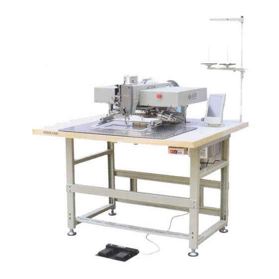
- Page 1 HLK-3020 (TH) ELECTRONIC PATTERN SEWING MACHINE Instruction Manual Parts Catalog SHANGHAI BIAOZHUN HAILING SEWING MACHINERY CO., LTD.
-
Page 2: Table Of Contents
CONTENTS FOR YOUR SAFETY………………………………………………………………1 USE OF THE ENVIRONMENT……………………………………………………2 1. STRUCTURE OF HLK-3020(TH) SEWING MACHINE……………………3 2. SPECIFICATION………………………………………………………………3 3. INSTALLATION…………………………………………………………………4 3-1.Installation of the control box…………………………………………………4 3-2.Installation of the power switch………………………………………………4 3-3.Connection of the foot switch…………………………………………………5 3-4.Installation of the sewing machine head………………………………………5 3-5.Connection of electric cables…………………………………………………6 3-6.Installation of spool stand………………………………………………………7... -
Page 3: For Your Safety
FOR YOUR SAFETY! If you operate the sewing machine first time,please make sure to read the following instructions for your safety and proper operation. CAUTION In this technical manual。the notice is mentioned at some paragraph to attract your attention for the safety.Please keep it in mind whenever you work with the sewing machine. CAUTION is used as the notice to warn a possible danger to cause a wound This technical manual explains the instructions how to operate and maintain the sewing... -
Page 4: Use Of The Environment
USE OF THE ENVIRONMENT Caution ★ For avoiding the sewing machine from the troubles,please do not operate the sewing machine under the following conditions. Temperature and humidity During operating: The atmosphere temperature should not exceeded more 350℃(95°F) or less 5°C(41°F). During transportation:... -
Page 5: Structure Of Hlk-3020(Th) Sewing Machine
1. STRUCTURE OF HLK-3020(TH) SEWING MACHINE 2. SPECIFICATION Sewing area: X-Direction(left/right) 300mm Y-Direction(forward/backward) 200mm Maximum sewing speed: 800 rpm Sewing speed: variable from 100 to 800 rpm Stitch length: 0.1 to 12.7mm Stitch type: Single needle lock stitch — —... -
Page 6: Installation
Needle bar stroke : 56mm Thread take up lever stroke: 96mm DY×3 26# (the standard specification) Class of needle: Presser foot lift: 20 mm Presser foot alternation: Variable from 4mm to 10mm Work holder lift: 30mm Hook: Large size shuttle hook Lubrication system: Manual oiling and replenishment with the oil wicks from the oil tanks Lubrication oil:... -
Page 7: 3-3.Connection Of The Foot Switch
(1) Mount the power switch①with the wood screw②underneath the table as shown on the figure. (2) Fix the electric cords with the staples③ underneath the table. (3) Connect the plug⑧of the power switch① to the control box⑦. (4) Attach the power plug⑤to another end of the power switch cord④.... -
Page 8: 3-5.Connection Of Electric Cables
3-5.Connection of electric cables (1) Connection diagram (2) Back of control box and sockets diagram. SOCKET NAME FOR CONNECTING TO Spindle motor power Spindle motor signal RS-232C(Optional) Operation panel Foot switch pedal Solenoid output RS-232C(Optional) Control signal 1 Extension I/0 Control signal 2 Y stepping motor X Stepping motor... -
Page 9: 3-6.Installation Of Spool Stand
(3)Circuit board diagram. Control signal Pneumatic Pneumatic Trimmer Presser frame 1 ,X11 inner foot presser frame solenoid solenoid Thread wiper solenoid Inner foot solenoid Thread release Control signal Emergency Shaft shaft solenoid 2 ,X9 switch detector detector 3-6.Installation of spool stand (1)... -
Page 10: Oiling
4 . OILING CAUTION ★ Turn of power witch before oiling。 ★ Oil the machine sufficiently before first operation of a brand new machine or after long time stop. NOTE : Please use high quality white SF machining oil: Pour some oil into red marked oil holes as the figure on the right shows.... -
Page 11: 5-3.Winding The Bobbin Thread
★ Please refer to the figure on the right and thread the upper thread as the figure shows. 5-3.Winding the bobbin thread ★Please be sure to pull the upper thread out of the needle before winding the bobbin thread. (1) Turn the power switch ON. (2) Entering winding model with refering to the Instruction manual of control systerm. -
Page 12: Proper Sewing
6. PROPER SEWING 6-1.Operation of the emergency switch If an incident such as thread breakage,needle breakage and any other accident happen during the sewing operation,please hit the emergency switch immediately.The sewing machine will be stopped instantly. Caution ★ Before start the sewing operation,please check the location of the emergency switch and keep in mind the function and operation method of it.... -
Page 13: 6-3.Adjustment Of The Thread Tension
6-3.Adjustment of the thread tension The thread tension between the upper and bottom thread should be balanced. When the upper thread tension is well balanced with the bobbin thread tension, both threads are interlocked along the centerline of fabric layers as shown on the below figures. Note: Thread tension should be adjusted to fit different fabrics. -
Page 14: 7-1.Adjusting Of Needle Bar Height
7-1.Adjusting of needle bar height When needle bar touch shuttle hook point②,the distance between top of the needle hole and shuttle hook point should be about 2.5mm. To adjust height of needle bar. (1) Loosen screw③. (2) Adjusting the height of needle bar ④. -
Page 15: 7-4.Adjustment Of The Presser Foot
7-4.Adjustment of the presser foot [NOTE]The presser foot is a very important part for performing fine stitches. It moves simultaneously with the needle. When the needle sticks into or pulls out the sewing material, the inner foot must press down on sewing material and stabilize the needle penetrating area to prevent the skip stitch or the over penetration happening.Please adjust the presser foot properly to the sewing materials with the following instructions.... -
Page 16: 7-5.Adjustment Of The Mechanical Home Position
7-5.Adjustment of the mechanical home position [NOTE]The mechanical home position is set at the center of the sewing area as default. Note: The second mechanical home position can be set with referring to Operation Manual of control system. 7-5-1.Shifting the mechanical home position along X direction (1) Loosen the set screws①(2 pieces) of X-detector plate ③, Move the detector plate ③... -
Page 17: 7-6.Adjustment Of X And Y Timing Belt Tension
7-6.Adjustment of X and Y timing belt tension (1) Remove the Left cover (big) and Right cover (big) from machine head. (2) Loosen nut② and set screws of pulley base③. (3) Tighten or loosen screw ① to increase or decrease tension of X Timing belt. Tighten or loosen screw ⑦ to adjust tension of X Timing belt (short). -
Page 18: Parts Catalog
A.ARM BED AND ITS ACCESSORIES — 16 — — 16 —... - Page 19 A.ARM BED AND ITS ACCESSORIES Fig. Part No. Description Pcs. Remarks HBB3252072 Arm and bed H6623C8001 Screw HBB3265081 Big slide plate H6675F8001 Screw HBB3266081 Needle plate H6675B8001 Retainer plate HBB3274081 Guide plate H6671B8001 Hinge HA104G0654 Screw HM015B8001 Guide plate base H9010B8001 Screw SM1/4(40)×2.5 H9011B8001 Needle bar bushing...
- Page 20 A.ARM BED AND ITS ACCESSORIES Fig. Part No. Description Pcs. Remarks H3410C301K Screw SM9/64(40)×6.5 H7257B8001 Screw H7258B8001 Nut SM1/8(44) H7259B8001 Tension spring H7260B8001 Tension disc H7261B8001 Thread tension regulator complete base HA7311CC06 Screw SM9/64(40)×6 H7262B8001 Thread guide H3410C301K Screw H9016B8001 Face plate H7238B8001 Screw SM15/64(28)×22 H3410C301K Screw...
- Page 21 B.NEEDLE BAR AND THREAD TAKE-UP MECHANISM — 19 — — 19 —...
- Page 22 B.NEEDLE BAR AND THREAD TAKE-UP MECHANISM Fig. Part No. Description Pcs. Remarks H2000C2040 Pulley HA110D0672 Screw HBC3258081 Servomotor HBC3252081 Arm shaft H9004C8001 Collar HA105D0662 Screw SM1/4(40)×6 H7209C8001 Thread take-up cam H7210C8001 Screw H403060120 Screw GB/T68 M6×12 H4933K8001 Screw SM1/4(40)×10 H602040450 Pin GB/T117 4×45 H7211C8001 Thread take-up lever H7212C8001 Screw...
- Page 23 B.NEEDLE BAR AND THREAD TAKE-UP MECHANISM Fig. Part No. Description Pcs. Remarks HK42C47101 Shaft connector Assy. HA104F0654 Screw H3207C0671 Timing belt pulley (a) H3205C0661 Stop ring HBC3255081 Servomotor base H415060200 Screw M6×20 H007007320 Stop ring HB6296E081 Bearing 6201DU φ12×φ32×10 H415050120 Screw M5×12 HBC3257081 Bearing pedestal —...
- Page 24 C.LOWER SHAFT MECHANISM — 22 — — 22 —...
- Page 25 C.LOWER SHAFT MECHANISM Fig. Part No. Description Pcs. Remarks H7204D8001 Eccentric H7205D8001 Set screw SM15/64(28)×12 H7206D8001 Pin H415060250 Screw GB/T70.1 M6×25 H4728H8001 Washer H7237D8001 Bearing K43×48×17(NTN) H7207D8001 Eccentric cover H2000B2050 Screw SM11/64(40)×9 H7208D8001 Crank connecting rod H7209D8001 Crank connecting rod pin H7210D8001 Pin H7211D8001 Screw SM3/16(32)×18...
- Page 26 C.LOWER SHAFT MECHANISM Fig. Part No. Description Pcs. Remarks H2405D0664 Set screw SM15/64(28)×14 H7240D7101 Shuttle hook KSP-204N — 24 —...
- Page 27 D.CENTER PRESSER FOOT MECHANISM — 25 — — 25 —...
- Page 28 D.CENTER PRESSER FOOT MECHANISM Fig. Part No. Description Pcs. Remarks H415040100 Screw M4×10 HBE3251081 Inner foot H7220F8001 Presser bar guide bracket H7222F8001 Screw H7221F8001 Connecting rod H7207I8001 Screw H7206I8001 Knee lifter lever base HA300J2280 Screw H7205I8001 Screw H7204I8001 Knee lifter lever H8906I8001 Air cylinder link GB/T 6173 M10×1.25 H005008100 Spring washer...
- Page 29 E.UPPER FEED LIFTING ROCK SHAFT MECHANISM — 27 — — 27 —...
- Page 30 E.UPPER FEED LIFTING ROCK SHAFT MECHANISM Fig. Part No. Description Pcs. Remarks H7204G8001 Presser foot lifting eccentric HA307C0066 Screw SM1/4(40)×6 H7205G8001 Eccentric wheel rod H7206G8001 Screw H7207G8001 Washer H7208G8001 Nut SM11/32(28) H7209G8001 Adjusting crank H7210G8001 Screw SM5/16(18)×18 H7211G8001 Presser foot lifting shaft H7212G8001 Presser foot lifting shaft crank H415060140 Screw M6×14...
- Page 31 F.Y MECHANISM(1) — 29 — — 29 —...
- Page 32 F.Y MECHANISM(1) Fig. Part No. Description Pcs. Remarks HBG3252081 Base plate supportor (big) HBG3251081 Base plate H415060200 Screw M6×20 H415050160 Screw M5×16 H415040120 Screw M4×12 HBG3270081 Y-shaft stop pole H415050120 Screw M5×12 H415040080 Screw M4×8 HBG3269081 Link plate HBG3272072 Y-shaft slide rail Assy. HBG3253081 Base plate supportor (small) HBG3284081 Y-shaft stop pole (short) HBG3274081 Guide sleeve supportor...
- Page 33 G.Y MECHANISM(2) — 31 — — 31 —...
- Page 34 G.Y MECHANISM(2) Fig. Part No. Description Pcs. Remarks HBG3264081 Pulley shaft (long) H415050160 Screw M5×16 HBG3285081 Y-stepping motor H431050060 Screw M5×6 HBG3257081 Stepped shaft HBG3266081 Shaft connector H415060160 Screw M6×16 HBG3282081 Tensioning wheel supportor HBG3281081 Tensioning wheel base H431040040 Screw M4×4 H415050120 Screw M5×12...
- Page 35 H.X MECHANISM — 33 — — 33 —...
- Page 36 H.X MECHANISM Fig. Part No. Description Pcs. Remarks HBH3252081 Base for X-servomotor H415040100 Screw M4×10 HBH3262081 Stop block HBG3257081 Stepped shaft H431050060 Screw HBH3254081 X-stepping motor H415050160 Screw M5×16 H415060160 Screw M6×16 HBH3257081 Timing belt HBH3261072 X-guide rail Assy. SSE2B20-460(MISUMI) H415050300 Screw M5×30 HBH3258081 Base for belt tension adjuster...
- Page 37 I.PRESSER FOOT MECHANISM — 35 — — 35 —...
- Page 38 I.PRESSER FOOT MECHANISM Fig. Part No. Description Pcs. Remarks HBI3253072 Presser guide rail Assy. SSEBL13-80(MISUMI) HBI3281081 Stop block (Upper) HBI3252081 Air cylinder base plate H415040120 Screw M4×12 HBI3265081 Stop block (Under) H415040100 Screw M4×10 H415050120 Screw M5×12 H415030100 Screw M3×10 HBI3255081 Link plate H415030080 Screw M3×8...
- Page 39 J.ELECTRICAL PARTS — 37 — — 37 —...
- Page 40 J.ELECTRICAL PARTS Fig. Part No. Description Pcs. Remarks HZ11040100 Screw M4×10 H610030100 Elastic pin 3×10 H416030080 Screw M3×8 HBJ3256081 Synchronizer base H6670D7101 Y-approach switch Assy. HBJ3259081 Y-shaft detect plate H416040080 Screw M4×8 HBJ3254081 Circuit board cover (small) HBJ3251081 Circuit board base plate HZ11040080 Screw M4×8 HBJ3261081 Base plate for emergency switch...
- Page 41 K.BOBBIN WINDER MECHANISM — 39 — — 39 —...
- Page 42 K.BOBBIN WINDER MECHANISM Fig. Part No. Description Pcs. Remarks H6706N8001 Bobbin winder plate H6707N8001 Pin H6708N8001 Pin H7210J8001 Bobbin winder crank shaft H7213J8001 Bobbin winder crank shaft H6713N8001 Bushing H6714N8001 Pin H6715N8001 Bobbin winder spring H007013050 E-type ring GB/T896 5 H7205J8001 Bobbin winder shaft H6717N8001 Bobbin base H7214J8001 Driven wheel...
- Page 43 L.ACCESSORIES — 41 — — 41 —...
- Page 44 L.ACCESSORIES Fig. Part No. Description Pcs. Remarks H7207K8001 Silicon oil box H7208K8001 Oil box cover H605030400 Pin GB/T119.2 3×40 H34411C410 Screw SM9/64"(3.57)×40/4 H7209K8001 Spring H3215K0693 Screw SM9/64(40)×5 H7210K8001 Thread guide H7211K8001 Nut SM3/32(56) HA800F2020 Screw SM15/64(28)×13.5 HB00001050 Hexagon socket screw key GB/T5356 5 HB00001040 Hexagon socket screw key GB/T5356 4...
- Page 45 SHANGHAI BIAOZHUN HAILING SEWING MACHINERY CO., LTD. ADD: NO.850 Shulin Road, Songjiang District Shanghai, P.R.China Zip Code: 201612 Overseas Business: TEL: 86-21-64853303 FAX: 86-21-64854304 E-mail:sales@highlead.com.cn http://www.highlead.com.cn The description covered in this manual is subject to change for improvement of the commodity without notice 2018.5. Printed...
Need help?
Do you have a question about the HLK-3020 and is the answer not in the manual?
Questions and answers