
Related Manuals for HIGHLEAD GC24698-25L


Summary of Contents for HIGHLEAD GC24698-25L
-
Page 1: Instruction Manual
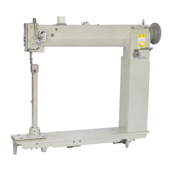
GC24698-25L/-25R Long Arm Post Bed Compound Feed Split Lockstitch Sewing Machine Instruction Manual Parts Catalog SHANGHAI HUIGONG NO.3 SEWING MACHINE FACTORY... -
Page 2: Table Of Contents
----- CONTENTS ----- Preparation for operation ···············································································································1 Safety precautions ·································································································································1 Precaution before Starting Operation ·································································································1 Precaution for Operating Conditions ··································································································1 Cautions on use ·········································································································································1 Lubrication ············································································································································1 Cautions on operation ··························································································································2 Operation ·····················································································································································2 How to attach needle ·····························································································································2 How to wind the lower thread ··············································································································2 Selection of Thread ·····························································································································... -
Page 3: Preparation For Operation
Preparation for operation: 1. Safety precautions: 1) When turning the power on, keep your hands and fingers away from the area around/under the needle and the area around the pulley. 2) Power must be turned off when the machine is not in use, or when the operator leaves the seat. 3) Power must be turned off when tilting the machine head, installing or removing the “V”... -
Page 4: Cautions On Operation
2. Cautions on operation 1) When the power is turned on or off, keep foot away from the pedal. 2) It should be noted that the brake might not work when the power is interrupted or power failure occurs during sewing machine operation. 3) Periodically clean the machine. -
Page 5: How To Route The Upper Thread
4. How to route the upper thread (Fig.7, Fig.8): 1) Pass each upper thread through thread guide A Note: when thin slippery thread (polyester thread for example) is used pass the thread through thread guide B as show in Fig.7 2) With the take-up lever located at the upper most position, pass each thread in the order in Fig.8. -
Page 6: Upper Thread Tension
7、Upper thread tension (Fig.12): 1) The upper thread can be adjusted based on the lower thread tension. 2) Adjustment can be done by rotating the thread tension nut. 8. Adjustment of pressure of presser foot (Fig.13): 1) Pressure should be adjusted according to the material to be sewn. -
Page 7: Walking Foot And Presser Foot Vertical Stroke Adjustment
3) Feed dog height should be measured at the point where the needle is at the top position. For light fabric: Approx 0.8mm For usual fabric: Approx 1.0mm For heavy fabric: Approx 1.2mm Adjustment procedure: 1) Lay down the machine bed toward the other side; 2) Turn the balance wheel by hand stop when the feed dog is raise to its highest position from the surface of needle place;... -
Page 8: Specifications
The force proportionally increases as the mark faces the outside; B. To adjust the force slide the timing belt, loosen the set screw, and turn the eccentric pin; C. After the adjustment, tighten the set screw. Specifications Model GC24698-25R/GC24698-25L Spec Material weight Medium Heavy material Max. sewing speed... -
Page 9: Parts List
A. ARM BED MECHANISM — 7 —... - Page 10 A. ARM BED MECHANISM Fig. Part No. Description Remarks HA300B2090 Rubber plug HA300B2170 Screw SM11/64(40)×9 H4716B8001 Oil guide plate H4717B8001 Thread take-up cover H4715B8001 Rubber plug H4718B8001 Arm side cover (left) H2000B2010 Rubber plug H7117B8001 Arm side cover HA700B2060 Screw SM11/64(40)×8 H2400B2100 Thread guide HA307B0673 Rubber plug...
-
Page 11: Thread Tension Regulator Mechanism
B. THREAD TENSION REGULATOR MECHANISM — 9 —... - Page 12 B. THREAD TENSION REGULATOR MECHANISM Fig. Part No. Description Remarks H2504C6510 Screw 9/64(40)×3 H3221B3142 Tension releasing plate H3221B6812 Tension releasing spring H4705C8001 Screw H4706C8001 Lever HA7311C306 Screw 9/64(40)×7 H4707C8001 Mounting plate H007013050 E-type ring GB/T896 5 H3221B6820 Mounting plate HA300C2030 Screw 11/64(40)×8 H3221B6810 Nut H4708C8001 Spring...
-
Page 13: Arm Shaft Mechanism
C. UPPER SHAFT MECHANISM — 11 —... - Page 14 C. UPPER SHAFT MECHANISM Fig. Part No. Description Remarks HA307C0662 Set screw SM1/4(40)×6 H33111C104 Crank HA105D0662 Set screw SM1/4(40)×4 HA100C2060 Screw SM9/32(28)×13 HA100C2070 Screw SM9/32(28)×14 H4708D8001 Set screw SM1/4(24)×13 H32111B104 Felt H32111B204 Arm shaft bushing (left) H7004D8001 Arm shaft H3205C0661 Spring flange HA113F0684 Screw SM15/64(28)×8.5 H3205C1021 Pulley...
-
Page 15: Presser Foot Mechanism
D. PRESSER FOOT MECHANISM — 13 —... - Page 16 D. PRESSER FOOT MECHANISM Fig. Part No. Description Remarks H4705E8001 Feed lifting rock shaft H4707E8001 Bushing H0030580608 Nut (M6×0.75) H4706E8001 Set screw SM1/4(24)×7 H4709E8001 Crank H3115F0671 Screw SM1/4(28)×16 H2013J0065 Washer H2014J0066 Connecting rod H2000J2100 Screw M6(0.75)×24 H4713E8001 Oil wick H20111C106 Holder H007009250 C-type ring H4714E8001 Eccentric HA307C0662 Screw...
- Page 17 D. PRESSER FOOT MECHANISM Fig. Part No. Description Remarks H4753E8001 Screw SM11/64(40)×17.5 H4708D8001 Set screw SM1/4(24)×13 H7905E8001 Lifting presser H7105E8001 Lifting presser HE204I8001 Finger gusrd — 15 —...
-
Page 18: Thred Take-Up Lever & Needle Bar Mechanism
E. THRED TAKE-UP LEVER & NEEDLE BAR MECHANISM — 16 —... - Page 19 E. THRED TAKE-UP LEVER & NEEDLE BAR MECHANISM Fig. Part No. Description Remarks H24211DN05 Oil wick H4706F8001 Needle bar guide bracket stud H4707F8001 Screw 5/16(28)×10.4 Set screw HA100C2020 15/64(28)×10 Oil wick H24211DN05 Thread take-up lever support stud H24211DM05 Thread take-up lever H3504B0651 Thread take-up slide brock H2405D1112...
- Page 20 E. THRED TAKE-UP LEVER & NEEDLE BAR MECHANISM Fig. Part No. Description Remarks H3129F0693 Thread guide HA100C2170 Screw 1/8(44)×4.5 H3129F0691 Screw 3/32(56)×2.5 H7106F8001 Vibrating presser foot HA700F2100 Screw 11/64(40)×7 — 18 —...
-
Page 21: Stich Regulator Mechanism
F. STICH REGULATOR MECHANISM — 19 —... - Page 22 F. STICH REGULATOR MECHANISM Fig. Part No. Description Remarks H4706G8001 Feed regulator 15/64(28)×8.5 HA113F0684 Screw H3200F2020 Screw 15/64(28)×12 H7104G8001 Link HA100G2070 Eccentric shaft HF30G78001 Reverse stitch shaft HA720F0687 Spring HA700F2030 Stopper pin HF30G58001 Reverse stitch crank HA800F2020 Screw 15/64(28)×13.5 H3207F0672 Screw 11/64(40)×8.5 HA100F2110 Washer H7105G8001 Spring hook...
-
Page 23: Lower And Feeding Shaft Mechanism
G. LOWER AND FEEDING SHAFT MECHANISM — 21 —... - Page 24 G. LOWER AND FEEDING SHAFT MECHANISM Fig. Part No. Description Remarks Lower shaft bushing (left) H4706H8001 Oil wick H4707H8001 Lower shaft H7004H8001 Feed eccentric cam H4710H8001 Screw H3205H0654 SM1/4(40)×5 Lower shaft bushing (right) H4712H8001 Oil wick H4713H8001 Screw H2405D0664 SM15/64(28)×14 Feed eccentric H4717H8001 Needle bearing...
- Page 25 G. LOWER AND FEEDING SHAFT MECHANISM Fig. Part No. Description Remarks H3205G0662 Oil wick H429050050 Bolt GB/T78 M5×5 H7106H8001 Feed bar H3200H2040 Screw SM15/64(28)×17 H2013J0065 Washer H3205H0653 Screw SM1/8(44)×4 H3205H0652 Felt H4743H8001 Feed bar forked connection H007009070 C-type stop ring —...
-
Page 26: Feed Bar Mechanism
H.FEED BAR MECHANISM — 24 —... - Page 27 H.FEED BAR MECHANISM Fig. Part No. Description Remarks H7107I8002 Feed dog H7904I8001 Feed dog H7108I8001 Screw H7104I8001 Feed bar H7105I8001 Square block H7106I8001 Screw H7113I8001 Screw H3208G0675 Nut HA300B2160 Screw 11/64(40)×10 H7109I8001 Cover plate — 25 —...
-
Page 28: Hook Saddle Mechanism
I. HOOK SADDLE MECHANISM — 26 —... - Page 29 I. HOOK SADDLE MECHANISM Fig. Part No. Description Remarks H7124J8001 Screw H7123J8001 Slide plate H7109J8001 Hook saddle H5337D8001 Screw 9/64(36)×30 H2400I2020 Bobbin H7127J7101 Hook H7125J8001 Opener H41622D216 Square block H410270D16 Pin H7115J8001 Cover plate HA105D0662 Screw 1/4(40)×4 H2204C0651 Screw 9/64(40)×6.5 H7106J8001 Collar H7104J8002 Hook shaft H3210F0681 Screw...
-
Page 30: Oil Lubrication Mechanism
J. OIL LUBRICATION MECHANISM — 28 —... - Page 31 J. OIL LUBRICATION MECHANISM Fig. Part No. Description Remarks H32175B304 Felt H4705J7101 Oil pipe complete H3204K0011 Oil reservoir complete H411040160 Screw GB/T819.1 M4×16 H4707J8001 Holder H7005J8001 Felt H7007J7101 Oil pipe complete H32311D606 Holder HA106B0676 Screw SM9/64(40)×4.5 H3200K0170 Holder H3200K0160 Holder H3200K0180 Oil wick Ф2.5×35 H7020J8001 Pressing plate H7021J8001 Sealed cushion...
-
Page 32: Accessories
K. ACCESSORIES (I) — 30 —... - Page 33 K. ACCESSORIES (II) — 31 —...
- Page 34 K. ACCESSORIES Fig. Part No. Description Remarks DP×17-23 JZDP1700P23 Needle DP×17-23 HB01001025 Socket wrench HB01001030 Socket wrench HB01001015 Socket wrench H2400I2020 Bobbin B0-B872(A) HA300J2230 Washer H801045200 Screw GB/T99 4.5×20 H2004O0065 Vibration preventing rubber H2004O0066 Vibration preventing rubber H2404K0654 Hinge complete H2404K0655 Hinge complete H2404K0656 Screw H802080350 Screw...
-
Page 35: Pneumatic Control Unit
L. PNEUMATIC CONTROL UNIT — 33 —... - Page 36 L. PNEUMATIC CONTROL UNIT Fig. Part No. Description Remarks H4915B8001 Air cylinder H4919B8001 Plate HA300B2170 Screw H005008100 Washer H415060200 Screw H4914G8001 Pole H4913G8001 Feeler H4916G8001 Joint H415050450 Screw H0607N8001 Air cylinder H415060200 Screw H005008060 Washer H0605N8001 Plate H0606N8001 Block H4916G8001 Joint H0608N8001 Valve HF106L7101 Touth switch complete —...
- Page 37 SHANGHAI HUIGONG NO.3 SEWING MACHINE FACTORY ADD: 1418, Yishan Road, Shanghai, China Zip Code: 201103 Overseas Business: TEL: 86-21-64853303 FAX: 86-21-64854304 E-mail:highlead@online.sh.cn http://www.highlead.com.cn The description covered in this manual is subject to change for improvement of the commodity without notice 2010.5. Printed...
Need help?
Do you have a question about the GC24698-25L and is the answer not in the manual?
Questions and answers