
Related Manuals for HIGHLEAD HLK-3020


Summary of Contents for HIGHLEAD HLK-3020
-
Page 1: Instruction Manual
HLK-3020 Direct Drive Electronic Bartacking Machine For Soft Cushion Instruction Manual Parts Catalog SHANGHAI BIAOZHUN HAILING SEWING MACHINERY CO., LTD. -
Page 2: For Your Safety
FOR YOUR SAFETY! If you operate the sewing machine first time,please make sure to read the following instructions for your safety and proper operation. CAUTION In this technical manual。the notice is mentioned at some paragraph to attract your attention for the safety.Please keep it in mind whenever you work with the sewing machine. CAUTION is used as the notice to warn a possible danger to cause a wound This technical manual explains the instructions how to operate and maintain the sewing... - Page 3 Caution ★ For avoiding the sewing machine from the troubles,please do not operate the sewing machine under the following conditions. 1. Temperature and humidity During operating: ℃ . The atmosphere temperature should not exceeded more 350 (95°F) or less 5°C(41°F) During transportation:...
-
Page 4: Table Of Contents
------- CONTENTS ----- STRUCTURE OF THE SEWING MACHINE ······························································································· 1 SPECI FICATION··········································································································································· 2 INSTALLATION ············································································································································ 2 3-1. Installation of the control box ····················································································································· 2 3-2. Installation of the power switch ·················································································································· 3 3-3. Installation of the oil pan ···························································································································· 3 3-4. - Page 5 7-7-4 Adjustment of the presser foot standard height ····················································································· 19 7-8. Adjustment of the bobbin winder ·············································································································· 20 7-9. Adjustment of the work holder ·················································································································· 20 7-10. Adjustment of the trimmer cam follower ·································································································· 21 7-11. Adjustment of the position for the movable knife point ············································································· 21 7-12.
-
Page 6: Structure Of The Sewing Machine
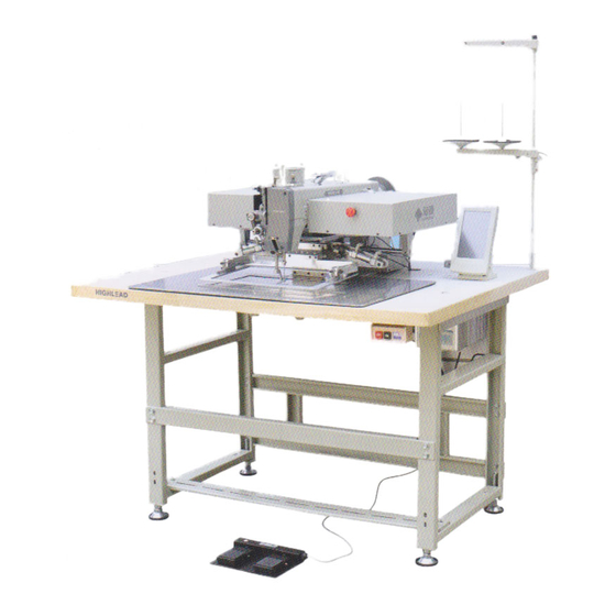
1、STRUCTURE OF THE SEWING MACHINE HLK-3020 electronic pattern sewing machine is constructed with the following main parts ①Sewing machine head ② ③ ④Power supply changer Thread stand Operation Panel ⑤Control Unit ⑥Work holder foot switch ⑦Electromagnetic valve ⑧Wooden Table ⑨Halt switch —... -
Page 7: Speci Fication
2 SPECI FICATION Sewing area: X-Direction(left/right) 150mm Y-Direction(forward/backward) 100mm Maximum sewing speed: 2700 rpm Sewing speed: 10 steps variable from 200 to 2700 rpm Stitch length: 0.1 to 12.7mm Stitch type: Single needle lock stitch Needle bar stroke : 41.2 mm Thread take up lever stroke:... -
Page 8: Installation Of The Control Box
3-1 Installation of the control box If the control box is purchased without assembling to the table, the control box has to be installed underneath the table. Please install the control box with the instruction in the paragraph 3-2 Installation of the power switch If the power switch is purchased without assembling to the table,the power switch has to be attached with the following procedure.... -
Page 9: Installation Of The Oil Pan
3-3 Installation of the oil pan ○ Fix the oil pan 1 at its four corners on the table top with four. 3-4 Installation of the sewing machine head ★ For safety, please use a crane or a crane to install the sewing machine. At the same time to pay attention to table can not move, arm and bed have a stable support. -
Page 10: Installation Of The Spindle Motor
3-5 Installation of the spindle motor If the spindle motor has been removed from the machine for the adjustment or the like, fix the spindle motor as the procedure described right. (1) Spindle motor according to right: put the signal cord upward. (2) Adjust the plane of the motor shaft alignment of the left on the motor mounting holes, 45 °... -
Page 11: Connection Of The Operation Panel
3-6 Connection of the operation panel Please connect the operation panel with the instructions of operation panel manual enclosed in the packing. 3-7 Connection of the electric cables Please make sure to ground the place where there is a mark. Failure to do so may cause electric shock and/or malfunction. -
Page 12: Installation Of The Thread Stand
3-8 Installation of the thread stand (1) Assemble the thread stand with the instructions enclosed in the packing. ○ (2) Fit the thread stand 1 in the thread stand holeg on the tabletop. ○ ○ (3) Fix the thread stand 1 firmly from the rear side of the table with tightening the nut 4 and the ○... -
Page 13: Proper Operation
5 PROPER OPERATION 5-1 Installation of the needle Caution ★Please make sure to turn the power switch OFF before installing or replacing the needle. ★Please pay attention for the fingers not to be wounded by the needlepoint. ○ (1) Loosen the needle set screw 1 then,... -
Page 14: Winding The Bobbin Thread
5-3 Winding the bobbin thread ★Please make sure to pull the upper thread out of the needle before winding the bobbin thread (1) Turn the power switch ON. (2) Pass through the thread from the thread stand①as shown on the right figure . then,wind the thread to the empty bobbin②in the arrow mark “a”... -
Page 15: Setting The Bobbin Case
5-5 Setting the bobbin case (1) Set the needle bar to its highest position then,open the cylinder cover①. (2) Open the bobbin case latch lever②fully then, fit it securely in the inner hook③. [NOTE]Please pull the bobbin thread about 2.5mm out of the thread hole(NO.4)of the bobbin case.... -
Page 16: Adjustment Of The Thread Tension
★ Please make sure to always operate the sewing machine with the safety guards. ★ Please do not put unnecessary articles except for the sewing operation on the tabletop. ★ Please keep the hands and the face away from the needle. (1) Turn the power switch①ON. -
Page 17: Standard Adjustment
(2) Upper thread tension Adjust the upper thread tension based on the bobbin thread tension.For this adjustment,turn the thread tension adjusting nut③④.The upper tread tension becomes tight if turn the thread tension adjusting nut③ ④to the clockwise,and the upper thread tension becomes loose if turns it to the counter clock wise. 7 STANDARD ADJUSTMENT Caution ★... -
Page 18: Adjustment Of The Position Between The Needle And The Shuttle Hook
7-2 Adjustment of the position between the needle and the shuttle hook (1) Turn the power switch OFF. (2) Turn the sewing machine pulley by hand then,move up the needle bar① from the lowest position and stop it at the position②where the needle bar timing mark C is matched to the needle bar bushing bottom line.... -
Page 19: Adjustment Of The Clearance Between The Shuttle Hook And The Needle
7-4 Adjustment of the clearance between the driver and the needle (1) Please take same procedures above paragraph 7-2.from(1)to(5). (2) Please make sure clearance between the shuttle hook point and the needle has been adjusted 0.05~0.1 mm above procedure Adjustment of the clearance between the shuttle hook and the needle.... -
Page 20: Adjustment Of The Wiper
7-6 Adjustment of the wiper (1) Loosen the wiper setscrew③and adjust the wiper①to be positioned where the wiper①passes under the needle point②with about 2 mm clearances right after the sewing machine is stopped running at the needle upper position (the thread take up lever's highest position). [NOTE] When the presser foot position or the presser foot lift is changed, the wiper①may collide with the presser foot④.in that case, please do not use the wiper○... - Page 21 ⑪ (5) Insert the sewing material⑩under the work holder and turn the sewing machine pulley by hand ⑫ then,stop the presser foot at the lowest position. ⑭ ⑫ (6) Loosen the presser foot bar setscrew and move the presser foot bar⑦then,adjust the presser foo ⑫...
-
Page 22: Adjustment Of The Presser Foot Lift During The Sewing
7-7.2 Adjustment of the presser foot lift during the sewing [NOTE]The presser foot lift during the sewing can be adjusted 0 and 2~10mm. (1) The presser foot lift during the sewing becomes 4~10mm at the condition which the connection of the link②and the lever③with the shoulder screw①is as shown on the figure and it becomes 2 to 4 mm if the connection is made with A hole,and it becomes 0 mm if the connection is made with B hole.... -
Page 23: Adjustment Of The Presser Foot Timing
7-7.3 Adjustment of the presser foot timing [NOTE] The presser foot up and down movement during the sewing synchronizes with the needle up and down movement. With changing this synchronized timing to the sewing materials,the skip stitches can be prevented or the seam tightness can be improved. For example,the delay of the presser foot timing against the needle movement prevents the skip stitches especially to the thin materials,and the advance of the presser foot timing can improve the seam tightness especially to the thick materials.... -
Page 24: Adjustment Of The Presser Foot Standard Height
7-7.4 Adjustment of the presser foot standard height Note: the standard height of the presser foot is 20 mm. (1) 、Open the head panel , the attachment block ① into the needle on the surface, presser foot ② down to the gauge①, height of 20mm. (2)... -
Page 25: Adjustment Of The Bobbin Winder
7-8 Adjustment of the bobbin winder (7) Adjustment of the winding volume Loosen the setscrew②of the adjusting lever①and adjust the position of the adjusting lever①.If move the adjusting lever①to the arrow direction “a” the Winding volume is reduced,and if move the adjusting lever①to the arrow direction “b”,... -
Page 26: Adjustment Of The Trimmer Cam Follower
7-10 Adjustment of the trimmer cam follower (1) Turn the power switch OFF and remove the top cover. (2) Under the sewing machine regular stop condition(the needle stop position is upper and the take up lever stop position is highest),loosen the setscrew⑤of the cam follower lever ④and adjust the cam follower②to be positioned to contact with the shoulder portion③of the trimmer cam①with having about 1 mm clearance between the cam follower②and the trimmer cam①.After this adjustment,... -
Page 27: Adjustment Of The Fixed Knife Position
7-12 Adjustment of the fixed knife position (1) Open the cylinder cover①. (2) Remove the E-shaped snap ring④,which engages the movable knife②and the link③. (3) Loosen the setscrews⑤then, remove the sliding plate⑥. (4) Turn the sliding plate ⑥ upside down and loosen two setscrews⑨then,adjust the fixed knife ⑩... -
Page 28: Cancellation Of The Trimming Function
7-16 Cancellation of the trimming function If the automatic trimming is not required during the sewing operation ,cancel the Trimming function with the setting panel of the control box . 7-17 Adjustment of the upper thread tension release [NOTE] (a) The upper thread tension release works when the upper thread is trimmed automatically or the presser foot is lifted during the work holder feeding. - Page 29 (1) Turn the power switch cancel sewing area limit with the operation panel. (2) After the cancellation of the sewing area limit, once. Turn the power switch OFF. 7-18.1 Shifting the mechanical home position to the X direction (1) Remove cover (right),(left) and X cover.
-
Page 30: Maintenance
8 MAINTENANCE Caution ★Please make sure to turn the power switch always OFF when clean up the sewing machine. ★Before or after the sewing operation,clean up the sewing machine and check the Oil level in the oil tank. 8-1 Cleaning (1) Turn the power switch OFF.... -
Page 31: Bad Sewing Condition&Its Cause And Rem Edy
9 BAD SEWING CONDITION&ITS CAUSE AND REM EDY [NOTE]Please fix the troubles during the sewing machine operation with referring to the following instructions.Beside,if the trouble conditions are not coming under these classification,please contact the sewing machine dealers nearby. Cause Remedy Ref. - Page 32 Cause Remedy Ref. page & condition item Too short bobbin thread by Use non racing spring with bobbin — bobbin spinning after trimming Bobbin thread tension is too Loosen bobbin thread tension spring tight Thread tail from needle is Decrease pre-tension 7-16 Skip stitch very short after trimming...
- Page 33 Cause Remedy Ref.page & condition item Upper thread tension is not Increase upper thread tension tight enough Adjust tension regulator position 7-17 Thread tension regulator’s properly discs are opened during Adjust upper tension release position 7-17 sewing properly Stitch forming Presser foot position is not Adjust presser foot position properly is loose...
- Page 34 Cause Remedy Ref. page & item condition X-Y detectors cable are Connect X-Y cables precisely — disconnected X-Y detectors cable are Change them new detectors — Work holder out of order does no stop at Detector detector Adjust the clearance properly 7-19 home position plate clearance is too big...
-
Page 35: Arm Bed &It's Accessories(一
A.ARM BED &IT'S ACCESSORIES(一) — 29 — — 29 —... - Page 36 A.ARM BED &IT'S ACCESSORIES(一) 序号 样本编号 名 称 数量 备 注 A01 HN71B48001 Type plate A02 H924025050 A03 H6697F8001 Screw M4×8 A04 HN71B58001 X motor cover A05 HN73B28001 Motor cover A06 HN73B38001 Motor shelf A07 H6692D8001 Screw M5×12 A08 HN71B68001 Y Motor cover A09 HN71B88001 Rear cover (left)
- Page 37 A.ARM BED &IT'S ACCESSORIES(一) 序号 样本编号 名 称 数量 备 注 A44 H6623C8001 Screw M4×8 A45 HN71G88001 Gasket A46 HN71G78001 Bracket A47 H415060120 Screw M6×12 A48 H005001060 Washer A49 HN71G58001 Bracket A50 HN71G68001 Bracket A51 H003002040 A52 H005001040 Washer A53 HN71G38001 Rubber washer A54 H416040120 Screw...
-
Page 38: Arm Bed &It's Accessories(二
B.ARM BED &IT'S ACCESSORIES(二) — 32 — — 32 —... - Page 39 B.ARM BED &IT'S ACCESSORIES(二) 序号 样本编号 名 称 数量 备 注 B01 HN74B07101 Reel wire implement B02 H3200B2100 Screw 9/64(40)×6.5 B03 HA17901-61 Full wire plate B04 H6720N8001 Lever B05 HA100H2150 Screw 9/64(40)×11 B06 H007013050 E-type retaining ring B07 H6722N8001 Washer Φ12×Φ6×3 B08 HA17901-64 shaft...
- Page 40 B.ARM BED &IT'S ACCESSORIES(二) 序号 样本编号 名 称 数量 备 注 B44 HA17902-72 Thread tension spring B45 H660GB8001 Thumb nut B46 HN71C67101 Needle cooler seat B47 HN71C78001 Oil gauge B48 H6692B8001 Screw 9/64(40)×3.2 B49 HN71C58001 Thread guide B50 HN71C48001 Felt Φ8×15.5 B51 HN71C38001 Needle cooler seat...
- Page 41 B.ARM BED &IT'S ACCESSORIES(二) 序号 样本编号 名 称 数量 备 注 B87 H415030080 Screw M3×10 — 35 —...
-
Page 42: Sewing Mechanism(一
C.SEWING MECHANISM (一) — 36 — — 36 —... - Page 43 C.SEWING MECHANISM(一) 序号 样本编号 名 称 数量 备 注 C01 HA17901-16 Bearing module C02 H3208H0661 Bearing B6004ZZNR D42/d20/B12 C03 H8812D8001 Bearing B6004ZZ D42/d20/B12 C04 HA17901-17 Bushing C05 H431060080 Screw M6×8 C06 HA17905-02 connecting rod C07 H6608C8001 Pulley C08 H431040060 Screw M4×6 C09 HA307C0662 Screw...
- Page 44 C.SEWING MECHANISM(一) 序号 样本编号 名 称 数量 备 注 C44 HA100C2070 Screw 9/32(28)×10 C45 HA17902-15 Shaft module C46 H431050080 Screw M5×8 C47 HA100C2200 Square block C48 H6623C8001 Screw M4×8 C49 H6622C8001 Slide block guide C50 H5311F8001 Screw 11/64(40)×6.1 C51 HK42C98001 Hand wheel C52 HA15401-15 Shaft...
-
Page 45: Sewing Mechanism(二
D.SEWING MECHANISM (二) — 39 — — 39 —... - Page 46 D.SEWING MECHANISM(二) 序号 样本编号 名 称 数量 备 注 D01 HA17902-33 Connecting rod assy D02 H6676E8001 Screw M5×14 D03 HA17902-48 Bearing D04 HA17901-37 Bushing D05 H431050080 Screw M5×8 D06 H2010J0066 9/32(28) D07 H6631C8001 Sector gear D08 H431050060 Screw M5×6 D09 HA17902-38 Screw 9/32×28 D10 HA17902-39...
- Page 47 D.SEWING MECHANISM(二) 序号 样本编号 名 称 数量 备 注 D44 H431060120 Screw M6×12 — 41 —...
-
Page 48: X-Y Table Mechanism(一
E.X-Y TABLE MECHANISM (一) — 42 — — 42 —... - Page 49 E.X-Y TABLE MECHANISM(一) 序号 样本编号 名 称 数量 备 注 E01 HN73D57101 X slide guide SHW12HRM E02 H415040080 Screw M4×8 E03 HN76D08001 Detector X mounting plate E04 H6696F8001 Screw M4×10 E05 HN74D68001 Belt clamper E06 H415030060 Screw M3×6 E07 HN73D68001 Movable race X E08 H6696F8001 Screw...
-
Page 50: X-Y Table Mechanism(二
F.X-Y TABLE MECHANISM (二) — 44 — — 44 —... - Page 51 F.X-Y TABLE MECHANISM(二) 序号 样本编号 名 称 数量 备 注 F01 HN72D68001 Motor X F02 H415050160 Screw M5×16 F03 HN72D18001 Gear X(small) m=1,z=24 F04 H431060060 Screw M6×6 F05 HN72D28001 Bearing B6201ZZNR(D32/d12/B10) F06 HN72D38001 Motor bracket X F07 HS90329130 Screw M6×30 F08 H005001060 Washer F09 H007013120...
- Page 52 F.X-Y TABLE MECHANISM(二) 序号 样本编号 名 称 数量 备 注 F44 HN71D08001 retaining ring F45 HS90329130 Screw M6×30 F46 H005001060 Washer F47 HN70D68001 Bracket F48 H104060550 Bolt M6×55 F49 H431050080 Screw M5×8 — 46 —...
-
Page 53: X-Y Table Mechanism(三
G.X-Y TABLE MECHANISM (三) — 47 — — 47 —... - Page 54 G.X-Y TABLE MECHANISM(三) 序号 样本编号 名 称 数量 备 注 G01 H415030050 Screw M3×5 G02 HN75D78001 Shutter guide G03 H415040080 Screw M4×8 G04 HN75D88001 Plate G05 HN75D58001 Shutter G06 H6684E8001 Screw M5×8 G07 HN75D68001 Shutter setting plate G08 HN75D37101 Movable cover G09 HN75D27101 Movable cover G10 HN75D17101...
-
Page 55: Work Holder Mechanism
H.WORK HOLDER MECHANISM(AIR OPERATED) — 49 — — 49 —... - Page 56 H.WORK HOLDER MECHANISM(AIR OPERATED) 序号 样本编号 名 称 数量 备 注 H01 H007013060 E-type retaining ring H02 H005001080 Washer H03 HN71E38001 Axle H04 HN71E18001 Pressure lever H05 H431060060 Screw M6×6 H06 H6637E8001 Screw M4×8 H07 H007013050 E-type retaining ring H08 HN71E88001 H09 HN71E78001 Cylinder joint H10 HN71E28001...
- Page 57 H.WORK HOLDER MECHANISM(AIR OPERATED) 序号 样本编号 名 称 数量 备 注 H44 HBI3277081 Axle H45 HBI3275081 H46 H003002050 H47 H426050180 Screw M5×18 H48 HBI3274081 Connect pedestal H49 H415040080 Screw M4×8 H50 HN73E27101 Work clamp assy H51 HN73E18001 Feed plate H52 H6684E8001 Screw M5×8 H53 H605020090...
-
Page 58: Presser Foot Mechanism(一
I.PRESSER FOOT MECHANISM(一) — 52 — — 52 —... - Page 59 I.PRESSER FOOT MECHANISM(一) 序号 样本编号 名 称 数量 备 注 I01 HN70F98001 Stepping motor I02 H415040140 Screw M4×14 I03 H431050060 Screw M5×6 I04 HA17905-37 Gear I05 HN71F08001 Detector plate spacer I06 HN71F58001 Detector plate I07 H6685D8001 Washer I08 H415040050 Screw M4×5 I09 HN70F68001 Motor bracket...
-
Page 60: Presser Foot Mechanism(二
J.PRESSER FOOT MECHANISM(二) — 54 — — 54 —... - Page 61 J.PRESSER FOOT MECHANISM(二) 序号 样本编号 名 称 数量 备 注 J01 HA309H0681 Screw 1/2(28)×49 J02 HA117H0692 1/2(28) J03 HM025F8001 Presser bar guide J04 H662IB8001 Spacer J05 HM026F8001 Presser spring J06 H6027H8001 Presser bar holder J07 HA3411D308 Screw 15/64(28)×6 J08 70018 O ring 7×1.8-A J09 HM029F8001...
- Page 62 J.PRESSER FOOT MECHANISM(二) 序号 样本编号 名 称 数量 备 注 J44 H20111C106 Holder J45 HA17905-10 Felt H 2mm L 66mm J46 HA17905-09 Felt holder — 56 —...
-
Page 63: Thread Trimming Mechanism
K.THREAD TRIMMING MECHANISM — 57 — — 57 —... - Page 64 K.THREAD TRIMMING MECHANISM 序号 样本编号 名 称 数量 备 注 K01 H6623C8001 Screw M4×8 K02 H6675F8001 Screw 3/32(56)×2.8 K03 H6676F8001 needle plate K04 H6677F8001 Spacer K05 H6681F8001 Slide plate K06 H6695F8001 Spacer K07 H6673F8001 Fixed knife K08 H6692B8001 Screw 9/64(40)×3.2 K09 H6680F8001 Spring K10 H6671F8001...
- Page 65 K.THREAD TRIMMING MECHANISM 序号 样本编号 名 称 数量 备 注 K44 H003001060 K45 HA17906-11 Holder plate K46 H416050120 Screw M5×12 K47 HDG4068001 Crank K48 H6683D8001 K49 H6613F8001 Spring washer K50 H6685D8001 Washer K51 HA17906-04 mounting plate K52 HN71G97101 Solenoid assy —...
-
Page 66: Wiper Mechanism
L.WIPER MECHANISM — 60 — — 60 —... - Page 67 L.WIPER MECHANISM 序号 样本编号 名 称 数量 备 注 L01 HN71H38001 Cover L02 H6642B8001 Screw M4×8 L03 HN70H97101 Solenoid assy L04 HA708P0669 Screw M3×5 L05 HN72H28001 Rubber washer Φ18/Φ12.5/4 L06 H005001060 Washer L07 HA17907-10 Spacer L08 HA17907-13 Spring L09 HA17907-11 Spacer L10 HN71H08001 Stopper...
- Page 68 L.WIPER MECHANISM 序号 样本编号 名 称 数量 备 注 L44 HK40H68001 Cover L45 H6682D8001 Screw M4×10 L46 HK40H78001 setting plate — 62 —...
-
Page 69: Oil Lubrication Mechanism
M.OIL LUBRICATION MECHANISM — 63 — — 63 —... - Page 70 M.OIL LUBRICATION MECHANISM 序号 样本编号 名 称 数量 备 注 M01 HM008I8001 Felt holder M02 H6642B8001 Screw M4×8 M03 HA17908-06 Felt holder M04 H3200G2030 Felt holder M05 HA300I2060 Holder M06 HN71I87101 Felt M07 HN70I67101 Oil pipe assy M08 HN70I97101 Oil pipe assy M09 HA300B2110 Rubber plug M10 HA17908-38...
-
Page 71: Cable Component & Detector Mechanism
N.CABLE COMPONENT & DETECTOR MECHANISM — 65 — — 65 —... - Page 72 N.CABLE COMPONENT & DETECTOR MECHANISM 序号 样本编号 名 称 数量 备 注 N01 HN70J78001 Print circuit board N02 H6609I8001 Screw M4×20 N03 H6607I8001 Nylon bush N04 H6608I8001 Nylon bush N05 HN70J88001 Bracket N06 H6692D8001 Screw M5×12 N07 HN70J98001 Connector panel N08 H6697F8001 Screw M4×8...
-
Page 73: Accessories(一
O.ACCESSORIES(一) — 67 — — 67 —... - Page 74 O.ACCESSORIES(一) 序号 样本编号 名 称 数量 备 注 O01 HN72K47101 Leg assy O02 H802035190 Screw 10 3.5×19 O03 HN73K38001 Rail O04 HN73K28001 Drawer O05 H003001080 O06 H005008080 Spring washer O07 GB/T 96.1 8 Washer O08 HN72K18001 Table top O09 H125080700 Bolt M8×75 O10 HN71K08001...
-
Page 75: Accessories(二
P.ACCESSORIES(二) — 69 — — 69 —... - Page 76 P.附件(二) 序号 样本编号 名 称 数量 备 注 P01 JZDP1700G1801 Needle P02 H6685C8001 Bobbin P03 HA200J2030 Cotton stand assy P04 HM007K7101 Thread guide peculiar order P05 HB00001060 Hexagonal wrench 6 P06 HB00001050 Hexagonal wrench 5 P07 HB00001040 Hexagonal wrench 4 P08 HB00001030 Hexagonal wrench 3 P09 H6618J8001...
- Page 77 SHANGHAI BIAOZHUN HAILING SEWING MACHINERY CO., LTD. ADD: NO.850 Shulin Road, Songjiang District Shanghai, P.R.China Zip Code: 201612 Overseas Business: TEL: 86-21-64853303 FAX: 86-21-64854304 E-mail:sales@highlead.com.cn http://www.highlead.com.cn The description covered in this manual is subject to change for improvement of the commodity without notice 2018.5. Printed...
Need help?
Do you have a question about the HLK-3020 and is the answer not in the manual?
Questions and answers