Table of Contents
Advertisement
Quick Links
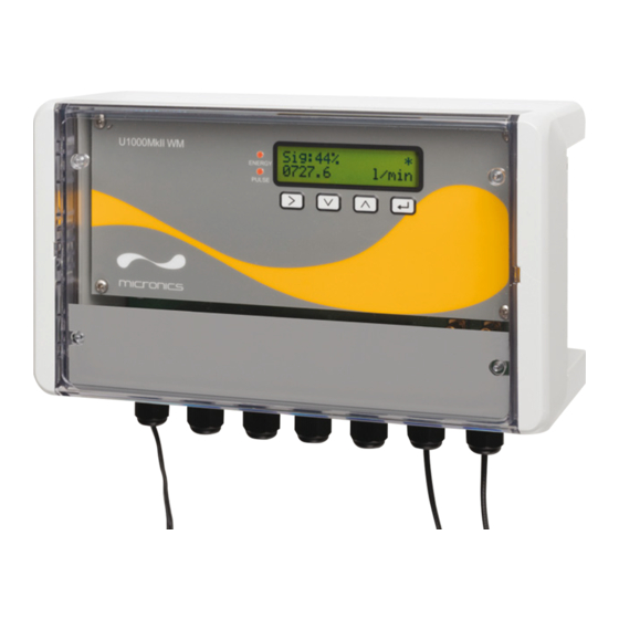
U1000MkII WM
U1000MKII-WM:Wall-Mounted Ultrasonic Flow Meter
Wall-Mounted Ultrasonic Heat Meter
User Manual
Micronics Ltd, Knaves Beech Business Centre,
Davies Way, Loudwater, High Wycombe, Bucks HP10 9QR
Telephone: +44(0)1628 810456
E-mail:
sales@micronicsltd.co.uk
www.micronicsflowmeters.com
Issue 1.0
Advertisement
Table of Contents

Related Manuals for Micronics U1000MkII WM


Summary of Contents for Micronics U1000MkII WM
- Page 1 U1000MkII WM U1000MKII-WM:Wall-Mounted Ultrasonic Flow Meter Wall-Mounted Ultrasonic Heat Meter User Manual Micronics Ltd, Knaves Beech Business Centre, Davies Way, Loudwater, High Wycombe, Bucks HP10 9QR Telephone: +44(0)1628 810456 E-mail: sales@micronicsltd.co.uk www.micronicsflowmeters.com Issue 1.0...
-
Page 3: Table Of Contents
Current Output (if fitted) ....................9 2.2.6 Modbus/MBUS Connections (if fitted) ................ 10 Switch On ......................... 12 2.3.1 U1000MkII WM Flow Meter ..................12 2.3.2 U1000MkII WM Heat Meter ..................13 Assemble the Guiderail ..................... 14 Adjust Flow Sensor Separation ..................14 Apply Gel Pads ......................... - Page 4 U1000MKII WM User Manual Micronics 3.6.1 Volume Pulse ......................22 3.6.2 Flow Alarm ........................ 22 3.6.3 Energy Pulse (Heat Meter versions only) ..............23 3.6.4 Frequency ......................... 23 Calibration Menu ......................24 Volume Totals Menu ......................24 Diagnostics Menu ......................25 4 OUTPUTS ............................
-
Page 5: Introduction
U1000MKII WM User Manual INTRODUCTION General Description This manual describes the installation and use of the two models in the U1000MkII WM range: • U1000MkII WM Flow Meter is a wall-mounted control unit with a clamp-on ultrasonic flow sensors for measuring flow rate and total flow with a volume pulse output. It can be used as a standalone meter or as part of an integral management system. -
Page 6: How Does It Work
U1000MKII WM User Manual Micronics How Does It Work? The U1000MKII WM uses a cross correlation transit time algorithm to provide accurate flow measurements. An ultrasonic beam of a given frequency is generated by applying a repetitive voltage pulse to the transducer crystals. -
Page 7: Package Contents
Micronics U1000MKII WM User Manual Package Contents The unit consists of: Wall-mounted electronics and control unit Consisting of the keypad and display, power, signal and Modbus connections and cabling. Ultrasonic Flow Sensors Two transducers for flow measurement with VHB gel pads to ensure good contact with pipework. - Page 8 U1000MKII WM User Manual Micronics Figure 2 Package Contents Page 4 Issue 1.0 Nov 2020...
-
Page 9: Display
Select menu or exit to Flow Reading screen. Figure 3 U1000MKII WM display (Heat Meter model shown) Issue 1.0 Nov 2020 Page 5... -
Page 10: Quick Start Procedure
Micronics Quick Start Procedure The following procedure summarises the steps required to set up the U1000MkII WM. Please refer to the referenced sections for full details. Identify a suitable location for the sensors and guide rail on a straight length of pipe clear of bends and valves or similar obstructions (See pages 7 and 41). -
Page 11: Installation
IMPORTANT: DO NOT EXPECT TO OBTAIN ACCURATE RESULTS IF THE UNIT IS POSITIONED CLOSE TO ANY OBSTRUCTION THAT DISTORTS THE UNIFORMITY OF THE FLUID FLOW PROFILE (SEE PAGE 41). MICRONICS LTD ACCEPTS NO RESPONSIBILITY OR LIABILITY IF PRODUCT HAS NOT BEEN INSTALLED IN ACCORDANCE WITH THESE INSTRUCTIONS. -
Page 12: Clean The Pipe's Flow Sensor Contact Area
2.2.1 Power Supply The U1000MKII WM will operate within the voltage range 12 - 24V AC/DC. Micronics can supply, as an optional item, a 12VAC power supply. If you intend to use an alternative power supply it must have a minimum rating of 7VA per instrument. Connect the power supply to the left-hand terminal block labelled +VIN, -VIN and Screen. -
Page 13: Pt100 Sensors (Heat Meter Versions Only)
2.2.5 Current Output (if fitted) U1000MkII WM unit can be optionally configured with a 4-20mA output. The isolated 4-20mA is a current source and can drive into a maximum load of 620Ω. If fitted, the 4-20mA current outputs are available at the terminal block labelled IO0 4-20mA with RET and OUT connections. -
Page 14: Modbus/Mbus Connections (If Fitted)
U1000MKII WM User Manual Micronics 2.2.6 Modbus/MBUS Connections (if fitted) If fitted, the Modbus or MBUS output is available at the terminal blocks labelled IO1 1/01-04 terminals: IO1 Terminal Modbus MBUS ISOL_GND ISOL_GND OUT_A BUS1_IN ISOL_GND ISOL_GND OUT_B BUS2_IN For reliable operation of a Modbus network the cable type and installation must comply with requirements in the Modbus specification document: “MODBUS over Serial Line Specification &... - Page 15 Micronics U1000MKII WM User Manual Figure 9 Modbus wiring without spurs Figure 10 M-Bus wiring with spurs Figure 11 M-Bus wiring without spurs Issue 1.0 Nov 2020 Page 11...
-
Page 16: Switch On
The initial screen sequence is different for the Flow Meter and Heat Meter models. 2.3.1 U1000MkII WM Flow Meter Switch on the power to the Electronics Module. A Micronics start-up screen is displayed for 5 seconds followed by hardware and software version information. Select the pipe material by using the... -
Page 17: U1000Mkii Wm Heat Meter
Continue with the installation of the Sensor Assembly (see page 14). 2.3.2 U1000MkII WM Heat Meter Switch on the power to the Electronics Module. A Micronics start-up screen is displayed for 5 seconds followed by hardware and software version information. Select the pipe material by using the... -
Page 18: Assemble The Guiderail
U1000MKII WM User Manual Micronics Select the Instrument Type using Instrument Type: The unit is preconfigured for Heating applications. Heating|Chiller Press to confirm the setting. Select the Instrument Side (where flow sensors are Instrument Side: installed) using Return|Flow The unit is preconfigured for Flow. -
Page 19: Calibrate The Pt100 Sensors (Heat Meter Versions Only)
Micronics U1000MKII WM User Manual when the unit is mounted at this angle (see page 41). This minimises the effect of any flow turbulence resulting from entrained air along the top of the pipe and sludge at the bottom. Calibrate the PT100 Sensors (Heat Meter versions only) IMPORTANT: THE PT100 SENSORS MUST BE BALANCED BEFORE INITIAL USE, USING THE PROCEDURE DESCRIBED BELOW AND USED WITH THE CABLE LENGTH SUPPLIED. -
Page 20: 2.10 Normal Operation
U1000MKII WM User Manual Micronics 2.10 Normal Operation The screen sequence is different for the Flow Meter and Heat Meter models. 2.10.1 U1000MkII-WM Flow Meter Press The unit checks for a valid flow signal. Checking Signals Searching... If a valid signal is found, signal strength and flow rate Sig:80% are displayed. -
Page 21: Troubleshooting The Flow Reading
Micronics U1000MKII WM User Manual 2.10.3 Troubleshooting the Flow Reading The direction of flow when powered up will be taken to be the positive flow direction. The pulse output will relate to the flow in this direction. If the flow is reversed then the flow rate will still be displayed but the activity indication will change from an asterisk to an exclamation mark and no pulses will be generated. -
Page 22: Menus
U1000MKII WM User Manual Micronics MENUS The password-protected menus allow you to change the default settings: • Setup (see page 19) • Current Output (see page 20) – if 4-20mA output option installed • Modbus (see page 21) – if Modbus output option installed •... -
Page 23: Setup Menu
Micronics U1000MKII WM User Manual Setup Menu Choose whether to use imperial or metric units (default). If “inches” option is selected, the temperatures will be Select Dims: mm|inches displayed in °F and the energy values will be in BTUs. The following diagrams show the metric options only. -
Page 24: Current Output Menu (4-20Ma Versions Only)
U1000MKII WM User Manual Micronics Heat Meters only Instrument Side: Select the Instrument Side (where flow sensors are Return|Flow installed) using The unit is preconfigured for Flow. Press to confirm the setting. Select the fluid using Instrument Fluid Glycol|Water Press to confirm the fluid name. -
Page 25: Modbus Setup Menu (Modbus Versions Only)
Micronics U1000MKII WM User Manual Modbus Setup Menu (Modbus versions only) Enter the Modbus Address for this unit. The valid range is Modbus Address: 1 to 126. Press to confirm the setting. Enter the baud rate for the Modbus network. Valid Modbus Baud: settings are 1200, 2400, 4800, 9600, 19200, or 38400. -
Page 26: Pulse Output Menu
U1000MKII WM User Manual Micronics Pulse Output Menu All models allow the use of a pulse output based on Volume pulse, Alarm, Energy pulse (Heat Meter versions only) or Frequency indicating flow rate. Enable or disable the Pulse output using... -
Page 27: Energy Pulse (Heat Meter Versions Only)
Micronics U1000MKII WM User Manual 3.6.3 Energy Pulse (Heat Meter versions only) Choose from 1,10,100kWh or 1MWh when in metric mode Energy Pulse: and 1,10,100kBTU or 1MBTU in imperial mode. Each 1 k/Wh pulse represents the selected amount of energy e.g. -
Page 28: Calibration Menu
U1000MKII WM User Manual Micronics Calibration Menu Choose a Damping Time of 10, 20, 30, 50 or 100s. Damping Time[s]: Press to confirm the setting. Set the Zero Cut-Off value (in the range 0.00 – 0.50 m/s). Zero Cut-Off: Press to confirm the setting. -
Page 29: Diagnostics Menu
Micronics U1000MKII WM User Manual Diagnostics Menu The diagnostics menu provides some additional information about the flowmeter and its setup. The menu can be accessed by pressing the key from the main flow-reading screen. Press the keys to move between the diagnostics screens. -
Page 30: Outputs
4.1.1 Volumetric Pulse The U1000MKII WM default pulse width is set to 50ms which represents half of one pulse cycle. A 50ms pulse width is required for most mechanical counters. Formula to obtain Volume per Pulse based on a (default) 50ms pulse width: Volume per Pulse >= maximum flow rate (in litres per minute) / 600... -
Page 31: Frequency Mode
Micronics U1000MKII WM User Manual 4.1.2 Frequency Mode In Frequency mode, the output frequency is proportional to the flow rate within a specified frequency range of 1 – 200Hz. The flow units are fixed as litres per second. 4.1.3 Energy Pulse (Heat Meter versions only) When the Pulse Output is set to Energy, the kWh LED will be permanently illuminated. -
Page 32: Modbus (If Fitted)
U1000MKII WM User Manual Micronics Modbus (if fitted) The Modbus RTU interface is configured via the Modbus sub menu. • Float byte order –AB CD – Big endian – MSB first. • The data rate can be selected in the range 1200 to 38400 baud. - Page 33 Micronics U1000MKII WM User Manual The following registers are available. Modbus Register Typical Type Meaning Notes Register Offset Contents Byte 0x01 Instrument Address Byte 0x03 Instrument Command Number of bytes to Byte 0x40 read 0x00 40001 Int-16 Device ID 0xAC...
- Page 34 U1000MKII WM User Manual Micronics (continued) Modbus Register Typical Type Meaning Notes Register Offset Contents 0x41 Units in Degrees 40015 Celsius for Metric 0x98 IEEE754 Measured Temperature (Hot) Units in Degrees float (Heat Meter versions only) 0x00 Fahrenheit for 40016...
-
Page 35: M-Bus (If Fitted)
Micronics U1000MKII WM User Manual M-Bus (if fitted) After power-up, the unit defaults to the baud rate and primary address set in the M-bus Menu (see page 21). Both the baud rate and primary address may be changed later over the M-Bus network. -
Page 36: Select Slave Function
U1000MKII WM User Manual Micronics 4.4.2 Select Slave Function COMMAND: SEND_NKE DESCRIPTION: Initialise / Reset slave device for communications. DIRECTION: MASTER TO SLAVE FRAME TYPE: SHORT / LONG FRAME PRIMARY ADDRESSING SECONDARY ADDRESSING NAME CODE NAME CODE START 0x10 START... -
Page 37: Req_Ud2 - Request Data
Micronics U1000MKII WM User Manual 4.4.4 REQ_UD2 – REQUEST DATA REQ_UD2 – REQUEST DATA COMMAND: DESCRIPTION: DIRECTION: MASTER TO SLAVE FRAME TYPE: CONTROL / LONG FRAME PRIMARY ADDRESSING SECONDARY ADDRESSING NAME CODE NAME CODE START 0x68 START 0x68 LENGTH 0x04... -
Page 38: 4.4.5 Rsp_Ud2 - Return Data
U1000MKII WM User Manual Micronics 4.4.5 RSP_UD2 – RETURN DATA RSP_UD2 – RETURN DATA COMMAND: DESCRIPTION: DIRECTION: SLAVE TO MASTER FRAME TYPE: LONG FRAME NAME DESCRIPTION SIZE CODE START 0x68 LENGTH 0xXX LENGTH 0xXX START 0x68 (C - FIELD) RSP_UD... -
Page 39: Switch Baud Rate Function
Micronics U1000MKII WM User Manual 4.4.6 Switch Baud Rate Function SEND_UD – SET BAUD RATE 300 SEND_UD – SET BAUD RATE 300 COMMAND: DESCRIPTION: Sets the slave data rate to 300 baud. The slave responds to the request with ACK at the current baud and then modifies its baud setting. - Page 40 U1000MKII WM User Manual Micronics SEND_UD – SET BAUD RATE 2400 SEND_UD – SET BAUD RATE 2400 COMMAND: DESCRIPTION: Sets the slave data rate to 2400 baud. The slave responds to the request with ACK at the current baud and then modifies its baud setting.
- Page 41 Micronics U1000MKII WM User Manual SEND_UD – SET BAUD RATE 9600 SEND_UD – SET BAUD RATE 9600 COMMAND: DESCRIPTION: Sets the slave data rate to 9600 baud. The slave responds to the request with ACK at the current baud and then modifies its baud setting.
-
Page 42: Change Primary Address Function
U1000MKII WM User Manual Micronics 4.4.7 Change Primary Address Function SEND_UD – SET PRIMARY ADDRESS COMMAND: DESCRIPTION: The primary address of the slave is set to a default value at power up. The master uses this command to assign a new unique primary address to the slave if required. -
Page 43: Appendix
Micronics U1000MKII WM User Manual APPENDIX Specification General Measuring Technique Transit time Measurement channels Timing Resolution ±50ps Turn down ratio 100:1 Flow velocity range 0.1 to 10m/s Applicable Fluid types Clean water with < 3% by volume of particulate content, or up to 30% ethylene glycol. - Page 44 U1000MKII WM User Manual Micronics continued on next page Modbus (if fitted) – continued Standards PI–MBUS–300 Rev. J Physical connection RS485 1MΩ @ 100V Isolation Mbus (if fitted) Baud rate 300, 2400, 9600 Data -Parity-Stop Bits 8-Even-1 Standards EN13757 / EN1434 1MΩ...
-
Page 45: Default Values
Positioning For accurate measurements, the U1000MKII WM guide rail and sensors must be installed at a position where the fluid flows uniformly. Flow profile distortions can result from upstream disturbance such as bends, tees, valves, pumps and other similar obstructions. - Page 46 45° with respect to the top of the pipe. In chiller applications, the U1000MKII WM sensor/electronics must be mounted at 45° with respect to the top of the pipe to prevent condensation entering the electronics unit.
-
Page 47: Error And Warning Messages
Micronics U1000MKII WM User Manual Error and Warning Messages 5.5.1 Error Messages Error Messages are displayed as a number in the diagnostics menu. Contact Micronics if other messages appear. Status Byte Error Meaning Value Bit#7 Bit#6 Bit#5 Bit#4 Bit#3 Bit#2... -
Page 48: Modbus Error Messages (If Modbus Fitted)
ILLEGAL DATA ADDRESS - incorrect register start ILLEGAL DATA VALUE - incorrect register 0x01 0x83 0x03 0x01 0x31 length SLAVE DEVICE BUSY – U1000MkII WM is 0x01 0x83 0x06 0xC1 0x32 busy processing and is unable to respond 0x01 0x83... -
Page 49: Data Entry Errors
Micronics U1000MKII WM User Manual 5.5.6 Data Entry Errors These generally advise you that the data entered is not within the specified range: Displayed when an invalid Pipe ID is entered, prompting the user Range 20.0 – 215.0 to enter a value between 20 and 215 mm depending on the 0.000 mm... -
Page 50: Declaration Of Conformity
Details of these special measures and limitations to use are available on request, and also contained in the product manuals. Registered Office: Micronics Limited, Knaves Beech Business Centre, Davies Way, Loudwater, Buckinghamshire. HP10 9QR. Web site: www.micronicsflowmeters.com...
Need help?
Do you have a question about the U1000MkII WM and is the answer not in the manual?
Questions and answers