HP HPE XP P9500 Manual
Hide thumbs
Also See for HPE XP P9500:
- Software user's manual (608 pages) ,
- Reference manual (395 pages) ,
- Manual (348 pages)
Table of Contents
Advertisement
Quick Links
Advertisement
Table of Contents

Related Manuals for HP HPE XP P9500


Summary of Contents for HP HPE XP P9500
- Page 1 HPE XP P9500 Getting Started Guide Abstract This guide is intended for system administrators, Hewlett Packard Enterprise representatives, and authorized service providers involved in planning, installing, configuring, and operating XP P9500. Part Number: AV400-96635R Published: November 2015...
- Page 2 © Copyright 2014, 2015 Hewlett Packard Enterprise Development LP The information contained herein is subject to change without notice. The only warranties for Hewlett Packard Enterprise products and services are set forth in the express warranty statements accompanying such products and services. Nothing herein should be construed as constituting an additional warranty.
-
Page 3: Table Of Contents
Contents 1 Introduction......................5 P9500 overview............................5 Hardware overview..........................5 Controller chassis..........................6 Drive chassis...........................8 Specifications............................8 2 Planning the Installation..................11 Responsibilities...........................11 User Hewlett Packard Enterprise....................11 Hewlett Packard Enterprise responsibilities..................11 Installation planning checklist......................12 System specifications and requirements....................14 General safety guidelines......................14 Work safety guidelines........................14 Warning about moving parts......................15 Electrical safety guidelines.......................15 3 Installation requirements...................16 General site requirements........................16... - Page 4 Battery backup operations........................47 Cache destage batteries........................48 Battery life .............................48 Long term array storage........................49 5 Technical Specifications..................55 Mechanical specifications........................55 Electrical specifications........................55 System heat and power specifications....................55 System components heat and power specifications ................56 AC power - PDU options........................57 Environmental specifications......................58 A Technical Specifications..................55 Mechanical specifications........................55 Electrical specifications........................55 System heat and power specifications....................55...
-
Page 5: Introduction
1 Introduction P9500 overview The P9500 is a high capacity, high performance disk array that offers a wide range of storage and data services, software, logical partitioning, and simplified and unified data replication across heterogeneous disk arrays. Its large scale, enterprise class virtualization layer combined with Smart Tiers and Thin Provisioning software, delivers virtualization of internal and external storage into one pool. -
Page 6: Controller Chassis
servers. A drive chassis consists of disks or SSD drives, power supplies, and the interface circuitry connecting it to the controller chassis. The remaining racks (Rack-01, Rack-02, Rack-10 and Rack-11) contain from one to three drive chassis. The following sections provide descriptions and illustrations of the P9500 disk array and its components. - Page 7 The controller chassis includes the following maximum number of components: two service processors, 512 GB cache memory, four grid switches, four redundant power supplies, eight channel adapters, four disk adapters, and ten dual fan assemblies. It is mounted at the bottom of the rack because it is the heavier of the two units.
-
Page 8: Drive Chassis
Drive chassis The drive chassis (factory designation DKU) consists of SAS switches, slots for 2 1/2 inch HDD or SSD drives, and four 4 fan door assemblies that can be easily opened to allow access to the drives. Each drive chassis can hold 128 2 1/2 inch HDD or SSD drives. The maximum number of 2 1/2 inch drives in a P9500 system is 2048. - Page 9 Table 1 P9500 specifications (continued) Item Size Single Module Dual Module RAID GroupConfiguration RAID1 2D+2D, 4D+4D RAID5 3D+1P, 7D+1P RAID6 6D+2P Internal Path Architecture Hierarchical Star Net Maximum Bandwidth Cache Path = 128 GB/s Control Path = 64 GB/s Back-end Path SAS 6G 32 (2WL*6) 64 (2WL*32)
- Page 10 Table 2 Drive specifications (continued) Drive Type Size Drive Capacity Speed (RPM) HDD, 2 1/2 inch 1024 2048 SSD (Flash) Notes. 1. SSD drives can be mounted all in one drive chassis or spread out among all of the chassis in the storage system. 2.
-
Page 11: Planning The Installation
2 Planning the Installation NOTE: The GUI illustrations in this guide were created using a Windows computer with the Internet Explorer browser. Actual windows may differ depending on the operating system and browser used. GUI contents also vary with licensed program products, storage system models, and firmware versions. -
Page 12: Installation Planning Checklist
Installation planning checklist The following checklist can help you ensure that your site meets all requirements needed to install the P9500 disk array. You can make copies of this checklist for each installation you perform and check each step after it has been performed. Keep the blank checklist in this document for future use to verify that all installation requirements for the P9500 disk array are met. - Page 13 Installation Planning Checklist Is the receiving area adequate for equipment delivery and unloading? (Can the area handle crated equipment at least 90 in./2.29 m high?) Are all doors, hallways, elevators, and ramps wide enough and high enough to allow the equipment to be moved from the receiving area to the installation area? Can the floors, elevators, and ramps support the weight of the equipment? Storage Requirements...
-
Page 14: System Specifications And Requirements
System specifications and requirements General safety guidelines Observe the following general site guidelines: General Requirements: The data center must comply with all applicable safety regulations, standards, and requirements for installing and operating industrial computer equipment similar to a P9500 disk array. Fire protection: The data center must have an operational fire protection system appropriate for use with computer and electrical equipment. -
Page 15: Warning About Moving Parts
and make sure that the floor is free from foreign objects and cables that the cabinet could roll over. WARNING! To avoid injury, wear protective footwear when moving equipment. Warning about moving parts Even though customers do not install or maintain equipment, these guidelines are provided to prevent possible injury when working with authorized service personnel. -
Page 16: Installation Requirements
3 Installation requirements General site requirements The customer site must accommodate the delivery and movement of the equipment from the receiving dock to the installation location in the data center. Equipment clearances Receiving area: The receiving dock, storage area, and receiving area must be large enough to allow movement of and access to crated or packed equipment. -
Page 17: Equipment Weight
Equipment weight The floors, elevators, and ramps must be able to support the weight of the delivered equipment as it is moved to the installation location. Spreader plates may be required to distribute the load and protect the floor as the equipment is moved from the receiving area to the installation location. Consult the system bill of materials to establish the anticipated summary weights. -
Page 18: C-Track
Table 7 Data communication requirements Column Head Column Head Internet connectivity infrastructure for C-Track For the C-Track Internet connectivity, Hewlett Packard Internetbased remote support option. Enterprise representatives will help you obtain and set up/order the necessary infrastructure, including your choice of router configurations, a supported CMS management server, and access to SMTP server (optional) and DNS servers, in order to support reliable file transfer and serve the overall objectives of the remote... - Page 19 Table 8 XP9500 disk array remote support products (continued) Product Description Application Remote Device Access initiative and prerequisites for Critical Support contracts. Hewlett Packard Enterprise recommends that the AE241A product with Internet connectivity should be utilized for all new XP7 installations, to ensure the optimal support model and highest TCE.
-
Page 20: System Specifications And Requirements
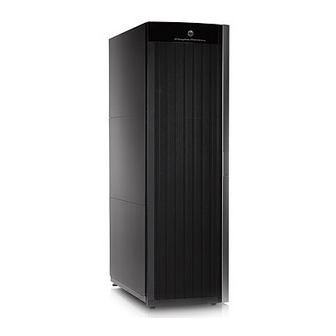
System specifications and requirements This section describes the physical characteristics of a P9500 disk array, including “Mechanical specifications” (page 20) “Electrical specifications” (page 22) “Environmental specifications” (page 26) Mechanical specifications The following table lists the mechanical specifications of the P9500 disk array. Table 9 P9500 mechanical specifications Dimension One Rack... - Page 21 Figure 4 P9500 disk array NOTE: Each Rack is 600mm wide without side covers. Add 5mm to each end of entire assembly for each side cover. System specifications and requirements...
-
Page 22: Electrical Specifications
Figure 5 Example P9500 disk array configurations Electrical specifications “System heat and power specifications” (page 22) “System components heat and power specifications ” (page 22) list the heat and power specifications for the P9500 disk array and components. Table 10 System heat and power specifications Full Array (DKC-0 plus DKC-1 plus DKU... - Page 23 Table 11 System components heat and power specifications (continued) Power Heat Output Consumption Component Product (kW) (kVA) Number P9500 Disk Array Component AV412B Complete 2.5in Drive Chassis 0.57 0.600 AV413A Drive Chassis SAS Switch Kit 0.120 0.103 AV423A, AV423B 8-port 2-8 Gbps FC CHA 0.072 0.076 AV424A, AV424B...
-
Page 24: Grounding
Table 11 System components heat and power specifications (continued) Power Heat Output Consumption Component Product (kW) (kVA) Number P9500 Disk Array Component Power is consumed during the battery back-up time only. Actual values at a typical I/O condition. (Random Read and Write, 50 IOPSs for HDD, 2500 IOPSs for SSD, Data Length: 8 KB). - Page 25 Table 12 P9500 AC PDU Options (continued) Number of Branch circuit Facility PDU per Product requirements receptacle Rack Number Local Power per PDU Plug Type needed Notes Distribution System AV405A 3 phase (5 380-415V, 3Ø, IEC60309 4 IEC60309 4 For customers AV405AU wire) 5-wire, 16A...
-
Page 26: Environmental Specifications
*1 (right): When connected correctly, one of the four PDUs can supply power to the DKC-DKU rack. Environmental specifications Table 13 (page 26) provides the environmental specifications and requirements for the P9500 disk array. Table 13 P9500 environmental specifications Item Operating Not Operating In Storage... - Page 27 and exits through the perforations in the rear door. Either the front fans or the rear fans can cool the chassis by themselves. The racks do not contain fans. Airflow is from front to back. Table 14 Heat, power, and airflow Model Number Heat Output (kW) Power Consumption (kVA)
- Page 28 Table 14 Heat, power, and airflow (continued) Model Number Heat Output (kW) Power Consumption (kVA) Air Flow (M3/min) AV443A - P9500 2nd SVP 0.052 0.055 High Reliability Kit AV444A - P9500 Cache 0.068 0.072 Memory Adapter AV447A, AV447B - P9500 0.019 0.020 16GB Cache Memory...
-
Page 29: Equipment Noise
Table 14 Heat, power, and airflow (continued) Model Number Heat Output (kW) Power Consumption (kVA) Air Flow (M3/min) Power is consumed during the battery back-up time only. Actual values at a typical I/O condition. (Random Read and Write, 50 IOPSs for HDD, 2500 IOPSs for SSD, Data Length: 8Kbytes). - Page 30 Figure 7 Service clearances for a single rack system *1 Clearance (a+b) is based on the floor load rating and the clearance (c). Floor load rating and required clearances are shown in Table 16 (page 30). *2 Clearance (d) is required over 300mm to open the front door. In the case that the clearance (d) is less tan the clearance (a), give priority to clearance (a).
-
Page 31: Two Rack Configuration (One Dkc)
Table 16 Floor load rating and required clearances for single rack configuration (continued) Floor Load Required Clearance (a+b) m Rating Clearance (c) m (kg/m2) C=0.2 C=0.4 C=0.6 C=0.6 Notes: 1. Actual clearances for installation should be determined after consulting with construction specialist responsible for installation building, as they could vary depending on the size/layout of the system and building conditions. - Page 32 Figure 8 Service clearances for a two rack system (single DKC) *1 Clearance (a+b) is based on the floor load rating and the clearance (c). Floor load rating and required clearances are shown in Table 17 (page 32). *2 Clearance (d) is required over 300mm to open the front door. In the case that the clearance (d) is less tan the clearance (a), give priority to clearance (a).
-
Page 33: Two Rack Configuration (Two Dkc)
Table 17 Floor load rating and required clearances for two rack configuration (continued) Floor Load Required Clearance (a+b) m Rating Clearance (c) m (kg/m2) C=0.2 C=0.4 C=0.6 C=0.6 Notes: 1. Actual clearances for installation should be determined after consulting with construction specialist responsible for installation building, as they could vary depending on the size/layout of the system and building conditions. - Page 34 Figure 9 Service clearances for a two rack system (two DKC) *1 Clearance (a+b) is based on the floor load rating and the clearance (c). Floor load rating and required clearances are shown in Table 18 (page 34). *2 Clearance (d) is required over 300mm to open the front door. In the case that the clearance (d) is less tan the clearance (a), give priority to clearance (a).
-
Page 35: Three Rack Configuration (Left Module)
Table 18 Floor load rating and required clearances for a two rack configuration (two DKC) (continued) Floor Load Required Clearance (a+b) m Rating Clearance (c) m (kg/m2) C=0.2 C=0.4 C=0.6 C=0.6 Notes: 1. Actual clearances for installation should be determined after consulting with construction specialist responsible for installation building, as they could vary depending on the size/layout of the system and building conditions. -
Page 36: Three Rack Configuration (Right Module)
*1 Clearance (a+b) is based on the floor load rating and the clearance (c). Floor load rating and required clearances are shown in Table 19 (page 36). *2 Clearance (d) is required over 300mm to open the front door. In the case that the clearance (d) is less tan the clearance (a), give priority to clearance (a). - Page 37 Figure 11 Service clearances for a three rack system (right module) *1 Clearance (a+b) is based on the floor load rating and the clearance (c). Floor load rating and required clearances are shown in Table 20 (page 37). *2 Clearance (d) is required over 300mm to open the front door. In the case that the clearance (d) is less tan the clearance (a), give priority to clearance (a).
-
Page 38: Four Rack Configuration (Left Module)
Table 20 Floor load rating and required clearances for a three rack configuration (right module) (continued) Floor Load Required Clearance (a+b) m Rating Clearance (c) m (kg/m2) C=0.2 C=0.4 C=0.6 C=0.6 Notes: 1. Actual clearances for installation should be determined after consulting with construction specialist responsible for installation building, as they could vary depending on the size/layout of the system and building conditions. -
Page 39: Four Rack Configuration (Right Module)
*1 Clearance (a+b) is based on the floor load rating and the clearance (c). Floor load rating and required clearances are shown in Table 21 (page 39). *2 Clearance (d) is required over 300mm to open the front door. In the case that the clearance (d) is less tan the clearance (a), give priority to clearance (a). - Page 40 Figure 13 Service clearances for a four rack system (right module) *1 Clearance (a+b) is based on the floor load rating and the clearance (c). Floor load rating and required clearances are shown in Table 22 (page 40). *2 Clearance (d) is required over 300mm to open the front door. In the case that the clearance (d) is less tan the clearance (a), give priority to clearance (a).
- Page 41 Table 22 Floor load rating and required clearances for a four rack configuration (right module) (continued) Floor Load Required Clearance (a+b) m Rating Clearance (c) m (kg/m2) C=0.2 C=0.4 C=0.6 C=0.6 Notes: 1. Actual clearances for installation should be determined after consulting with construction specialist responsible for installation building, as they could vary depending on the size/layout of the system and building conditions.
-
Page 42: Five Rack Configuration
Five rack configuration This following figure and table shows the service clearances and floor load rating for a five-rack configuration. Figure 14 Service clearances for a five rack system *1 Clearance (a+b) is based on the floor load rating and the clearance (c). Floor load rating and required clearances are shown in Table 23 (page 43). -
Page 43: Six Rack Configuration
Table 23 Floor load rating and required clearances for a five rack configuration Floor Load Required Clearance (a+b) m Rating Clearance (c) m (kg/m2) C=0.2 C=0.4 C=0.6 C=0.6 0 .1 Notes: 1. Actual clearances for installation should be determined after consulting with construction specialist responsible for installation building, as they could vary depending on the size/layout of the system and building conditions. - Page 44 Figure 15 Service clearances for a six rack system *1 Clearance (a+b) is based on the floor load rating and the clearance (c). Floor load rating and required clearances are shown in Table 24 (page 44). *2 Clearance (d) is required over 300mm to open the front door. In the case that the clearance (d) is less tan the clearance (a), give priority to clearance (a).
-
Page 45: Operational Requirements
Table 24 Floor load rating and required clearances for a six rack configuration (continued) Floor Load Required Clearance (a+b) m Rating Clearance (c) m (kg/m2) C=0.2 C=0.4 C=0.6 C=0.6 0 .1 Notes: 1. Actual clearances for installation should be determined after consulting with construction specialist responsible for installation building, as they could vary depending on the size/layout of the system and building conditions. -
Page 46: Power On/Off Procedures
4 Power On/Off procedures Safety and environmental information CAUTION: Before operating or working on the P9500 disk array, read the safety section in theP9500 site preparation guide and the environmental information in ???. Standby mode When the disk array power cables are plugged into the PDUs and the PDU breakers are ON, the disk array is in standby mode. -
Page 47: Power Off Procedures
Follow this procedure exactly when powering the disk array on. Refer to the illustration of the control panel as needed. On the control panel, check the amber BS LED and make sure it is lit. It indicates that the disk array is in standby mode. In the PS area on the control panel, move the Enable switch to the ENABLED position. -
Page 48: Cache Destage Batteries
prevent slow data throughout in the cache. When the battery charge is 50% or more, the cache write protect mode operates normally. When a power failure occurs and continues for 20 milliseconds or less, the disk array continues normal operation. If the power failure exceeds 20 milliseconds, the disk array uses power from the batteries to back up the cache memory data and disk array configuration data to the cache flash memory on each cache board. -
Page 49: Long Term Array Storage
NOTE: The disk array generates a SIM when the cache destage batteries are not charged to at least 50%. The LEDs on the front panel of the cache boards also show the status of the batteries. Long term array storage While connected, the cache destage batteries will completely discharge in two to three weeks without power applied. -
Page 50: Technical Specifications
5 Technical Specifications This chapter describes the physical, electrical, and operating specifications of an P9500 disk array. Mechanical specifications The following table lists the mechanical specifications of the P9500 disk array. Table 26 P9500 mechanical specifications Dimension Single Rack Single Module Dual Module (3 racks) (6 racks) - Page 51 System components heat and power specifications Table 28 System components heat and power specifications Power Heat Output Consumption Component Product (kW) (kVA) Number P9500 Disk Array Component AV375A Flash Module Chassis 0.600 0.640 AV392A, AV393A Flash Module 0.017 0.018 AV400A Disk Array DKC Module-0 Rack 1.88 1.97...
- Page 52 Table 28 System components heat and power specifications (continued) Power Heat Output Consumption Component Product (kW) (kVA) Number P9500 Disk Array Component AV483A 300GB SAS 15K 2.5in DP HDD 0.0086 0.0090 AV490A 200GB SAS 2.5in DP SLC SSD 0.0127 0.0134 AV491A 400GB SAS 2.5in DP SLC SSD 0.0023...
- Page 53 Table 29 P9500 AC PDU options (continued) Number of Branch circuit Facility PDU per Product requirements receptacle Rack Number Local Power per PDU Plug Type needed Notes IEC60309 32A plug Notes: 1. Each PDU has one fixed power cord with attached plug. Power cord is not removable. NOTE: PDU models can be changed in the field using offline maintenance procedures.
- Page 54 Table 30 P9500 environmental specifications (continued) Item Operating Not Operating In Storage Max. Wet Bulb 78.8 / 26 80.6 / 27 84.2 / 29 (ºF / ºC) Temperature 50 / 10 50 / 10 68 / 20 Deviation per hour) (ºF / ºC) Vibration 10 to 300 Hz...
-
Page 55: Technical Specifications
A Technical Specifications Mechanical specifications The following table lists the mechanical specifications of the P9500 disk array. Table 31 P9500 mechanical specifications Dimension Single Rack Single Module Dual Module (3 racks) (6 racks) Width (inches / mm) 24.0 / 610 71.3 / 1810 142 / 3610 Depth (inches / mm) -
Page 56: System Components Heat And Power Specifications
System components heat and power specifications Table 33 System components heat and power specifications Power Heat Output Consumption Component Product (kW) (kVA) Number P9500 Disk Array Component AV375A Flash Module Chassis 0.600 0.640 AV392A, AV393A Flash Module 0.017 0.018 AV400A Disk Array DKC Module-0 Rack 1.88 1.97... -
Page 57: Ac Power - Pdu Options
Table 33 System components heat and power specifications (continued) Power Heat Output Consumption Component Product (kW) (kVA) Number P9500 Disk Array Component AV483A 300GB SAS 15K 2.5in DP HDD 0.0086 0.0090 AV490A 200GB SAS 2.5in DP SLC SSD 0.0127 0.0134 AV491A 400GB SAS 2.5in DP SLC SSD 0.0023... -
Page 58: Environmental Specifications
Table 34 P9500 AC PDU options (continued) Number of Branch circuit Facility PDU per Product requirements receptacle Rack Number Local Power per PDU Plug Type needed Notes IEC60309 32A plug Notes: 1. Each PDU has one fixed power cord with attached plug. Power cord is not removable. NOTE: PDU models can be changed in the field using offline maintenance procedures. - Page 59 Table 35 P9500 environmental specifications (continued) Item Operating Not Operating In Storage (ºF / ºC) Temperature 50 / 10 50 / 10 68 / 20 Deviation per hour) (ºF / ºC) Vibration 10 to 300 Hz 5 to 10 Hz: 2.5 mm Sine Vibration: to 10Hz: 0.25 mm 0.49 m/s...
-
Page 60: B Warranty And Regulatory Information
B Warranty and regulatory information For important safety, environmental, and regulatory information, see Safety and Compliance Information for Server, Storage, Power, Networking, and Rack Products, available at www.hpe.com/support/Safety-Compliance-EnterpriseProducts. Warranty information HPE ProLiant and x86 Servers and Options www.hpe.com/support/ProLiantServers-Warranties HPE Enterprise Servers www.hpe.com/support/EnterpriseServers-Warranties HPE Storage Products www.hpe.com/support/Storage-Warranties... -
Page 61: Turkey Rohs Material Content Declaration
Local representative information Kazakh: Russia: Belarus: Kazakhstan: Manufacturing date: The manufacturing date is defined by the serial number. CCSYWWZZZZ (serial number format for this product) Valid date formats include: YWW, where Y indicates the year counting from within each new decade, with 2000 as the starting point;...
Need help?
Do you have a question about the HPE XP P9500 and is the answer not in the manual?
Questions and answers