Table of Contents
Advertisement
Advertisement
Chapters
Table of Contents

Related Manuals for Parker iqan-mc3


Summary of Contents for Parker iqan-mc3
- Page 1 IQAN-MC3 Instruction book Publ no HY33-8001-IB/UK Edition 2016-05-16...
-
Page 2: Table Of Contents
Reverse feed ..........26 IQAN-MC3 addressing/terminating ....... 26 Use of an ID-Tag . - Page 3 Appendix A ........... 46 IQAN-MC3 Technical Overview ........46 Appendix B .
-
Page 4: Introduction
In some cases we put a warning next to a SMR. This is done where there is a need to emphasize that the safety information is just as important when the module is used for normal (non-safety related) functions. Instruction book, IQAN-MC3... -
Page 5: Overview Of Relevant Documentation
Contact the manufacturer if there is anything you are not sure about or if you have any questions regarding the product and its handling or maintenance. The term "manufacturer" refers to Parker Hannifin Corporation. Overview of relevant documentation The following publications are relevant for users of this product. -
Page 6: Precautions
The machine must be equipped with an emergency stop that stops all movement. Please refer to section Emergency stop, on page 25. Before you start Read this document, as a minimum sections 1-7 Read the IQANdesign software user manual section on 'application safety'. Instruction book, IQAN-MC3... -
Page 7: Start-Up, Maintenance, And Diagnostics
Mounting and maintenance instruction book. Additional information for diagnosing the system Read section Diagnostics and troubleshooting, on page 45, and see Appendix B, on page 51, in this document. Use the IQANrun software user manual as a reference. Instruction book, IQAN-MC3... -
Page 8: Product Description
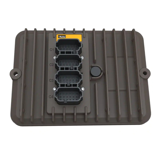
The IQAN-MC3 is a SIL2 rated master module in the IQANdesign platform. It can be used as a standalone controller, as a single bus master, or together with other IQAN master modules. -
Page 9: Communication
Product description Inputs All of the 32 inputs on the IQAN-MC3 can be used for safety related signals, when the inputs are configured in pairs. On the unit there are 16 analog inputs for 0-5 V signals from e.g. hall-effect or potentiometer sensors;... -
Page 10: Safety
The IQAN-MC3 is designed for use in safety functions of up to SIL2 (IEC 61508). The IQAN-MC3 in itself does not come with any safety function; it needs to be put into a system and loaded with an application file. -
Page 11: System Boundaries
• Measurement of module supply voltage • Measurement of module temperature The following built in functionality of the IQAN-MC3 is seen as non-safety related: • Logs • LED diagnostics OTICE The IQAN-MC3 does not come with any pre existing safety function implemented. -
Page 12: Architecture For A Complete Safety Function
The IQAN-MC3 is suitable for connection to input subsystems of category 2, 3 or 4 in accordance with EN ISO13849-1, up to PLd. If inputs are connected as a Category B subystem, that will restrict the overall PL to a lower level. -
Page 13: Mc3-Smr-005:A Only Use An Official Release Of Iqandesign
Logic subsystem, IQAN-MC3 and application software The logic subsystem consists of the IQAN-MC3 and the application software. The hardware and embedded software of the IQAN-MC3 allows it to be used to implement safety functions of up to SIL2 or PLd. -
Page 14: Local Physical Inputs Used As Part Of Input Subsystem In Safety Functions
(e.g. valve) The IQAN-MC3 module connected to output subsystem. The IQAN-MC3 is suitable for connection to output subsystems of category B, 1, 2, 3 or 4 in accordance with EN ISO13849-1, up to PLd. Local physical inputs used as part of input subsystem in safety functions This section describes the concept for how to use the IQAN-MC3 inputs (e.g. -
Page 15: Can Communication
VIN secondary -VREF Connecting pairs of signals. The wiring is the same for both alternatives. CAN communication The IQAN-MC3 has built in support for safe connection to other IQAN-MC3 units. For more information, see the IQANdesign user manual. Instruction book, IQAN-MC3... -
Page 16: Outputs
Safe communication between IQAN-MC3 units, one CAN bus used CAN communication between multiple IQAN-MC3 master modules. The IQAN-MC3 can be used for connection to sensor subsystems over CAN, assuming that the CAN protocol is suitable for safety related communication and that the diagnostic features in that protocol are able to be implemented on the IQAN-MC3. -
Page 17: Internal Diagnostics
Internal diagnostics The concept of the IQAN-MC3 is that the primary CPU is monitored by a second, independent CPU; and they in turn are monitored by a completely separate safety ASIC. -
Page 18: Markings/Approvals
Markings/Approvals Safety Markings/Approvals Instruction book, IQAN-MC3... - Page 19 Markings/Approvals Safety Instruction book, IQAN-MC3...
- Page 20 Markings/Approvals Safety Instruction book, IQAN-MC3...
- Page 21 Markings/Approvals Safety Instruction book, IQAN-MC3...
- Page 22 Markings/Approvals Safety Instruction book, IQAN-MC3...
-
Page 23: Mounting
• For maximum cooling, mount the module on a vertical surface. • Locate the module so that the LEDs are visible. Recommended placing. OTICE The IQAN-MC3 module must not be placed in any marine related or similar continuously damp, salt-spray environment without external protection. Instruction book, IQAN-MC3... -
Page 24: Installation
+BAT Power supply 12/24 Vdc DOUT-D DOUT power driver (type B), high side DRET-D DOUT power driver (type B), low side DOUT-E DOUT power driver (type B), high side DRET-E DOUT power driver (type B), low side Instruction book, IQAN-MC3... -
Page 25: Connector C2 Pin Assignments
Voltage signal input VIN-H Voltage signal input VIN-I Voltage signal input VIN-J Voltage signal input VIN-K Voltage signal input VIN-L Voltage signal input VIN-M Voltage signal input VIN-N Voltage signal input VIN-O Voltage signal input VIN-P Voltage signal input Instruction book, IQAN-MC3... -
Page 26: Connector C3 Pin Assignments
DIN / FIN / DFIN / PCN /DPCN signal input DIN-I Digital signal input DIN-J Digital signal input DIN-K Digital signal input DIN-L Digital signal input DIN-M Digital signal input DIN-N Digital signal input DIN-O Digital signal input DIN-P Digital signal input Instruction book, IQAN-MC3... -
Page 27: Connector C4 Pin Assignments
DOUT power driver (type B), low side DOUT-B DOUT power driver (type B), high side DRET-B DOUT power driver (type B), low side DOUT-C DOUT power driver (type B), high side DRET-C DOUT power driver (type B), low side Instruction book, IQAN-MC3... -
Page 28: I/O Configuration
+B AT Emergency stop. Since the IQAN-MC3 is capable of implementing safety functions, it may in some applications be tempting for the designer to implement the emergency stop as a function in the IQAN-MC3. The IQAN-MC3 does not have any built in emergency stop function, but if it is implemented anyway, it must be done with extreme caution. -
Page 29: Connecting Of Supply Voltage
If any of the outputs are shorted to battery voltage, the module will be powered by reverse feed of voltage, even when the connection to module power is off. The IQAN-MC3 is capable of detecting if outputs are shorted to battery voltage at start- up, and will prevent the application from starting. -
Page 30: Terminating
When an IQANdesign application is loaded, it can set individual buses to be non-terminated. To give an IQAN-MC3 a unique address, you may use an addressing ID-tag, or an ID- tag having a combined address and terminating function. The ’T’ values of ID-tags are ignored, i.e. -
Page 31: O Functionality
This section contains information about how to connect and use the I/O, with specific additional information about rules that apply when the I/O is used in a safety function. Inputs There are 3 types of inputs in the IQAN-MC3: • Voltage inputs • Digital inputs •... -
Page 32: Using Voltage Inputs In Safety Functions
It is recommended that the connected sensors shall use one of the VREF’s from the IQAN-MC3, especially when voltage inputs are used in safety functions. If an external 5 V reference is used, it is up to the application to ensure that the reference voltage is correct. -
Page 33: Mc3-Smr-008:A Tolerances On Vin
A voltage input may be connected to a switch, but it shall use +VREF, the switch may not be connected to +BAT. OTICE The VIN are designed for permanent connection to +BAT, but not for +BAT transients. Therefore VIN connection to +BAT should be avoided. Instruction book, IQAN-MC3... - Page 34 The switches are connected to +VREF and VIN/DIN respectively for 5V signal. EXAMPLE Connect the positive and negative terminals of the switch to +VREF and VIN, respectively. IQAN-MC3 +VREF Connecting a switch to VIN and VREF. OTICE Maximum load for VREF position, see Appendix A, on page 46. Instruction book, IQAN-MC3...
-
Page 35: Digital Inputs
If the additional signal is read by another digital input, it is recommended that the signals are not equal. For example, use linked normally open and normally closed switches. Instruction book, IQAN-MC3... -
Page 36: Frequency Inputs
Connecting sensors to the directional frequency inputs Directional frequency inputs can operate in 2 modes. Speed which is frequency and position which is a pulse count. For the frequency ranges and trigger levels, see Appendix A, on page 46. Instruction book, IQAN-MC3... -
Page 37: Using Directional Frequency Inputs In Safety Functions
MC3-SMR-011:A Use of DFIN inputs in pairs When directional frequency inputs are used in safety functions, the application shall be designed so that the input signals are compared to an additional signal to ensure that it is correct. Instruction book, IQAN-MC3... -
Page 38: Reference Voltage, Vref
I/O functionality Reference voltage, VREF The IQAN-MC3 is internally equipped with voltage regulators to generate the reference voltage VREF. The standard 5V reference voltage will feed different kinds of sensors. There is a VREF connection in both the C2 connector, and the C3 connector. -
Page 39: Outputs
Appendix A, on page 46. Frequency To obtain the best performance from proportional valves the IQAN-MC3 produces a current mode (closed loop) output signal. The units have an adjustable frequency which can be changed using IQAN software. - Page 40 In PWM mode, the current is not measured, and diagnostics are limited. OTICE The PWM outputs on an IQAN-MC3 can not be used to drive Pulsar valves, select another IQAN module to do that. COUT mode output diagnostics The COUT is capable of detecting internal faults as well as wiring faults.
-
Page 41: Use Of Cout In Safety Functions
’under/over current threshold’, see Appendix A, on page 46. An undetected error that falls within these limits can lead to an unintentional change of speed of the output, and must be safe in the application for which the IQAN-MC3 is used. - Page 42 The COUT current range and slopes must be limited in the application file. Due to the risks involved with modifying these adjustable values, it is recommended that these limits are kept narrow. Alternatively, the access to modification of current range and slopes can be limited. See IQANdesign user manual. Instruction book, IQAN-MC3...
-
Page 43: Digital Outputs
I/O functionality Digital outputs The IQAN-MC3 has two types of digital outputs. While all of the digital outputs are designed to drive coils for on-off valves, DOUT D-E are also designed to drive indicators such as LED’s. For current ratings on the DOUT’s, see Appendix A, on page... -
Page 44: Use Of Dout In Safety Functions
You should also note that there are wiring errors that can only be detected on start-up of the unit. Undetected wiring faults There are DOUT wiring faults that are not detectable by the IQAN-MC3, and there are faults that are only detected at startup, see Appendix B, on page 51. MC3-SMR-017:A DOUT undetected wiring faults The application shall be designed so that undetected wiring errors on DOUT are safe. -
Page 45: Start-Up
The emergency stop should disconnect the supply voltage to all modules. IQAN-MC3 Emergency stop +BAT Dump valve Emergency stop. Alternatively, the emergency stop may also shut off the diesel engine or a dump valve, and with that depressurize the hydraulic system. Instruction book, IQAN-MC3... -
Page 46: Prepare For System Start
• In addition to these measures, the machine shall also meet the machine directives for the country in question. ARNING Work on the hydraulics control electronics may only be carried out by trained personnel who are well-acquainted with the control system, the machine and its safety regulations. Instruction book, IQAN-MC3... -
Page 47: Check List For Electronics
- Functions are positioned safely. - The machine is turned off. - The hydraulic system is relieved from any pressure. Check that electrical output signal correspond Start machine equal with hydraulic direction. engine Tune current settings and slope times. Engine ON Instruction book, IQAN-MC3... -
Page 48: Diagnostics And Troubleshooting
CAN diagnostics connection One of the 4 CAN buses of the IQAN-MC3 may be dedicated for diagnostics. Reserving a bus for diagnostics ensures that signals are not interrupted by other bus traffic. -
Page 49: Iqan-Mc3 Technical Overview
IQAN-MC3 Technical Overview Appendix A Appendix A IQAN-MC3 Technical Overview Absolute Maximum Ratings Ambient temperature, -40 to +85 °C Storage temperature -40 to +100 °C Voltage supply on +BAT 6 to 36 Vdc Voltage on any pin with respect to -BAT... - Page 50 IQAN-MC3 Technical Overview Appendix A System = -40 to +85 °C (unless otherwise specified) Weight 1.1 kg Ambient temperature, T -40 to +85 °C Voltage supply on +BAT, V 9 to 32 Vdc Current supply =14V typ. 250 mA typ. 170 mA...
- Page 51 IQAN-MC3 Technical Overview Appendix A Signal input, DIN Number of DIN 16 (configuration may reduce number) Logic levels <1 V high >4 V hysteresis >0.1 V Input impedance 6.8 kohm in parallel with 10 nF Sample rate same as system cycle time T...
- Page 52 IQAN-MC3 Technical Overview Appendix A Power driver, COUT Number of COUT 4 dual outputs COUT range 100 mA high 2000 mA COUT resolution 1 mA Power driver voltage drop 750 mA load typ. 0.45 V @ saturation 1500 mA load typ.
- Page 53 IQAN-MC3 Technical Overview Appendix A Power driver, DOUT Number of DOUT Maximum load DOUT-A to DOUT-C 3.0 A DOUT-D to DOUT-E 1.5 A Power driver voltage drop DOUT-A to DOUT-C typ. 0.70 V @ 3 A load DOUT-D to DOUT-E typ.
-
Page 54: Error Codes, Messages And Actions
Error description Output Input VREF Power Supply Temperature CAN, no contact IDtag error System mismatch CAN error (bus off) Internal error/OSE Critical Temperature Critical Stop a.Possible cause of 4:3 error is reverse feed of voltage on start-up. Instruction book, IQAN-MC3... -
Page 55: Failure Modes
Failure modes Appendix B Failure modes The following tables have information about the actions taken by the IQAN-MC3 when certain failure causing conditions occur. Failure modes for single inputs OTICE For safety functions, VIN is the only input type that may be used without another input as comparison. -
Page 56: Frequency Input
* DFIN short circuit to signal within low to Undefined ** high trigger level range * DFIN short circuit to signal < low trigger Frequency 0 level * DFIN short circuit to -BAT Frequency 0 ** Instruction book, IQAN-MC3... -
Page 57: Failure Modes For External Wiring Faults On Power Drivers - Cout
Ability to shut down in the event of an internal error reduced. Detected at next start-up Current output Start-up Failure mode Detected Comment COUT short circuit to +BAT at start-up • Module prevented from starting. CRET short circuit to +BAT at start-up • Module prevented from starting. Instruction book, IQAN-MC3... - Page 58 COUT/DOUT). No influence on function in this state. COUT short circuit to 2 CRET/DRET (passive) • CRET short circuit to 2 CRET/DRET (active) No influence on function in this state. CRET short circuit to 2 CRET/DRET (passive) Instruction book, IQAN-MC3...
- Page 59 CRET open • CRET short circuit to +BAT Reverse feed *. No influence on function in this state. CRET short circuit to -BAT • No influence on function in this state. CRET short circuit to 2 CRET (passive) Instruction book, IQAN-MC3...
-
Page 60: Failure Modes For External Wiring Faults On Power Drivers - Dout
Ability to shut down in the event of an internal error reduced. Detected at next start-up Digital output Start-up Failure mode Detected Comment DOUT short circuit to +BAT at start-up • Module prevented from starting. DRET short circuit to +BAT at start-up • Module prevented from starting. Instruction book, IQAN-MC3... - Page 61 DRET (active) No influence on function in this state. DOUT short circuit to 2 CRET/DRET (passive) • DRET short circuit to 2 DRET (active) No influence on function in this state. DRET short circuit to 2 CRET/DRET (passive) Instruction book, IQAN-MC3...
- Page 62 DRET (active) No influence on DOUT (error detected DRET short circuit to 2 CRET (active) on 2 COUT). No influence on function in this state. DRET short circuit to 2 CRET/DRET (passive) Insufficient voltage on +BAT • Instruction book, IQAN-MC3...
- Page 63 DRET (active) No influence on DOUT (error detected DRET short circuit to 2 CRET (active) on 2 COUT). No influence on function in this state. DRET short circuit to 2 CRET/DRET (passive) Insufficient voltage on +BAT Under current Instruction book, IQAN-MC3...
-
Page 64: Dimensioning Of The Iqan-Mc3 Module
Dimensioning of the IQAN-MC3 module Appendix C Appendix C Dimensioning of the IQAN-MC3 module IQAN-MC3 Ø 6.5 unit = mm Instruction book, IQAN-MC3... -
Page 65: Safety Manual Requirements
MC3-SMR-013:A COUT error detection limits ..........38 MC3-SMR-014:A COUT undetected wiring faults.......... 38 MC3-SMR-015:A Minimum current when using DOUT as power driver ..41 MC3-SMR-016:A DOUT used as alarm drivers ..........41 MC3-SMR-017:A DOUT undetected wiring faults.......... 41 Instruction book, IQAN-MC3... - Page 66 For the latest information visit our website www.iqan.com Information in this instructionbook is subject to change without notice Publ no HY33-8001-IB/UK Edition 2016-05-16 Parker Hannifin Parker Hannifin Electronic Controls Division Electronic Controls Division SE-435 35 Mölnlycke 1651 N. Main Street...
Need help?
Do you have a question about the iqan-mc3 and is the answer not in the manual?
Questions and answers