Sign In
Upload
Download
Table of Contents
Contents
Add to my manuals
Delete from my manuals
Share
URL of this page:
HTML Link:
Bookmark this page
Add
Manual will be automatically added to "My Manuals"
Print this page
×
Bookmark added
×
Added to my manuals
Manuals
Brands
Parker Manuals
Controller
IPA04-HC
Hardware installation manual
Parker IPA04-HC Hardware Installation Manual
Intelligent amplifier
Hide thumbs
1
2
3
4
5
6
Table Of Contents
7
8
9
10
11
12
13
14
15
16
17
18
19
20
21
22
23
24
25
26
27
28
29
30
31
32
33
34
35
36
37
38
39
40
41
42
43
44
45
46
47
48
49
50
51
52
53
54
55
56
57
58
59
60
61
62
63
64
65
66
67
68
69
70
71
72
73
74
75
76
77
78
79
80
81
82
83
84
85
86
87
88
89
90
91
92
93
94
95
96
97
98
99
100
101
102
103
104
105
106
107
108
109
110
111
112
113
114
115
116
117
118
119
120
121
122
123
124
125
126
127
128
page
of
128
Go
/
128
Contents
Table of Contents
Troubleshooting
Bookmarks
Table of Contents
User Information
Contact Information for Technical Assistance
Symbols
Description
Important Safety Information
Table of Contents
Contents
CHAPTER 1 Introduction
IPA Controllers-Overview
IPA Product Description
IPA Part Numbers
Input Power Level
Output Power Level
Servo Motor Drives
Components
Options
Checking Your Shipment
Illustrations in this Installation Guide
Assumptions of Technical Experience
Technical Support
CHAPTER 2 Mechanical Installation
Environment & Drive Cooling
Cabinet Cooling
IPA04-HC Model
IPA15-HC Model
Cabinet Cooling Calculations
Dimensions
Drive Dimensions
Weight
Mounting Guidelines
Cable Routing
Panel Routing
CHAPTER 3 Electrical Installation
Installation Safety Requirements
Precautions
System Installation Overview
Connectors
X1 - Output Power Connector
X2 - Input Power / Mains Connector
Factory Installed Jumpers
X6 - Motor Feedback Connector
Motor Feedback Connector Pinout
Internal Connections
Encoder Inputs
Motor Power & Feedback Cables
X5 - Drive I/O Connector
Sample Wiring
Drive I/O Cable
Drive I/O Connector Pinout
Internal Connections
Inputs-High-Speed/Auxiliary Encoder
Inputs-General Purpose
Outputs-General Purpose
X7 - Auxiliary (Control Power, Torque Enable, Analog Input)
Output (Motor) Power
Output Power Ratings
Output (Motor) Power Connections
Power Supply
Input Power
Fuse Requirements
Motor Power Fuse Information
Control Power Fuse Information
Drive Inrush Current
Power Supply Connections
Earth Ground
Single-Source (Motor Input Power) Connections
Separate Sources Connections
Multiple Drive/Controller Installations
Safety Earth Connection
Brake Relay (Optional)
Brake Relay Connector (on Output Power Connector)
Brake Relay Operation
Brake Relay Specifications
Brake Relay Connection
Brake Relay to Motors with Full Wave Rectifiers
Brake Relay to Motors Without Full Wave Rectifiers
Regeneration Protection
Regeneration Connection
Internal Regeneration Capability
CHAPTER 4 Communications
Overview
Ethernet Specifications
Ethernet Cable Specification
Ethernet Connector
Ethernet Connector Pinout
RJ-45 LED Ethernet Status Indicators
Assigning IP Addresses
Setting the IP Address- IPA
Setting the IP Address and Subnet Mask-PC
Connecting to a PC
Verifying the IP Address
LED Status Indicators
Ethernet Network Status
Drive/Controller Status
CHAPTER 5 Troubleshooting
General Troubleshooting Guidelines
Power
Communications
RJ-45 Ethernet Status Leds
Ethernet Network Status LED
ACR-View
Motor Control
Fault Correction
Error Codes
Hall Sensors
Troubleshooting Checklist
Possible Problems
Procedures
CHAPTER 6 Torque Enable Safety Circuitry
Torque Enable Functional Description
User Connections
Torque Enable Technical Specification
Ideal Operation
Typical Operation
Fault Operation
CHAPTER 7 Additional Specifications
Amplifier
Performance
Protective Circuits
Short Circuit Protection
Resetting the Fault
Drive/Controller Over-Temperature Protection
Threshold Temperature
Under-Voltage Protection
Threshold Voltage
Resetting the Fault
Over-Voltage Protection
Threshold Voltage
Resetting the Fault
Current Foldback
Cables
EMC Ready Cables
Non-EMC Cables
CHAPTER 8 Regulatory Compliance UL and CE
System Installation Overview
General Safety Considerations
General EMC Considerations
Installing the IPA Drive
Precautions
A Safe Installation - Meeting the Requirements of the Low Voltage Directive (LVD)
A Highly-Immune, Low-Emission Installation - Meeting the Requirements of the Electromagnetic Compatibility (EMC) Directive
Control Power
Mains Motor Power
Panel Installation, IPA04-HC to IPA15-HC
Panel Mounting
Regulatory Agencies
Standards of Compliance
APPENDIX A VM25 Expansion Module
Overview
APPENDIX B IPA with Iforce or Ripped Linear Servos
Iforce/Ripped to IPA-Controller Wiring
Limit and Home Sensor Connections
IPA Thermal Model Protection and Power Installation
Software Configuration: Select Coil Part Number
Software Configuration: Set Feedback Resolution
Software Configuration: Thermal Sensor Type
Software Configuration: Position Error & Soft Limits
Software Configuration: End of Travel (EOT) Limits & Home
APPENDIX C IPA with Parker Mechanics
IPA with Parker Mechanics
Parker Gearhead Gear Ratios
Limit/Home Sensor Wiring
Iforce and Ripped Positioners with Connector Box Option
P8S Global Drop-In Solid State Sensors
P8S Mini-Global Drop-In Solid State Sensors
Advertisement
Quick Links
1
Error Codes
Download this manual
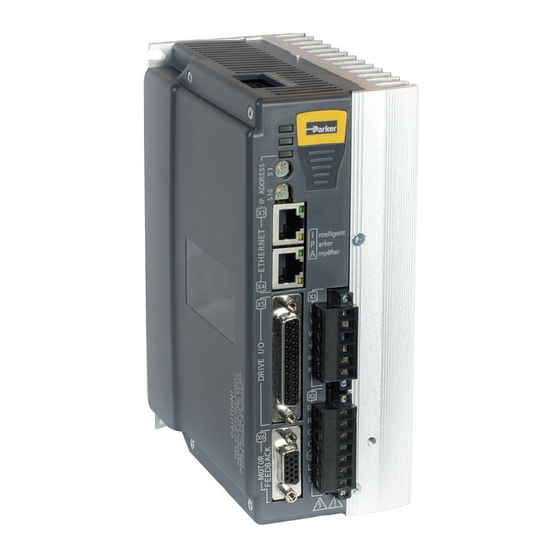
IPA Intelligent Parker Amplifier
Hardware Installation Guide
Effective: December, 2014
Document Number: 88-032500-01A
Table of
Contents
Previous
Page
Next
Page
1
2
3
4
5
Advertisement
Table of Contents
Troubleshooting
CHAPTER 5 Troubleshooting
63
General Troubleshooting Guidelines
64
Hall Sensors
72
Need help?
Do you have a question about the IPA04-HC and is the answer not in the manual?
Ask a question
Questions and answers
Related Manuals for Parker IPA04-HC
Controller parker iqan-mc3 User Manual
Master safety controller (66 pages)
Controller Parker IQAN-XA2 Instruction Book
Expansion controller (39 pages)
Controller Parker IQAN-MC31 Instruction Book
Master controller (41 pages)
Controller Parker IPA Series Hardware Installation Manual
Intelligent amplifier (128 pages)
Controller Parker IQAN-MC2 Instruction Book
(41 pages)
Controller Parker IQAN-LST Instruction Book
(11 pages)
Controller Parker IQAN-XS2 Instruction Book
(31 pages)
Controller Parker 690+ Series Product Manual
(242 pages)
Controller Parker 690+ series Product Manual
Frame b, c, d, e & f (166 pages)
Controller Parker Compumotor AT6250 Installation Manual
Servo controller (59 pages)
Controller Parker AC890 Product Manual
Frequency, frame e & f with sto sil3/ple (710 pages)
Controller Parker 507 Product Manual
Dc controller (33 pages)
Controller Parker HAUSER HPLA Series User Manual
Linear actuator (55 pages)
Controller Parker 512C Technical Manual
Dc controller (37 pages)
Controller Parker LevelController SCLSD Operating Manual
(6 pages)
Controller Parker Sporlan PSK Series Manual
Refrigeration controllers (44 pages)
Table of Contents
Print
Rename the bookmark
Delete bookmark?
Delete from my manuals?
Login
Sign In
OR
Sign in with Facebook
Sign in with Google
Upload manual
Upload from disk
Upload from URL


Need help?
Do you have a question about the IPA04-HC and is the answer not in the manual?
Questions and answers