Table of Contents
Advertisement
Quick Links
Advertisement
Table of Contents

Related Manuals for Advantech ark-3405


Summary of Contents for Advantech ark-3405
- Page 1 User Manual ARK-3405 Fanless Embedded Box PC...
- Page 2 English user manual included as a PDF file on the CD. Please disregard the Chinese hard copy user manual if the product is not to be sold and/or installed in China. 甲類警語 : 警告使用者 : 這是甲類資訊產品,在居住的環境使用時,可能會造成輻射干擾,在這 種情況下,使用者會被要求採取某些適當措施。 ARK-3405 User Manual...
- Page 3 The documentation and the software included with this product are copyrighted 2016 by Advantech Co., Ltd. All rights are reserved. Advantech Co., Ltd. reserves the right to make improvements in the products described in this manual at any time without notice.
-
Page 4: Declaration Of Conformity
Because of Advantech’s high quality-control standards and rigorous testing, most of our customers never need to use our repair service. If an Advantech product is defec- tive, it will be repaired or replaced at no charge during the warranty period. For out- of-warranty repairs, you will be billed according to the cost of replacement materials, service time and freight. -
Page 5: Technical Support And Assistance
Technical Support and Assistance Visit the Advantech web site at www.advantech.com/support where you can find the latest information about the product. Contact your distributor, sales representative, or Advantech's customer service center for technical support if you need additional assistance. Please have the following information ready before you call: –... -
Page 6: Ordering Information
AMO-R020, 1x PCI + 1x PCIex1 riser card 96PSA-A84W12P4 AC to DC Adaptor, DC12V/7A, 84W, 0~40C 1702002600 Power Cord, 3-Pin 183cm, USA type 1702002605 Power Cord, 3-Pin 183cm, EU type 1702031801 Power Cord, 3-Pin 183cm, UK type 1700000237 Power Cord, 3-Pin 183cm, PSE type ARK-3405 User Manual... -
Page 7: Safety Instructions
RESTRICTED ACCESS AREA: The equipment should only be installed in a Restricted Access Area. DISCLAIMER: This set of instructions is given according to IEC 704-1. Advan- tech disclaims all responsibility for the accuracy of any statements contained herein. ARK-3405 User Manual... - Page 8 ARK-3405 User Manual viii...
-
Page 9: Table Of Contents
Figure 2.2 Jumper Layout of Riser Card........10 Connectors....................11 2.3.1 ARK-3405 External I/O Locations ..........11 Figure 2.3 ARK-3405 Front IO connector drawing ....11 Figure 2.4 ARK-3405 Rear IO connector drawing ..... 11 2.3.2 ARK-3405 External I/O connectors..........12 Figure 2.5 Audio connector............ - Page 10 Boot .................... 57 3.1.6 Save & Exit ................. 58 Appendix A Watchdog Timer Sample Code ..59 EC Watchdog Timer Sample Code............60 Appendix B USB 3.0 Drivers Installation Instruction61 USB 3.0 Drivers Installation Instruction ..........62 ARK-3405 User Manual...
-
Page 11: Chapter 1 General Introduction
Chapter General Introduction This chapter gives background information on ARK-3405 series. -
Page 12: Introduction
I/O interface. Various Expansion Support ARK-3405 is a flexible model which can work in different environments and applica- tions with multiple I/O and high performance. It can support three kinds of riser cards: 2 x PCI, 2 x PCIe x1 and 1 PCIx1 + 1 PCIex1. It also has board-to-board design and more I/O ports in a coast line without cables. -
Page 13: Product Features
Storage: 2 x 2.5" removable HDD drive bays (12.5mm height) Expansion Interface: 2 x Full-size MiniPCIe slot, one with SIM holder Software API: Advantech iManager and SUSIAccess - Remote Device Man- agement technology 1.2.2 Display Controller: Intel® HD Graphics 400 ... -
Page 14: Susi 4.0
SUSI 4.0 iManager Sequence control Supported 8-bit programmable DIO Watchdog timer Multi-level WDT (set by Advantech iManager) Programmable 1-255 sec / min Hardware monitor CPU Temperature / input Current / input Voltage System information Running HR / Boot record ARK-3405 User Manual... -
Page 15: Mechanical Specifications
Figure 1.1 ARK-3405 Mechanical dimension drawing 1.4.2 Weight 3.16 kg (6.97 lb) Power Requirement 1.5.1 System Power Minimum power input: – ARK-3405: 9V - 36V (7.6 - 1.9A) 1.5.2 RTC Battery Lithium 3 V/210 mAH ARK-3405 User Manual... -
Page 16: Environment Specification
For system equipped with SSD: 3Grms, IEC 60068-2-64, random, 5 ~ 500 Hz 1.6.5 Shock during Operation For system equipped with SSD: 30Grms, IEC 60068-2-27 1.6.6 Safety CB, UL, CCC, BSMI 1.6.7 CE, FCC, CCC, BSMI ARK-3405 User Manual... -
Page 17: Chapter 2 Hardware Configuration
Chapter Hardware Configuration... -
Page 18: Introduction
2.2.1 Jumper Description You may configure ARK-3405 to match the needs of your application by setting jump- ers. A jumper is a metal bridge used to close an electric circuit. It consists of two metal pins and a small metal clip (often protected by a plastic cover) that slides over the pins to connect them. -
Page 19: Jumper Locations
Jumper Settings On Motherboard 2.2.4.1 Auto Power On Setting (J1) Auto Power On Setting Part Number 1653002101 Footprint HD_2x1P_79_D Description PIN HEADER 2*1P 180D(M)SQUARE 2.0mm Setting Function Power Button for Power On (Default) (1-2) Auto Power On ARK-3405 User Manual... -
Page 20: Figure 2.2 Jumper Layout Of Riser Card
Figure 2.2 Jumper Layout of Riser Card 2.2.4.3 PCI CLK SELECT setting (JM66EN1) on AMO-R018 JM66EN1 PCI CLK SELECT Part Number 1653003100 Footprint HD_3x1P_100_D Description PIN HEADER 3x1P 2.54mm 180D(M) Setting Function (1-2) 66MHz (2-3) 33MHz (Default) ARK-3405 User Manual... -
Page 21: Connectors
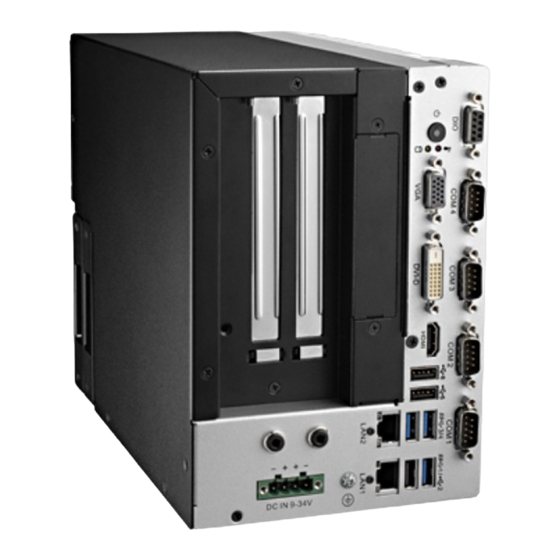
Connectors 2.3.1 ARK-3405 External I/O Locations ARK-3405 Front IO Panel Figure 2.3 ARK-3405 Front IO connector drawing ARK-3405 Rear IO Panel Figure 2.4 ARK-3405 Rear IO connector drawing ARK-3405 User Manual... -
Page 22: Ark-3405 External I/O Connectors
2.3.2 ARK-3405 External I/O connectors 2.3.2.1 Audio Connector ARK-3405 offers stereo audio ports by two phone jack connectors of Line_Out, Mic_In. The audio chip is controlled by ALC892. Figure 2.5 Audio connector Table 2.2: Audio Connector Pin Assignments Audio Signal Name... -
Page 23: Figure 2.7 Com Connector
RS-422/485, please refer to the jumper setting pages. The BIOS setting of RS-232/ 422/485 can be found in Chapter 3.1.2.3. The RS-422/485 mode of ARK-3405 COM3~COM4 can be supported via BIOS set- ting. The setting is under Advanced BIOS Features Setup -> Super IO Configuration. -
Page 24: Figure 2.9 Power On/Off Button
2.3.2.5 Power On/Off Button ARK-3405 has a Power On/Off button with LED indicators on the front side that show On status (Green LED) and Off/Suspend status (Orange LED). The Power button supports dual functions: Soft Power -On/Off (Instant off or Delay 4 Seconds then off), and Suspend. -
Page 25: Figure 2.12Dvi-D Connector
2.3.2.8 Digital Visual Interface Connector (DVI-D) ARK-3405 offers a Digital Visual Interface connector by a D-sub 24-pin female DVI-D connector; it’s only for digital video signal. This interface supports high-speed, high resolution digital displays, with resolutions of up to 1920 x 1200. -
Page 26: Figure 2.14Usb3.0 Connector
2.3.2.10 USB3.0 Connector The USB port USB port 2, 3, 4 of ARK-3405 supports USB3.0 interface, which gives complete Plug & Play and hot swapping for up to 127 external devices. The USB interface complies with USB UHCI, Rev. 3.0. Please refer to Table. 2.10 for its pin assignments. -
Page 27: Figure 2.16Power Input Connector
BI_DC-(GHz) RX-(10/100),BI_DB-(GHz) BI_DD+(GHz) BI_DD-(GHz) 2.3.2.12 Power Input Connector ARK-3405 comes with a four-pin header that carries 9 ~ 36 VDC external power input. Figure 2.16 Power Input Connector Table 2.11: Power connector pin assignments Signal Name +9 ~ 36 V... -
Page 28: Installation
Installation 2.4.1 Memory Installation Unscrew the 4 screws on the top, and remove the top cover. Install the memory into the system. Replace the top cover and screw in the 4 screws. ARK-3405 User Manual... -
Page 29: Hdd/Ssd Installation
Unscrew 4 screws on the rear side of the system. Pull out the drawer and insert a HDD/SSD. Screw 4 screws on rear side of the drawer. Put the drawer with a HDD/SSD back into the system. Screw the side cover back on. ARK-3405 User Manual... -
Page 30: Minipcie Module
2.4.3 MiniPCIe module Unscrew 6 screws on the chassis and remove it. Unscrew 2 screws on the front bezel. ARK-3405 User Manual... - Page 31 Unscrew the screw on the motherboard and remove the front bezel with riser card. Put the miniPCIe module into the mini PCIe slot and replace the screws. Screw the front bezel with riser card back into system. Replace chassis and screws. ARK-3405 User Manual...
-
Page 32: Riser Card Installation
2.4.4 Riser Card Installation Unscrew 6 screws on the chassis and remove it. Unscrew 2 screws on the front bezel. ARK-3405 User Manual... - Page 33 Remove the screw on the mother board and remove front bezel with riser card. Unscrew 4 screws on the bracket and take off the riser card off. ARK-3405 User Manual...
-
Page 34: Sd Card Installation
Place another riser card on the bracket and fix it with screws. Fix front bezel and riser card back into the system. Replace chassis and screws. 2.4.5 SD Card Installation Unscrew the 4 screws on the top, and remove the top cover. ARK-3405 User Manual... -
Page 35: Lan Clip Installation
Insert the SD card into the system. 3. Replace the top cover and screws. 2.4.6 LAN Clip Installation Put the clip inside the gap between connector and LAN port. Fix clip on LAN port. ARK-3405 User Manual... -
Page 36: Sim Installation
Unscrew 2 screws on the front bezel. Unscrew 1 screw on mother board and remove front bezel with riser card. Install WWAN module in CN17 and replace screws. Screw front bezel and riser card back into the system. Replace chassis and screws. ARK-3405 User Manual... -
Page 37: Bios Settings
Chapter BIOS Settings... -
Page 38: Entering Setup
With the AMIBIOS Setup program, users can modify BIOS settings and control vari- ous system features. This chapter describes the basic navigation of the ARK-3405 BIOS setup screens. AMI's BIOS ROM has a built-in Setup program that allows users to modify the basic system configuration. -
Page 39: Advanced Bios Features Setup
3.1.2 Advanced BIOS Features Setup Select the Advanced tab from the ARK-3405 setup screen to enter the Advanced BIOS Setup screen. Users can select any item in the left frame of the screen, such as CPU Configuration, to go to the sub menu for that item. Users can display an Advanced BIOS Setup option by highlighting it using the <Arrow>... - Page 40 3.1.2.1 Trusted Computing Security Device Support Enables or Disables BIOS support for security device. OS will not show Security Device. TCG EFI protocol and INT1A interface will not be available. ARK-3405 User Manual...
- Page 41 OS. ACPI Sleep State Select the highest ACPI sleep state the system will enter when the SUSPEND button is pressed. Lock Legacy Resources Enables or Disables Lock of Legacy Resources ARK-3405 User Manual...
- Page 42 Set Parameters of Serial Port 1 (COMA) Serial Port 2 Configuration Set Parameters of Serial Port 2 (COMB) Serial Port 3 Configuration Set Parameters of Serial Port 3 (COMC) Serial Port 4 Configuration Set Parameters of Serial Port 4 (COMD) ARK-3405 User Manual...
- Page 43 3.1.2.4 H/W Monitor PC Health Status This page display all information about system Temperature/Voltage. Power Saving Mode Select Ite8518 Power Saving Mode. Watchdog Timer Select Watch Dog Timer Mode. ARK-3405 User Manual...
- Page 44 Wake system with Fixed Time Enable or disable System wake on alarm event. Select FixedTime, system will wake on the hr:min:sec specified. Select Dynamic Time and the system will wake on the current time + Increase minute(s) ARK-3405 User Manual...
- Page 45 3.1.2.6 Serial Port Console Redirection Console Redirection Console Redirection Enable or Disable. Legacy Console Redirection Settings ARK-3405 User Manual...
- Page 46 If bi-direction is enabled, external agents can drive PROCHOT# to throt- tle the processor. Intel Virtualization Technology When enabled, a VMM can utilize the additional hardware capabilities provided by Vanderpool Technology Power Technology Enable the power management features. ARK-3405 User Manual...
- Page 47 3.1.2.8 PPM Configuration EIST Enable/Disable Intel SpeedStep. CPU C state Report Enable/Disable CPU C state report to OS. Max CPU C-state This option controls Max C state that the processor will support. ARK-3405 User Manual...
- Page 48 Note: 100C is the Plan of Record (PDR) for all Intel Mobile processors. Passive Trip Point This value controls the temperature of the ACPI critical Trip Point - the point in which the OS will begin throttling the processor. ARK-3405 User Manual...
- Page 49 3.1.2.10 SATA Configuration STTA Controller Enable/Disable SATA Device. SATA Mode Selection Determines how SATA controller operate. SATA Interface Speed Select SATA Interface Speed, CHV A1 always with Gen1 Speed. ARK-3405 User Manual...
- Page 50 Configure Serial IRQ Mode. USB3 Clock Spread Spectrum Enable USB3 Clock Spread Spectrum feature. Display Clock Spread Spectrum Enable DISPLAY Clock Spread Spectrum feature. SATA Clock Spread Spectrum Enable SATA Clock Spread Spectrum feature. ARK-3405 User Manual...
- Page 51 Choose PCI Mode if system running under Win 7 OS; Choose ACPI Mode if system running under Win 8.1 and Win 10 OS. LPSS with GPIO Devices Support Enable/Disable GPIO ACPI Devices Support, disable it will disable all LPSS devices. ARK-3405 User Manual...
- Page 52 Address Space (Only if System Supports 64 bit PCI Decoding). Don't Reset VC-TC Mapping If system has Virtual Channels, Software can reset Traffic Class mapping through the Virtual Channels to it's default state. Setting this option to Enabled will not modify VC Resources. ARK-3405 User Manual...
- Page 53 3.1.2.14 Network Stack Configuration Network Stack Enable/Disable UEFI Network Stack. ARK-3405 User Manual...
- Page 54 Storage Controls the execution of UEFI and Legacy Storage OpROM Video Controls the execution of UEFI and Legacy Video OpROM Other PCI devices Determines OpROM execution policy for devices other than Network, Storage, or Video ARK-3405 User Manual...
- Page 55 Maximum time the device will take before it properly reports itself to the Host Controller. 'Auto' uses default value: for a Root port it is 100 ms, for a Hub port the delay is taken from Hub descriptor. ARK-3405 User Manual...
- Page 56 3.1.2.17 Security Configuration TXE HMRFPO TXE Firmware Update TXE EOP Message Send EOP message before entering OS. ARK-3405 User Manual...
-
Page 57: Chipset Configuration
3.1.3 Chipset Configuration North Bridge / South Bridge North / South Bridge Parameters. 3.1.3.1 North Bridge ARK-3405 User Manual... - Page 58 Select the IGD Turbo feature, if Auto selected, IGD Turbo will only be enabled when SOC steeping is B0 or above. – Primary Display Select which of IGD/PCI Graphics device should be Primary Display. – GFX Boost Enable/Disable GFX Boost. – PAVC Enable/Disable Protected Audio Video Control. ARK-3405 User Manual...
- Page 59 Spread Spectrum clock Enable/Disable Spread Spectrum clock. – WOPCMSZ Select a size for WOPCMSZ. – PUNIT Power Configuration Enable or disable PUNIT Power configuration. – Svid Configuration Choose the right SVID Config. Graphics Power Management Control ARK-3405 User Manual...
- Page 60 Primary IGFX Boot Display Select the Video Device which will be activated during POST.\nThis has no effect if external graphics present.\nSecondary boot display selection will appear based on your selection.\nVGA modes will be supported only on primary display ARK-3405 User Manual...
- Page 61 PCIE Wake Enable or Disable PCIE to wake the system from S5. Restore AC Power Loss Select AC power state when power is re-applied after a power failure. Serial IRQ Mode Configure Serial IRQ Mode. ARK-3405 User Manual...
- Page 62 – RTC Lock Enable or disable bytes 38h-3Fh in the upper and lower 128-byte bank of RTC RAM lockdown. – BIOS Lock Enable/Disable the BIOS Lock Enable feature. – Global SMI Lock Enable or Disable SMI lock. ARK-3405 User Manual...
- Page 63 Control Detection of the Azalia device. Disabled = Azalia will be unconditionally disabled. Enabled = Azalia will be unconditionally Enabled. – Azalia HDMI Codec Enable/Disable internal HDMI codec for Azalia – HDMI Port D Enable/Disable internal HDMI Port codec for Azalia. ARK-3405 User Manual...
- Page 64 USB Configuration – XHCI Mode Mode of operation of xHCI controller – USB2 PHY Power Gating Configure USB2 PHY Power Gating. – USB3 PHY Power Gating Configure USB3 PHY Power Gating. ARK-3405 User Manual...
- Page 65 PCI Express Configuration – PCI Express Port 1 / 3 Control the PCI Express Root Port. – Native PCIE Enable – PCI Express Native Support Enable/Disable. This feature is only available in Vista. ARK-3405 User Manual...
-
Page 66: Security
3.1.4 Security Select Security Setup from the ARK-3405 Setup main BIOS setup menu. All Security Setup options, such as password protection and virus protection are described in this section. To access the sub menu for the following items, select the item and press <Enter>:... -
Page 67: Boot
Fast Boot Enables or disables boot with initialization of a minimal set of devices required to launch active boot option. Has no effect for BBS boot options. Boot Option #1 Sets the system boot order ARK-3405 User Manual... -
Page 68: Save & Exit
This item allows you to save the changes done so far as user defaults. Restore User Defaults This item allows you to restore the user defaults to all the options. Boot Override Boot device select can override your boot priority. ARK-3405 User Manual... -
Page 69: Appendix A Watchdog Timer Sample Code
Appendix Watchdog Timer Sample Code... -
Page 70: Ec Watchdog Timer Sample Code
EC_Command_Port mov al, 57h ; Watch dog event flag. out dx,al mov dx, EC_Data_Port mov al, 04h ; Reset event. out dx,al mov dx, EC_Command_Port mov al,28h ; start WDT function. out dx,al .exit ARK-3405 User Manual... -
Page 71: Usb 3.0 Drivers Installation
Appendix USB 3.0 Drivers Installation Instruction... -
Page 72: Usb 3.0 Drivers Installation Instruction
USB 3.0 Drivers Installation Instruction For customers using Windows 7 OS, they need to install drivers to active the USB 3.0 function. Please download driver installation instructions from the Intel website. (https://downloadcenter.intel.com/download/25476/Windows-7-USB-3-0-Creator-Util- ity) ARK-3405 User Manual... - Page 73 ARK-3405 User Manual...
- Page 74 No part of this publication may be reproduced in any form or by any means, electronic, photocopying, recording or otherwise, without prior written permis- sion of the publisher. All brand and product names are trademarks or registered trademarks of their respective companies. © Advantech Co., Ltd. 2016...
Need help?
Do you have a question about the ark-3405 and is the answer not in the manual?
Questions and answers