Table of Contents
Advertisement
Quick Links
Advertisement
Table of Contents

Related Manuals for Advantech ARK-3510


Summary of Contents for Advantech ARK-3510
- Page 1 User Manual ARK-3510 Fanless Embedded Box PC...
- Page 2 English user manual included as a PDF file on the CD. Please disregard the Chinese hard copy user manual if the product is not to be sold and/or installed in China. ARK-3510 User Manual...
- Page 3 The documentation and the software included with this product are copyrighted 2010 by Advantech Co., Ltd. All rights are reserved. Advantech Co., Ltd. reserves the right to make improvements in the products described in this manual at any time without notice.
-
Page 4: Declaration Of Conformity
Because of Advantech’s high quality-control standards and rigorous testing, most of our customers never need to use our repair service. If an Advantech product is defec- tive, it will be repaired or replaced at no charge during the warranty period. For out- of-warranty repairs, you will be billed according to the cost of replacement materials, service time and freight. -
Page 5: Technical Support And Assistance
Technical Support and Assistance Visit the Advantech web site at www.advantech.com/support where you can find the latest information about the product. Contact your distributor, sales representative, or Advantech's customer service center for technical support if you need additional assistance. Please have the following information ready before you call: –... -
Page 6: Ordering Information
ADAPTER 100-240V 84W 12V 7A W/PFC 9NA0840448 FSP 1702002600 Power cable 3-pin 180 cm, USA type 1702031801 Power cable 3-pin 180 cm, UK type 1702002605 Power cable 3-pin 180 cm, Europe type 1700000237 Power cable 3-pin 180 cm, PSE ARK-3510 User Manual... -
Page 7: Safety Instructions
RESTRICTED ACCESS AREA: The equipment should only be installed in a Restricted Access Area. DISCLAIMER: This set of instructions is given according to IEC 704-1. Advan- tech disclaims all responsibility for the accuracy of any statements contained herein. ARK-3510 User Manual... - Page 8 ARK-3510 User Manual viii...
-
Page 9: Table Of Contents
Chipset ...................... 4 1.3.1 Functional Specification ..............4 1.3.2 iManager ..................5 Mechanical Specifications................. 6 1.4.1 Dimensions ................... 6 Figure 1.1 ARK-3510 Mechanical dimension drawing....6 1.4.2 Weight................... 6 Power Requirement .................. 6 1.5.1 System Power................6 1.5.2 RTC Battery .................. 6 Environment Specification................. - Page 10 3.3.12 CPU PPM Configuration ............. 43 Figure 3.17CPU PPM Configuration........... 43 Chipset....................44 Figure 3.18Chipset Setup............44 3.4.1 PCH-IO Configuration..............44 Figure 3.19PCH-IO Configuration ..........44 3.4.2 System Agent (SA) Configuration..........45 Figure 3.20System Agent (SA) Configuration ......45 ARK-3510 User Manual...
- Page 11 Figure 3.23Boot Setup Utility ............48 Security Setup..................49 Figure 3.24Password Configuration ........... 49 Save & Exit....................50 Figure 3.25Save & Exit ............... 50 Appendix A Watchdog Timer Sample Code..53 EC Watchdog Timer sample code ............54 ARK-3510 User Manual...
- Page 12 ARK-3510 User Manual...
-
Page 13: Chapter 1 General Introduction
Chapter General Introduction This chapter gives background information on ARK-2150 series. -
Page 14: Introduction
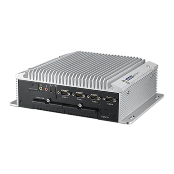
Core i rPGA high performance processor with multiple I/O interface and 2 removable 2.5" HDD drive bays. ARK-3510 offers 1 x DVI-I, 1 x DisplayPort, 1 x HDMI interface which can support independent Tri-display, 4 x USB 3.0 ports, 2 x USB 2.0 ports, 2 x Giga LAN ports, audio function, 4 x COM ports, 2 x Mini PCI sockets with SIM holders;... -
Page 15: Product Features
Storage: 2 x 2.5" removable HDD drive bays (9.5mm height), 1 x CFast card, and 2 x mSATA Expansion Interface: Supports 2 x full-size Mini-PCIe (supports mSATA and with SIM holders) Software API: Advantech iManager and SUSIAccess - Remote Device Man- agement technology 1.2.2 Display Controller: Intel HD Graphics 4000 ... -
Page 16: Chipset
Intel QM77 chip supports: Supports ACPI 4.0a Power ACPI-defined power states (processor driven C states) Management ACPI Power Management Timer SMI# generation Intel QM77 chip supports: BIOS AMI 64-Mbit EFI Flash BIOS via SPI ARK-3510 User Manual... -
Page 17: Imanager
Sequence control Supported 8-bit programmable DIO Watchdog timer Multi Level WDT (set by Advantech iManager) Programmable 1-255 sec / min Hardware monitor CPU Temperature / input Current / input Voltage Power saving Deep sleep S5 mode / Smart Fan / Back light control... -
Page 18: Mechanical Specifications
Mechanical Specifications 1.4.1 Dimensions 290[11.4] x 90[3.54] x 232[9.13] (Unit: mm [Inch]) Figure 1.1 ARK-3510 Mechanical dimension drawing 1.4.2 Weight 4.63kg (10.19lb) Power Requirement 1.5.1 System Power Minimum power input: – ARK-3510L: DC12V, 7A 1.5.2 RTC Battery Lithium 3 V/210 mAH... -
Page 19: Environment Specification
5 ~ 500 Hz, 1hr/axis, x,y,z 3 axes. 1.6.5 Shock during Operation When system is equipped with SSD/mSATA: 50G, IEC 60068-2-27, half sine, 11 ms duration. 1.6.6 Safety UL, CCC, BSMI 1.6.7 CE, FCC, CCC, BSMI ARK-3510 User Manual... - Page 20 ARK-3510 User Manual...
-
Page 21: Chapter 2 Hardware Configuration
Chapter Hardware Configuration... -
Page 22: Introduction
2.2.1 Jumper Description You may configure ARK-3510 to match the needs of your application by setting jump- ers. A jumper is a metal bridge used to close an electric circuit. It consists of two metal pins and a small metal clip (often protected by a plastic cover) that slides over the pins to connect them. -
Page 23: Jumper Location
DDR3/DDR3L setting (J1) DDR3/DDR3L Setting Part Number 1653002101 Footprint HD_2x1P_79_D Description Setting Function DDR3 Memory module (Default) (1-2) DDR3L Memory module 2.2.4.2 Auto Power On Setting (J2) Auto Power On Setting Part Number 1653002101 Footprint HD_2x1P_79_D Description Setting Function ARK-3510 User Manual... - Page 24 COM3 RS232 (Default) (3-5)*(4-6) COM3 RS422/485 2.2.4.5 COM4 RS232/422/485 setting (J5) * Please check J3/J7 for COM4 RS232/422/485 setting as well COM4 RS232/422/485 Setting Part Number 1653003260 Footprint HD_3x2P_79 Description Setting Function (1-3)*(2-4) COM4 RS232 (Default) (3-5)*(4-6) COM4 RS422/485 ARK-3510 User Manual...
- Page 25 * Please check J4/J6 for COM3 RS232/422/485 setting as well COM3 RS232/422/485 Setting Part Number 1653003260 Footprint HD_3x2P_79 Description Setting Function (1-2) COM3 RS232 (Default) (3-4) COM3 RS485 (5-6) COM3 RS422 2.2.4.9 Clear CMOS (J9) Clear CMOS Part Number 1653003101 ARK-3510 User Manual...
-
Page 26: Switch
(OFF)1*(OFF)2 NO TERMINATION (Default) (OFF)1*(ON)3 TERMINATION PU (OFF)2*(ON)4 TERMINATION PD 2.3.1.2 COM3 RS485 Termination PU/PD COM3 RS485 Termination PU/PD Part Number 1600003089-01 Footprint SW_2x2P_100_198x378 Description Setting Function (OFF)1*(OFF)2 NO TERMINATION (Default) (OFF)1*(ON)3 TERMINATION PU (OFF)2*(ON)4 TERMINATION PD ARK-3510 User Manual... - Page 27 Part Number 1600003089-01 Footprint SW_2x2P_100_198x378 Description Setting Function (OFF)1*(ON)3 AUTO-DETECTION (Default) (OFF)1*(OFF)2 PCIE CARD (OFF)2*(ON)4 mSATA 2.3.1.4 PCIE/mSATA Selection PCIE/mSATA Selection Part Number 1600003089-01 Footprint SW_2x2P_100_198x378 Description Setting Function (OFF)1*(ON)3 AUTO-DETECTION (Default) (OFF)1*(OFF)2 PCIE CARD (OFF)2*(ON)4 mSATA ARK-3510 User Manual...
-
Page 28: Connectors
2.4.2 ARK-3510 Front I/O connectors 2.4.2.1 Audio Connector ARK-3510 offers stereo audio ports by three phone jack connectors of Line_Out, Line_In, Mic_In. The audio chip is controlled by ALC892, and it’s compliant with Aza- lea standard. Figure 2.4 Audio connector Table 2.3: Audio Connector Pin Assignments... -
Page 29: Figure 2.5 Usb2.0 Connector
2.4.2.3 COM Connector ARK-3510 provides up to four D-sub 9-pin connectors, which offers RS-232/422/485 serial communication interface ports. Default setting is RS-232, if you want to use RS-422/485, you just need to change BIOS setting. The BIOS setting of RS-232/422/ 485 can be found in Chapter 3.3.8 &... -
Page 30: Ark-3510 Rear I/O Connectors
2.4.3.1 Power On/Off Button ARK-3510 has a Power On/Off button with LED indicators on the front side that show On status (Green LED) and Off/Suspend status (Orange LED). The Power button supports dual functions: Soft Power -On/Off (Instant off or Delay 4 Seconds then off), and Suspend. -
Page 31: Figure 2.10Displayport Connector
DP_PWR 2.4.3.5 Digital Visual Interface Connector (DVI-I) The ARK-3510 offers an integrated D-sub 24-pin female DVI-I Digital Visual Interface connector; it carries integrated analog and digital video signals. This supports high- speed, high-resolution digital displays and traditional analog displays. Figure 2.11 DVI-I Connector Table 2.7: DVI-I Connector pin assignments... -
Page 32: Figure 2.12Hdmi Receptacle Connector
2.4.3.7 USB3.0 Connector The USB port USB port 1, 2, 3, 4 of ARK-3510 supports USB 3.0 interface, which gives complete Plug & Play and hot swapping for up to 127 external devices. The USB interface complies with USB UHCI, Rev. 3.0 compliant. Please refer to Table. -
Page 33: Table 2.9: Usb 3.0 Connector
2.4.3.8 Ethernet Connector (LAN) ARK-3510 is equipped with up to four Ethernet controllers that are fully compliant with IEEE 802.3u 10/100/1000 Mbps CSMA/CD standards. The Ethernet port pro- vides a standard RJ-45 jack connector with LED indicators on the front side to show its Active/Link status (Green LED) and Speed status (Yellow LED). -
Page 34: Installation
Install the CPU on the socket, and screw to the lock on the socket Unscrew 2 screws on memory bracket Install the memory into the system. Screw the 2 screws back onto the memory bracket with the M/B Recover the top chassis ARK-3510 User Manual... -
Page 35: Cfast / Sim Installation
Put the HDD thermal pad on the drive bay and screw the HDD/SSD on the removable drive bay through 4 screws on the heatsink bottom Push the removable drive bay back to the system Screw 1 screw on the removable bay with the front panel ARK-3510 User Manual... -
Page 36: Minipcie Module / Internal Sim Holder Installation
MiniPCIe module / Internal SIM holder Installation Unscrew 4 screws on the bottom cover, and remove the bottom cover. Install the miniPCIe module (CN38) and screw 2 screws on the module. (This module is connected to front panel SIM holder). ARK-3510 User Manual... - Page 37 ARK-3510 User Manual...
-
Page 38: Cpu Thermal Grease Pad
Push back the removable drive bays, and screw the 2 screws on the front panel. 2.5.5 CPU thermal Grease Pad CPU thermal grease pad is one of the key components of ARK-3510 thermal design. Always use the grease pad provided by Advantech. The P/N of the grease pad is: Part Number Description 1990020828N001 Thermal-Pad D27*0.25 K=3 TP HW-PCM45Fφ27*0.25... -
Page 39: Memory Thermal Pad
2.5.6 Memory thermal Pad The memory thermal pad is one of the key components of ARK-3510’s thermal design. Always use the thermal pad provided by Advantech. The P/N of the thermal pad is: Part Number Description 1990018953T001 Thermal-Pad 59X16X1.0mm K=1.2 TP Fujipoly XR-Hl To ensure the best thermal performance, please always make sure the memory ther- mal pad is well taped between the memory bracket and memory module. - Page 40 ARK-3510 User Manual...
-
Page 41: Chapter 3 Bios Settings
Chapter BIOS Settings... -
Page 42: Entering Setup
AMIBIOS has been integrated into many motherboards for over a decade. With the AMIBIOS Setup program, users can modify BIOS settings and control various sys- tem features. This chapter describes the basic navigation of the ARK-3510 BIOS setup screens. Figure 3.1 Setup program initial screen AMI's BIOS ROM has a built-in Setup program that allows users to modify the basic system configuration. -
Page 43: System Time / System Date
MM/DD/YY format. The time must be entered in HH:MM:SS format. Advanced BIOS Features Setup Select the Advanced tab from the ARK-3510 setup screen to enter the Advanced BIOS Setup screen. Users can select any item in the left frame of the screen, such as CPU Configuration, to go to the sub menu for that item. -
Page 44: Acpi Settings
Figure 3.3 Advanced BIOS features setup screen 3.3.1 ACPI Settings Figure 3.4 ACPI Setting Enable ACPI Auto Configuration This item allows users to enable or disable BIOS ACPI auto configuration. Enable Hibernation This item allows users to enable or disable hibernation. ARK-3510 User Manual... -
Page 45: Cpu Configuration
This item allows users to enable or disable the intel virtualization technology. Hardware Prefetcher This item allows users to enable or disable the hardware prefetcher feature. Adjacent Cache Line Prefetch This item allows users to enable or disable the adjacent cache line prefetch feature. ARK-3510 User Manual... -
Page 46: Sata Configuration
Figure 3.6 SATA Configuration: IDE Mode (Default) SATA Controller(s) This item allows users to enable or disable the SATA controller(s). SATA Mode Selection This item allows users to select mode of SATA controller(s). Figure 3.7 SATA Configuration: AHCI Mode ARK-3510 User Manual... -
Page 47: Pch-Fw Configuration
Figure 3.8 SATA Configuration: RAID Mode RAID Mode Selection This item allows users to select mode of RAID function (Support 0, 1, 5, 10). 3.3.4 PCH-FW Configuration Figure 3.9 PCH-FW Configuration ARK-3510 User Manual... -
Page 48: Amt Configuration
This item allows users to un-configure ME without password. Amt Wait Timer Set timer to wait before sending ASF_GET_BOOT_OPTIONS. Disable ME This item allows users to enable or disable Intel ME. This item allows users to enable or disable Alert Specification Format. ARK-3510 User Manual... -
Page 49: Usb Configuration
USB3.0 Support This item allows users to enable or disable USB3.0 support. XHCI Hand-Off This is a workaround for the OS without XHCI hand-off support. The XHCI ownership change should claim by XHCI driver. ARK-3510 User Manual... -
Page 50: Smart Settings
Hub descriptor. 2.0 Flash Disk 5.00 This is a Mass storage device emulation type. 3.3.7 SMART Settings Figure 3.12 SMART Settings SMART Self Test This item allows users to enable or disable SMART Self Test. ARK-3510 User Manual... -
Page 51: It8760 Super Io Configuration
This item allows users to select Serial Port mode. Serial interface This item allows users to select RS-232/422/485. Default by RS-232. 3.3.8.4 Serial Port 4 Configuration Serial Port This item allows users to enable or disable COM4. ARK-3510 User Manual... -
Page 52: Platform Misc Configuration
This item allows users to select Serial Port mode. Serial interface This item allows users to select RS-232/422/485. Default by RS-232. 3.3.9 Platform Misc Configuration Figure 3.14 Platform Misc Configuration Native PCIE Enable This item allows users to enable or disable native PCIE support feature. ARK-3510 User Manual... -
Page 53: Embedded Controller Configuration
This item allows users to set backlight Function. EC Watch Dog Function This item allows users to set EC Watch Dog Function. USB SUS Power Support This item allows users to set the standby power for USB5, USB6 under SUS mode. ARK-3510 User Manual... -
Page 54: Serial Port Console Redirection
Figure 3.16 Serial Port Console Redirection Console Redirection This item allows users to enable or disable console redirection for Microsoft Windows Emergency Management Services (EMS). Console Redirection This item allows users to configuration console redirection detail settings. ARK-3510 User Manual... -
Page 55: Cpu Ppm Configuration
This item allows users to enable or disable CPU C-state support. Config TDP LOCK This item allows users to enable or disable Config TDP LOCK. ACPI T State This item allows users to enable or disable ACPI T State. ARK-3510 User Manual... -
Page 56: Chipset
Chipset Select the Chipset tab from the ARK-3510 setup screen to enter the Chipset BIOS Setup screen. You can display a Chipset BIOS Setup option by highlighting it using the <Arrow> keys. All Plug and Play BIOS Setup options are described in this sec- tion. -
Page 57: System Agent (Sa) Configuration
SLP_S4 Assertion Width This item allows users to set a delay of sorts. Restore AC Power Loss This item allows users to select off, on and last state. 3.4.2 System Agent (SA) Configuration Figure 3.20 System Agent (SA) Configuration ARK-3510 User Manual... -
Page 58: Figure 3.21Intel Igfx Configuration
This item allows users to select DVMT total memory size. Gfx Low Power Mode This item allows users to enable or disable IGD low power mode. Graphics Performance Analyzers This item allows users to enable or disable Graphics Performance Analyzers ARK-3510 User Manual... -
Page 59: Figure 3.22Lcd Control
LCD Control Figure 3.22 LCD Control Primary IGFX Boot Display Select boot display device at post stage. Secondary IGFX Boot Display Select boot display device at post stage. Active DP Select DP display device at post stage. ARK-3510 User Manual... -
Page 60: Boot Settings
If this option is set to Disabled, the BIOS displays normal POST messages. If Enabled, an OEM Logo is shown instead of POST messages. Option ROM Message Set display mode for option ROM. INT19 Trap Response This item allows option ROMs to trap interrupt 19. ARK-3510 User Manual... -
Page 61: Security Setup
Security Setup Figure 3.24 Password Configuration Select Security Setup from the ARK-3510 Setup main BIOS setup menu. All Security Setup options, such as password protection is described in this section. To access the sub menu for the following items, select the item and press <Enter>: Change Administrator / User Password: Select this option and press <ENTER>... -
Page 62: Save & Exit
Restore Defaults The ARK-3510 automatically configures all setup items to optimal settings when users select this option. Optimal Defaults are designed for maximum system perfor- mance, but may not work best for all computer applications. In particular, do not use the Optimal Defaults if the user’s computer is experiencing system configuration... - Page 63 Save User Defaults When users have completed system configuration, select this option to save changes as user defaults without exit BIOS setup menu. Restore User Defaults The users can select this option to restore user defaults. ARK-3510 User Manual...
- Page 64 ARK-3510 User Manual...
-
Page 65: Appendix A Watchdog Timer Sample Code
Appendix Watchdog Timer Sample Code... -
Page 66: Ec Watchdog Timer Sample Code
EC_Command_Port mov al, 57h ; Watch dog event flag. out dx,al mov dx, EC_Data_Port mov al, 04h ; Reset event. out dx,al mov dx, EC_Command_Port mov al,28h ; start WDT function. out dx,al .exit ARK-3510 User Manual... - Page 67 ARK-3510 User Manual...
- Page 68 No part of this publication may be reproduced in any form or by any means, electronic, photocopying, recording or otherwise, without prior written permis- sion of the publisher. All brand and product names are trademarks or registered trademarks of their respective companies. © Advantech Co., Ltd. 2013...
Need help?
Do you have a question about the ARK-3510 and is the answer not in the manual?
Questions and answers