Table of Contents
Advertisement
Advertisement
Table of Contents

Related Manuals for Siemens simatic hmi op7


Summary of Contents for Siemens simatic hmi op7
- Page 1 Preface, Contents Part I Introduction SIMATIC HMI Part II Basic Functions OP7, OP17 Operator Panel Part III Expanded, Configurable Functions Equipment Manual Part IV Commissioning and Description of Devices Part V Appendix Glossary, Index 6AV3991–1AE05–1AB0 Release 04/99...
- Page 2 Trademarks SIMATIC is a registered trademark of Siemens AG. Some of the other designations used in these documents are also registered trademarks; the owner’s rights may be violated if they are used be third parties for their own purposes.
- Page 3 Preface Guide through the The “OP7, OP17 Operator Panel” equipment manual is divided into five manual parts: Part Chapter Contents 1 – 2 Overview of the OPs and their range of func- tions. 3 – 10 Step-by-step instructions on how you control the OPs with the standard screens.
- Page 4 Technical revision V5.01 or higher Other support In the case of technical queries, please contact your local Siemens in the sub- sidiaries and branches responsible for your area. Refer to Appendix F of this equipment manual for a list of addresses.
- Page 5 SIMATIC Customer Support offers comprehensive additional information concerning SIMATIC products through its Online services as follows: Up–to–date general information is provided – in Internet under http://www.ad.siemens.de/simatic – via Fax-Polling under 08765-93 02 77 95 00 Up–to–date product information and downloads for practical use can be found: –...
- Page 6 Preface Equipment Manual OP7, OP17 Release 04/99...
-
Page 7: Table Of Contents
Contents Part I Introduction Product Description ........... . . Configuration and process control phases . - Page 8 Messages ............. . . Message types .
- Page 9 Part III Expanded, Configurable Functions Process-Dependent Operator Guidance ........11-1 11.1 Branching by Means of Soft Keys and Function Keys...
-
Page 10: Release
..........Siemens Worldwide . -
Page 11: Functionality
Product Description Part I Introduction Functionality... - Page 12 Equipment Manual OP7, OP17 Release 04/99...
-
Page 13: Product Description
Product Description Applications of Operator Panels OP7 and OP17 allow operating states, current process values OP7 and OP17 and malfunctions of a connected PLC to be visualized. In addition, inputs can be made on the OP which can be written directly to the PLC. Some functions relating to machine diagnostics can also be executed on the Operator Panel. - Page 14 Figure 1-1 Configuration and Process Control Phase Static and variable Text which is required to be displayed on the OP has first to be created on the text components PC/PU with ProTool and then transferred to the OP. If, for example, text for display is required to comprise static and variable components, the tags have to be configured and the static text for explaining the tags has to be entered - for example:...
-
Page 15: Visualizing And Controlling Processes
Visualizing and controlling processes Display and The basic functions of an OP consist in displaying process states and in con- control functions trolling the process. The following display and control functions can be con- figured on Operator Panels OP7 and OP17: screens event messages alarm messages... - Page 16 Alarm messages Alarm messages show, in contrast to event messages, critical machine states dur ing production operations. Due to their urgency, they have to be acknowl- edged before any other action is possible. Alarm messages may contain process values. Process values are displayed either numerically - for example Motor speed 4500 or symbolically - for example...
- Page 17 Multilinguality Message text, screens, help text and system messages may be displayed in several languages. Up to three of the languages listed below can be loaded simultaneously on the same OP and presented to the operator for selection on line: German English French...
-
Page 18: Design Of Operator Panel Op7
Design of Operator Panel OP7 OP7 versions The OP7 has a plastic housing with a touch-sensitive front and is therefore suitable for ungrounded installation. The coloring of the front foil conforms with machinery directive EN 60204. The OP7 is available in the following versions: OP7/PP, OP7/DP and OP7/DP-12. -
Page 19: Functions
High-contrast LC display with LED back-lighting. Display of up to 4 lines each having a maximum length of 20 characters; the height of the characters is 8 mm. Function keyboard 8 keys (F1 to F4 and K1 to K4) for calling freely programmable, generally valid standard functions. -
Page 20: Design Of Operator Panel Op17
Design of Operator Panel OP17 OP17 versions The OP17 has a plastic housing with a touch-sensitive front and is therefore suitable for ungrounded installation. The coloring of the front foil conforms with machinery directive EN 60204. The OP17 is available in the following versions: OP17/PP, OP17/DP and OP17/DP-12. - Page 21 High-contrast LC display with LED back-lighting. The following displays can be configured: 4 lines each of 20 characters; height of characters is 11 mm 8 lines each of 40 characters; height of characters is 6 mm. Function keyboard 24 keys (F1 to F8 and K1 to K16) for calling freely configurable functions. The two-color LEDs (red/green) embedded in keys K1 to K16 can be driven by the PLC.
- Page 22 Equipment Manual OP7, OP17 1-10 Release 04/99...
- Page 23 Functionality table 2-1 below summarizes the range of functions of Operator Panesl OP7 and OP17. The values quo- ted are the maximum values that can be managed by the OP. Table 2-1 Functionality of OP7 and OP17 Function OP17 Event messages Number Length (characters) Display...
- Page 24 Table 2-1 Functionality of OP7 and OP17, continued Function OP17 Password protection Number of passwords Password levels 9 (1..9) Screens Number Display Print Screen entries per screen Number of fields per screen Number of fields per screen entry Recipes Number Display Print Recipe entries per recipe...
- Page 25 Table 2-1 Functionality of OP7 and OP17, continued Function OP17 Communication SIMATIC S5 – AS511 PP, DP-12 – FAP PP, DP-12 – PROFIBUS-DP up to 1.5 Mbaud DP, DP-12 – PROFIBUS-DP up to 12 Mbaud DP-12 SIMATIC S7/M7 – PPI DP, DP-12 –...
- Page 26 Equipment Manual OP7, OP17 Release 04/99...
-
Page 27: Status/Force Var With The Op
General Operation Part II Basic Functions Using the OP with Its Standard Functions Screens Password Protection Messages Recipes STATUS/FORCE VAR with the OP System Settings... - Page 28 Equipment Manual OP7, OP17 Release 04/99...
-
Page 29: General Operation
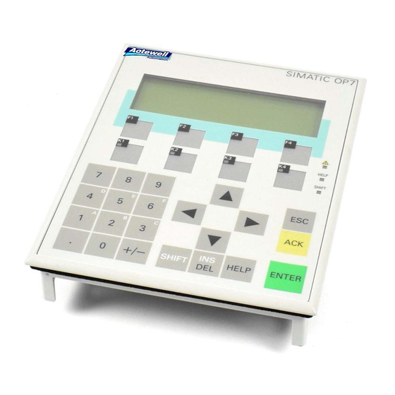
General Operation Integrated keyboard Keypads The OP7 and OP17 operator panels are controlled via the keyboard.. The keyboard of the OPs consists of two functional blocks: System keys (Numeric keypad and control keys) Function keys figure 3-1 shows the keyboard of the OP7, by way of an example. Function keys Numeric... -
Page 30: System Keys
3.1.1 System Keys Function keys for A “function key for global function assignment” always activates the same global function action on the OP or in the PLC irrespective of the screen currently displayed assignment (global meaning on the OP). Examples of such actions include: Opening a screen Starting a screen printout (Print Screen) The following keys can be assigned global functions:... - Page 31 Key functions The system keys of the OPs have the following functions: Function Purpose Shift Enable the second function of dual-assignment keys – SHIFT for example, shift of numeric keys 1 to 6 for inserting characters A to F or switching from DELETE mode to INSERT mode.
- Page 32 Function Purpose Escape The ESC key has the following functions: Cancel Cancel field inputs provided that they ENTER have not been terminated by pressing Branch backward Within a screen, you branch back to the configured cross-jump destination (by default, the last position called) and, finally, from the start screen to the message level.
- Page 33 The table below shows key combinations that can be used to activate func- combinations tions from the OP. Keys Function Purpose Adjust contrast Adjusting the contrast of the display. +/– SHIFT Scrolling in Scrolling in symbolic lists and calling of the extended SHIFT symbolic lists character set (see chapters 3.2.2 and 3.2.3).
-
Page 34: Entering Values
Entering Values General procedure In input fields, values can be entered on the OP and transferred to the PLC. To do this, proceed as follows: Step Procedure Branch, as described in section 4.3, initially to the screen you require and then to the corresponding screen entry. Using the arrow keys, select the input field you require within the screen entry. -
Page 35: Entering Numerical Values
3.2.1 Entering Numerical Values Entering via You enter numerical values character-by-character (digit-by-digit) via the system keys input keys of the system keyboard. If the field already contains a value, this entire value is deleted from the field as soon as you enter the first new char- acter. -
Page 36: Entering Alphanumeric Values
3.2.2 Entering Alphanumeric Values Mixed input of Entering alphanumeric values consists of entering both digits and letters. If digits and letters the field already contains a value, this entire value is deleted from the field as soon as you enter the first new character. Once you have begun entering a value, you can no longer quit this field until you have confirmed or aborted your input. - Page 37 Step Keys Description 2 Apply input The input becomes valid. ENTER The keypad switches back from the alphanumeric to the numeric key assignment. cancel The input cursor is deleted. input The keypad switches back from the alphanumeric to the numeric key assignment.
- Page 38 Incorrect Remedy Using keys input Character too With the keypad set to the numerical many key assignment, delete the character at the cursor position. The gap that ari- ses is closed through the characters being moved from right to left. Character too Switch to the alphanumeric key as- SHIFT...
-
Page 39: Entering Symbolic Values
3.2.3 Entering Symbolic Values Text instead of a When you enter a symbolic value, text is displayed instead of the value. If a value field has to be filled by entering symbolic values, take the value from a list of options. -
Page 40: Entering Timer Values
3.2.4 Entering Timer Values Entering via You enter timer values character-by-character (digit-by-digit) via the input system keys keys of the system keyboard. If the field already contains a value, this entire value is deleted from the field as soon as you enter the first new character. Once you have begun entering a value, you can no longer quit this field until you have confirmed or canceled your input. - Page 41 Entering a A timer can be assigned a start value by means of an input field. These val- timer value ues must be entered in a specific manner depending on the PLC being used. Proceed as follows: SIMATIC S5 and SIMATIC S7-300/400 You enter the value for the timer in seconds.
-
Page 42: Help Text
Help Text Purpose Help text is written when configuring with ProTool and provides additional information in the language set at the OP. Info text can be configured for event messages and alarm messages, screens, screen entries, input fields and dual I/O fields, recipes, recipe entries, schedulers. -
Page 43: Using The Op With Its Standard Functions
Using the OP with Its Standard Functions Loading a Once the operating voltage has been connected, you have to load a configura- configuration tion into the OP so that you can operate it. The OP is in Download mode un- til a configuration is loaded. - Page 44 Changing The operating level is changed either by the operator or automatically by the operating levels OP (figure 4-1). Change by the operator: Press key to change the operating level from message level to screen level, ENTER to change the operating level from screen level to message level. You cannot branch backward from the message level by pressing ESC.
-
Page 45: Standard Screens
Standard Screens Basic operations The standard screens contain functions that are fundamental to OP operation. with standard They include, for instance, calling and printing message buffers, editing pass- screens words and modifying parameters in online mode. Process-specific imple- mentations, such as event messages or screens for the process, are not inclu- ded. - Page 46 Figure 4-2 Screen Hierarchy of Standard Screens for the OP7 and OP17 Equipment Manual OP7, OP17 Release 04/99...
-
Page 47: Branching In Standard Screens
Branching in Standard Screens ENTER Branching to With you change from message level to screen level. At this point you screen level can control and monitor the process by means of suitable screens and stan- dard screens and perform system settings. With reference to the standard screens, a description is provided below of the procedure for branching between individual screens within the screen hierar- chy. - Page 48 Basic screen OP7 Events Alarms >> Figure 4-4 Branching at Screen Level (for OP7) Selecting screens You select a screen by pressing the soft key assigned to it during configura- tion. Use the horizontal scroll function << and >> if the required screen segment is not within the visible display area.
-
Page 49: Screens
Screens Displaying and On the OP, the process – for example, a processing machine or a mixing unit influencing the – is displayed on screens and manipulated. The screens are configured by the process on configurer for specific users. screens On screens, associated process values are acquired and provide an overview of a process or system. -
Page 50: Screen Entries
Screen Entries Displaying a Screens consist of entries. Every screen may contain up to 99 entries. Irre- screen entry spective of the configured number of lines, precisely one entry is displayed per display page on the OP. Lines which may have not been fully configured are displayed as blank lines. -
Page 51: Selecting Screens
Selecting Screens Methods of Screens can be viewed on the OP and serviced (edited) and printed. Before selecting screens this is possible, they have to be selected. A screen can readily be selected by means of soft key, function key, directory, PLC job. -
Page 52: Editing Screens
Editing Screens Procedure Screens can be manipulated, i.e. edited, by means of entries in input fields and combined I/O fields. To edit a screen, proceed as follows: Step Procedure Select the screen you wish to edit as described in section 5.2. The cursor jumps to the first input field. -
Page 53: Password Protection
Password Protection Access protection Password protection can be configured for function keys/soft keys and input fields in order to permit only authorized persons to work with the OP. Password Levels and Access Password When configuring with ProTool, the function keys/soft keys and input fields hierarchy are assigned hierarchically ordered password levels from 0 to 9, 0 being the lowest and 9 the highest level in the hierarchy. - Page 54 Supervisor The supervisor password is specified during configuration. The default set- password ting in the standard configuration is “100”. This setting can be changed on the OP. Format The password must be a minimum of 3 and a maximum of 8 characters long. It can be made up of digits and the characters A to F.
-
Page 55: Logging-In And Logging-Out On The Op (Login/Logout)
Logging-in and logging-out on the OP (LOGIN/LOGOUT) Login You can log into the OP via the standard screen Password processing Login by calling a function for which the current password level is too low.In this case, the OP automatically prompts you to enter a password. Logging in via Step Procedure... -
Page 56: Password Management
Password Management Functions The standard screen Password processing contains the following functions for managing the passwords: viewing the password list configuring passwords and assigning password levels deleting passwords changing passwords and password levels. These functions can only be called in password level 9. For this purpose, log in beforehand using the supervisor password via Password processing Login. - Page 57 pppppppp pppppppp pppppppp pppppppp Password level Password Password index Figure 6-1 Password List (Example: 4 x 20 representation) Password index The passwords are numbered consecutively with a two-digit password index. If no password is entered under a password index, the fields for the password and for password level are contain dashes.
- Page 58 Deleting a Step Procedure Result password Select the line in the password The cursor is positioned on the list, that contains the password first character of the field in entry to be deleted. which the password is to be entered. Overwrite the first character of The cursor jumps back to the the password with a zero and...
-
Page 59: Messages
Messages Overview Messages displayed on the OP indicate events and states in the control pro- cess. A message consists of at least static text and can also include tags. The following types of message are displayed on the OP: event messages, alarm messages and system messages. -
Page 60: Message Types
Message types Event and alarm Event and alarm messages are configured. Event messages indicate a status messages in the process, alarm messages indicate faults/errors. Event and alarm mes- sages are initiated by the PLC. Due to their critical nature, alarm messages have to be acknowledged. - Page 61 Standby message A sub-category of the event message is the standby message. The standby message is the event message number 0. It appears on the display when the OP is operating at the message level and event or alarm messages are not waiting.
-
Page 62: Alarm Messages
Message bit If there is a condition present in the current process for a message to be procedure issued – for example, a tag has been reached – a bit is set by the PLC ap- plication program in the data area for event and alarm messages. The OP reads the data area after a configured polling time. - Page 63 Operation To inhibit an alarm message, press the following keys simultaneously The OP acknowledges inhibition of the alarm message by means of system message $ 335. After that, this message will not be displayed until the next time the OP starts up. Inhibited alarm messages are no longer inserted into the alarm buffer from the time of inhibition, either.
-
Page 64: System Messages
7.1.3 System messages Definition System messages indicate operating states within the OP. For example, they draw your attention to maloperations or a breakdown in communication. This message type has top display priority. If a relevant fault occurs on the OP, the active event message or alarm message is removed from the display and a system message is issued in its place. -
Page 65: Displaying Messages
Displaying Messages Display Event and alarm messages are always output to the display at message level and are displayed according to display and message priorities. If several messages having identical display and message priorities exist si- multaneously, the most recent is displayed in all cases, for both event and alarm messages. -
Page 66: Display Sequences
7.2.1 Display Sequences Message length Event and alarm messages can be configured with up to 80 characters and displayed either separately or together. Single message With this display sequence, only one alarm message, event message or display (setting system message is shown on the display. On the OP17 four messages are ”separate”) displayed in the case of 8 x 40 representation. -
Page 67: Viewing Event And Alarm Message Text
Example The event messages (EM) and alarm messages (AM) illustrated below are queued on the OP. Message level 11:50 EM 02 12:00 EM 04 12:08 EM 07 11:54 AM 01 11:55 AM 05 12:01 AM 08 7.2.3 Viewing Event and Alarm Message Text Viewing Messages Irrespective of the current contents of the event or alarm buffer, all config- ured event and alarm message text can be shown on the OP. -
Page 68: Message Buffers
Message Buffers Purpose Messages displayed on the OP are written to the message buffer concerned. The message buffers can be called to view message history by means of standard screens. The times of occurrence, acknowledgment and departure are displayed in chronological order for all messages. - Page 69 Cursor keys You can use the cursor keys to select and deselect the message texts of a mes- sage and to scroll through the message list. Result Displays the message text for the message selected. Deselects the message text and returns to the message list.
-
Page 70: Deleting Messages
Deleting Messages Purpose All message events for event and alarm messages are automatically stored in the event message buffer or alarm message buffer respectively. Each of these buffers has space for up to 256 events. To prevent a buffer overflow, event and alarm messages must be deleted from their buffers. -
Page 71: Deleting Alarm And Event Messages Via Standard Screens
7.4.2 Deleting alarm and event messages via standard screens Procedure Standard screens can be used to delete all (not individual) acknowledged and departed alarm messages all (not individual) arrived and departed event messages. To delete event and alarm messages, proceed as follows: Step Procedure Depending on the type of message you want to delete, choose... -
Page 72: Printing Messages
Printing Messages How to print out You can print alarm and event messages as a direct message log (refer to section 7.5.1), as a full printout of the message buffer (refer to section 7.5.2), upon buffer overflow (refer to section 7.4.1). 7.5.1 Direct Message Logging Print time... -
Page 73: Printing The Message Buffer
7.5.2 Printing the Message Buffer Sequence Messages from the alarm or event buffers, but not the system buffer, can be printed chronological, all messages contained in the buffer of the message type concerned are printed in the order in which they are contained in the buffer together, all messages contained in the buffer of the type of message concerned are printed in ascending message number order. - Page 74 Equipment Manual OP7, OP17 7-16 Release 04/99...
-
Page 75: Recipes
Recipes Purpose Recipes are combinations of tags for a certain purpose. The purpose of recipes is to transfer data together to the PLC. This involves synchronization between the OP and PLC. Data records When configuring you define not only the recipe but the data structure too. The structure is assigned data at the OP. - Page 76 Components of a A recipe consists of a series of recipe entries. Each entry contains a maxi- recipe mum of one input field (i.e., tag). Depending on the configuration, either direct or symbolic value input can be used in an input field. The recipe called Mixture could be set up from the following entries.
- Page 77 Standard screen The standard screen Records offers you the following functions: for data records Record Edit: Creating, editing and deleting data records. Record Print: Printing out data records on a printer. Record Transfer: Transferring data records from the OP to the PLC or from the PLC to the Directory for Recipes are combined into a recipe directory which can be used to indicate recipes...
-
Page 78: Creating And Editing Data Records
Creating and Editing Data Records Default The OP automatically creates a data record with the number 1 and the name ”data record” for each recipe. All values of the data records are preset with 0. You can edit this data record. To create more data records, either copy this data record (see chapter 8.2), or edit this data record and save it under a different name. - Page 79 As long as you have not confirmed an input value, you can terminate editing with ESC. The old value is then displayed again. Storing a changed To save a changed data record as a new data record, do not overwrite the data record as a called data record when exiting the input screen.
-
Page 80: Copying Data Records
Copying Data Records Overview There are two ways to copy a data record. You can call an existing data record for editing, and save it unchanged under a new number and, if necessary, under a new name. Then make your changes. Save an existing record via data record transfer under a new number and, if necessary, under a new name. -
Page 81: Transferring Data Records
Transferring Data Records Overview A transfer screen offering the following functions is available for transferring data records. Before a changed or newly set up data record in a recipe can become effective in the PLC, it must first be transferred via data record transfer to the PLC. - Page 82 Example of entering source and destination: PLC Transfer Source Destina- Description tion Source data record 11 is an existing data record on the OP and is to become the active data record on the PLC (destination). OP Transfer Source Destina- Description tion The source data record 0 is the active data record on the PLC...
- Page 83 Using the transfer Proceed as follows to transfer a data record. screen Step Procedure Select the standard screen Record Transfer. Select the recipe in the recipe directory Position the cursor on the Source field in the transfer screen. Depending on the direction of transfer desired, enter the appropriate source number (see examples), and confirm.
-
Page 84: Deleting Data Records
Deleting Data Records Note Data records of a recipe can be deleted from the data record directory. These data records are then no longer available for the recipe. When a data record which is active in the PLC is deleted from the directory of the OP, this data record still continues to be active in the PLC. - Page 85 STATUS/FORCE VAR with the OP Purpose The operator panel offers you the two functions STATUS VARand FORCE VAR which enable you to display and modify operand values from the con- nected SIMATIC S5/S7/M7 PLC via standard screens. In online mode, this means that PLC operands can be edited directly on the OP without having to connect a programming unit/PC to the PLC.
- Page 86 FORCE VAR You call FORCE VAR by means of the standard screen ForceVAR. Following the call, the operand list is displayed. Depending on the display, an operand is displayed on either one or two lines. Figure 9-1 shows the display for the SIMATIC S5 on the OP17 (8 x 40 repre- sentation).
- Page 87 Displaying PLC Step Procedure operands Press SHIFT Select the data type you wish to have displayed using the cursor keys. Press ENTER The corresponding data format is set automatically in the format field. Shift Lock mode is de-activated at the same time. Going to numbers Step Procedure...
- Page 88 Entering values Within the lines and value fields, the cursor can be moved horizontally. A total of ten lines can be assigned. Confirm inputs by pressing ENTER The values of the operands you select are displayed in the value field in the specified format.
- Page 89 Operand Data type SIMATIC S5 (Output only) (Output only SIMATIC S7-200 CHAR WORD WORD REAL BOOL BOOL STRING TIMER COUNTER SIMATIC S7-300/400 DB, M CHAR WORD REAL BOOL STRING TIMER COUNTER E, PE, A, PA CHAR WORD REAL BOOL STRING TIMER COUNTER Equipment Manual OP7, OP17...
- Page 90 Equipment Manual OP7, OP17 Release 04/99...
-
Page 91: System Settings
System Settings In this chapter This chapter informs you of functions that can be triggered by standard screens to perform system settings. They include: Selecting a language, Modifying parameters for OP interfaces, printers, message display, date and time, Adjusting display contrast, Setting OP mode. -
Page 92: Modifying Parameters In Online Mode
10.2 Modifying Parameters in Online Mode Modifying inter- The parameters set as default parameters for the OP interfaces during confi- face parameters guration can be modified by means of standard screens. To do this, proceed as follows: Step Procedure Depending on the OP you are using, choose one of the standard screens marked System settings Scroll through the parameter list on the display using the arrow keys to the parameter you require. - Page 93 Setting first/last To define whether the oldest or the most recent alarm messages (for first/last message display message refer to section 7.2) is displayed when several are waiting to be displayed, proceed as follows: Step Procedure Choose the standard screen System settings DispMsg.
-
Page 94: Adjusting Contrast
10.3 Adjusting Contrast Settings On the OP7 and OP17, you can adjust the contrast of the LCD. The display contrast can be adjusted by means of direct adjustment or a standard screen. Direct contrast The display contrast of the LCD can be adjusted at all times in normal mode adjustment by means of direct control: Step... -
Page 95: Setting Op Modes
10.4 Setting OP Modes Modes You can set the following OP modes by means of standard screens: Online, Offline, Download and Loop-Through (OP17 only). Online This the default operating mode for unrestricted control and visualization of the process. In Online mode, there is a logical link between the OP and the PLC, or the OP tries to establish a link. - Page 96 Equipment Manual OP7, OP17 10-6 Release 04/99...
-
Page 97: Schedulers (Op17 Only)
Process-Dependent Operator Guidance Part III Expanded, Configurable Functions Schedulers (OP17 only) Controlling the OP from the PLC... - Page 98 Equipment Manual OP7, OP17 10-8 Release 04/99...
-
Page 99: Process-Dependent Operator Guidance
Process-Dependent Operator Guidance Situation-specific Different action is normally required or allowed in different operating process control situations. To support changing requirements during process control, you can configure the following measures, which provide the operator with situation- specific purposeful help: screen-dependent soft keys, global function keys and user-defined screen hierarchies. - Page 100 Assignments of You can assign the following functions to function keys and soft keys: function keys and branch to message level, soft keys select screen, initiate a print job, display directory, modify parameters in online mode. Password level A password level may be assigned to a function key or a soft key. This means assignment that you can make functions, such as ”Modify parameters in online mode”, available only to authorized persons.
-
Page 101: Self-Defined Screen Hierarchy
11.2 Self-Defined Screen Hierarchy Defining the The screen hierarchy can be adapted to system-specific requirements and be screen hierarchy modified either in part or in whole. Screens can be removed or added. Screens can be linked together in random order. The design, sequence of the link, inclusion in the screen directory and the relevant cross-jump destina- tions are defined during configuration with ProTool. - Page 102 Example The OP is used to operate and monitor a system for producing and bottling different fruit juices. The system consists basically of a mixing unit and a bottling machine. Mixing unit The ingredients for the fruit juices are contained in three tanks. Depending on the juice that you wish to manufacture, ingredients are mixed in certain ra- tios.
- Page 103 If you press the ”Tank2” soft key, the entry displayed in figure 11-4 appears. This entry contains static text and two output fields (Tank Contents and Set Temperature) as well as an input field (Valve Position) The position of the tank valve can be set in the input field by means of a symbolic value input –...
- Page 104 Equipment Manual OP7, OP17 11-6 Release 04/99...
-
Page 105: Release
Schedulers (OP17 only) Definition Depending on the configuration, you can specify so-called schedulers for the OP17. A scheduler is a regularly recurring point in time (i.e., hourly, daily, weekly, annually) at which a certain function is to be executed. Up to 48 schedulers and their corresponding functions can be configured A scheduler is contained in a screen entry where it can be entered, changed or deactivated when the screen is displayed. - Page 106 Functions The following functions can be called via schedulers. Print alarm message buffer (chronologically or together) Print event message buffer (chronologically or together) Select screen Print screen Print data record Displaying The schedulers have already been preset via configuration. A scheduler can schedulers be changed or deactivated via input fields in a screen entry.
- Page 107 Controlling the OP from the PLC Common data The OP and the application program communicate with each other by alter- areas nately reading from and writing to the data areas in the memory of the PLC. Thus the PLC and the OP can make each other execute different actions by evaluating data areas.
- Page 108 Function keyboard With pressing a function key, it can be used to set a bit on the PLC, where it image is evaluated by the application program. For this, you must have created the necessary data area on the PLC for the keyboard image and have specified the appropriate area pointer in the confi- guration for assigning the key to a bit.
-
Page 109: Device Description
Installation Part IV Commissioning and Description of Devices Commissioning Device Description... - Page 110 Equipment Manual OP7, OP17 13-4 Release 04/99...
-
Page 111: Installation
Installation Mounting location Operator Panels OP7 and OP17 are suitable for fitting into control cabinets and conditions and consoles. Before you install an OP, you must cut out a section of the front panel (moun- ting cutout) (see chapter 16). The front panel must not be thicker than 6 mm. No other drilled holes are required for mounting. -
Page 112: Mechanical Installation
14.1 Mechanical Installation Installing the OP Step Procedure Push the enclosed gasket from the rear over the housing and insert the OP from the front in the prepared mounting cutout. Take suitable measures to prevent the OP from falling out of the front panel before it is finally fixed in position. -
Page 113: Electrical Installation
Screw down or lock all plug connections. Do not install signal lines in the same cable ducts as high voltage lines. Siemens AG accepts no responsibility whatsoever for malfunctions and damage arising from the use of self-made cables or cables from other manufacturers. -
Page 114: Connecting The Power Supply
14.2.1 Connecting the Power Supply Terminal Block There is a two-pin screw-type terminal on the lower side of the OP housing for connecting the power supply. The screw-type terminal is designed for cables having a cross-section not larger than 2.5 mm . -
Page 115: Connecting A Configuration Computer
COM2 (9-pin) 1) Not with OP7-DP and OP17 2) Do not use the converter cable from Siemens for connecting via TTY, since OP7-DP and OP17 do not supply 20 mA. Figure 14-2 Connection Configuration Scheme for Configuration Computers Equipment Manual OP7, OP17... -
Page 116: Connections To Plc
SIMATIC S7/M7 PROFIBUS-DP 1) Not with OP7-DP and OP17-DP 2) Do not use the converter cable from Siemens for connecting via TTY, since OP7-DP and OP17-DP do not supply 20 mA. 3) Any PROFIBUS bus terminal (except FSK) Figure 14-3 Connection Configuration Scheme for PLCs... - Page 117 Configuring You can configure interface IF1B using the DIP switch at the rear of OP interface IF1B versions DP and DP-12. This involves changing over the RS422 receive data and the RTS signal. By default, the RTS signal is not required by the commu- nicating peer.
-
Page 118: Loop-Through Mode (Op17 Only)
14.2.4 Loop-Through Mode (OP17 only) Connection The IF1 interface of the OP17 is optionally available for the loop-through Configuration mode of a configuration computer (PU or PC). This enables communication Scheme between the PU or PC and the PLC via the OP17. Standard cables are available for the connections in AS511 loop-through mode shown in Figure 14-4 (refer to the ST80.1 catalog). -
Page 119: Connecting A Printer
Y cable is required for simultaneous operation of a printer. The PLC and printer, in this case, are operated with physically different interfaces. For attaching Siemens printers, there are standard cables available (refer to Catalog No. ST80.1). For other printers, you have to use the cables supplied or specially manufactured ones. - Page 120 Settings The settings of parameters for the print functions, the printer interface and the printer are configured. Section 10.2 describes how you can modify the default printer parameters in Online mode. You will find the requisite printer settings in the User’s Manual for your printer.
-
Page 121: Commissioning
Commissioning Diagrammatic The commissioning guide which follows explains the different steps that representation have to be taken to commission the OP. Figure 15-1 shows the most impor- tant steps for initial commissioning, recommissioning and normal operation of the OP. Initial Commissioning Recommissioning Normal Operation No configuration/firmware... - Page 122 Before Before commissioning the OP, take note of the following: commissioning Caution With the SIMATIC S5, compression of the internal program memory of the PLC (PU ”Compress” function, integrated COMPR FB) is not al- lowed when an OP is connected. Compression modifies the absolute ad- dresses of the blocks in the program memory.
-
Page 123: Initial Commissioning
15.1 Initial commissioning Procedure Initial commissioning comprises loading the firmware required to enable the OP to function and the configuration onto the OP. You do this as follows: Step Procedure Switch on the OP’s power supply. Since a configuration has not yet been loaded at this point in time, the OP automatically switches to download mode and waits for data to be downloaded from the configuration computer (PC/PU). -
Page 124: Recommissioning
15.2 Recommissioning Procedure If you want to replace a configuration already loaded on the OP with another one, proceed as follows: Step Procedure Using a suitable standard cable, connect the configuration com- puter (PU or PC) to the interface of the OP: IF1A for OP7 IF2 for OP17 Switch on the power supply of the OP. -
Page 125: Start-Up Behavior
15.3 Start-up Behavior After the power supply has been turned on, the OP performs a Self test self test. In the test, it checks the operability of the most impor- tant device components and displays the test results. If there is not a configuration on the OP, the OP switches auto- OP starts up matically to Download mode. -
Page 126: Testing The Configuration In Offline Mode
15.4 Testing the Configuration in OFFLINE Mode Purpose In OFFLINE mode, you can test the different functions and the configura- tions downloaded from the PC or PU independently of the PLC. In OFFLINE mode, tags are not updated. Procedure Step Procedure Switch the OP to OFFLINE mode using the standard screen System settings... -
Page 127: Testing The Configuration In Conjunction With The Plc
15.5 Testing the Configuration in Conjunction with the PLC Test with PLC Once the tests in OFFLINE mode have been performed successfully, the OP connected is tested in conjunction with the PLC that you connected. This test deter- mines whether the correct data areas have been configured. Procedure Step Procedure... -
Page 128: Testing Communication Via The Profibus-Dp
15.6 Testing Communication via the PROFIBUS-DP Bus fault LED Mounted on the rear side of unit variants DP and DP-12 is a bus fault LED (figure 15-2). When the OP is connected to SIMATIC S7, this LED indicates that communication between the OP and the PLC over PROFIBUS-DP is OK by lighting up constantly. - Page 129 Device Description In this chapter This chapter describes the versions, dimension drawings and connection elements of Operator Panels OP7 and OP17. 16.1 Dimensions Mounting cutout The OP7 requires the following mounting cutout (WxH): mm x 171 Equipment Manual OP7, OP17 16-1 Release 04/99...
- Page 130 Connection The OP7 is available in versions PP, DP and DP-12. The versions differ only elements in as far as their communication options are concerned (refer to table 16-1). Figure 16-1 shows the connection elements on the underside of the OP7. IF 1A IF 1B Figure 16-1 Locations of the Connection Elements on the Underside of the OP7...
- Page 131 16.2 OP17 Dimensions Mounting cutout The OP17 requires the following mounting cutout (WxH): mm x 195 Equipment Manual OP7, OP17 16-3 Release 04/99...
- Page 132 Connection The OP17 is available in versions PP, DP and DP-12. The versions differ only elements in as far as their communication options are concerned (refer to table 16-2). Figure 16-2 shows the connection elements on the lower side of the OP17. IF 2 IF 1B IF 1A...
-
Page 133: Labeling Of The Function Keys
16.3 Labeling of the Function Keys Situation The function keys of the OP7 and OP17 are labeled as follows when deliv- on delivery ered: – OP7: F1 to F4 and K1 to K4. – OP17: F1 to F8, K1 to K8 and K9 to K16. - Page 134 Note Take note of the following points before you insert labeling strips: Labeling on strips must be smudge-proof before they can be inserted. If a keyboard overlay is soiled on the inside, it cannot be cleaned and has to be returned to the manufacturer for replacement. Protect the labeled side with transparent adhesive tape.
- Page 135 Transparent LED window Key area for labeling Figure 16-5 Dimensions of Labeling Strips for the OP7 File Together with the ProTool configuration software in the PROTOOL\ UTILITY folder the Word files SLIDE_07.DOC and SLIDE_17.DOC are supplied. The files contain formatted samples of the labeling for function keys on the OP7 and OP17.
- Page 136 Source of supply You can obtain the backup battery from the Siemens spare parts service. It is shipped ready for installation with a cable and a plug connector. Please refer to our ST80.1 catalog for the order number.
-
Page 137: Maintenance
General Please comply with the safety information that is included with the battery information and informs you how to handle and dispose of lithium batteries in the proper manner. Warning Explosion hazard! There is a danger of the lithium battery exploding if it is not handled properly. - Page 138 Equipment Manual OP7, OP17 16-10 Release 04/99...
- Page 139 Brief Description of Standard Screens Part V Appendix System Messages Technical Data Interface Assignment SIMATIC HMI Documentation Siemens Worldwide...
- Page 140 Equipment Manual OP7, OP17 P-12 Release 04/99...
- Page 141 Brief Description of Standard Screens The table below presents an overview of all the standard screens for Operating Panels OP7 and OP17. Apart from a brief comment on functions, mention is made of the requisite password level. The ”Level 1” column lists the screens that you can choose from the basic screen. These screens allow you to make different calls, which are listed under ”Level 2”.
- Page 142 Level 1 Level 2 Function Password Level Record Edit Display directories for recipes Display and edit data records Record Transfer Copy data record Transfer data record from PLC to OP Fetch data record from PLC to OP Record Print Print recipe with selected data record System settings OPMode Set OP operating modes:...
- Page 143 System Messages Error messages at The following messages indicate a hardware failure on the memory module OP startup specified: – EPROM memory failure, – RAM memory failure, – Flash memory failure Message number OP system messages can be subdivided into various categories. The information as to which category a system message belongs to is contained in the message number as indicated below.
- Page 144 During startup, set the OP to download mode, downlaod the configuration again and then restart the OP and PLC again. c) If the fault recurs, please contact your nearest Siemens representative. When doing so, please quote the number of the error that has occurred and any variables referred to in the message.
- Page 145 Mes- Cause Remedy: sage Internal error: Error message returned if nothing configured for a system message Error during data transfer in download mode. Repeat data transfer after first chek- Two variables are transferred with this message king the physical connection if ne- which contain information about the function in cessary.
- Page 146 Mes- Cause Remedy: sage Restart after change of operating mode from of- fline to online. 110, OP is in ”normal” mode. PLC has been restarted. Establishment of logical link with PLC in pro- gress. Connection with PLC is OK again following a fault.
- Page 147 Mes- Cause Remedy: sage 217, Overlapping specified/actual values. Check configuration of actual/speci- fied values in the process link. Hardware fault: relay or port could not be set. Send unit for repair. Print buffer overflow due to overload. Printout Messages have been lost. not possible.
- Page 148 Mes- Cause Remedy: sage S7 diagnostics buffer not present. The CPU has no diagnostics buffer (hardware problem). No information text available. Input is password protected. Enter password. Incorrect password entered when attempting to log in. An existing password was entered when editing Enter a different password.
- Page 149 Communication with PLC has been resumed. Status processing in progress on PU/PC. The OP can not be used while this is going on. Internal error With non-Siemens connections: data block error Network node has illegal address. Max. addresses: S7-MPI: PROFIBUS-DP:...
- Page 150 Mes- Cause Remedy: sage – The part program specified does not exist. – The record specified does not exist. – The PLC specified (FM or NC) is not ready. – The command cannot be executed in the MCU mode selected. –...
- Page 151 Mes- Cause Remedy: sage Transfer of the data record was not acknowledged Checking of data records by the user by the PLC within a certain period. at the PLC end must be carried out more quickly (< 10 s). Firmware version is different from standard FB Please contact the SIMATIC Hotline.
- Page 152 Mes- Cause Remedy: sage Information message: disk is full. Disk access error. Disk transfer error. Check the physical connection. Information message: disk is blank. Simultaneous accessing of data record by job and Repeat uncompleted accessing ope- operator. ration. The data records in the RAM for recipe no. x con- If data records are stored in the Flash tained errors and have been deleted.
- Page 153 Mes- Cause Remedy: sage The line to be output is larger than the amount of Check configuration as regards print memory reserved for it or the number of logging. control sequences is too great. Internal error Correct the data format. Incorrect data format in process link.
- Page 154 Mes- Cause Remedy: sage Configuration error: Check the configuration. If the fault is not corrected by perfor- Variable x: ming a restart, please contact the SI- 1, 4 Information text does not exist Information text ID for messages does not exist MATIC Hotline.
- Page 155 Mes- Cause Remedy: sage Missing configuration for an event message Configure event message (–> message number) fully. b ) f ll 638, Actual value field for event message has only been created symbolically. Alarm message is not configured Configure alarm message (–> mes- sage number).
- Page 156 Mes- Cause Remedy: sage On process screen: recipe setpoint or previous Change field type or remove field value configured in recipe: field is neither recipe and retransfer configuration setpoint or previous value. Invalid destination configured for return reference Change configuration and retransfer. in screen.
- Page 157 Mes- Cause Remedy: sage Configuration error. Two tags that supply infor- If you are dealing with a configura- mation about the faulty function (Tag 1) and the tion error: delete the function and re- faulty parameter (Tag 2) are transferred together configure.
- Page 158 Mes- Cause Remedy: sage Internal error Menu number invalid. Internal error Mailbox type of received message is incorrect. Internal error The setting for the maximum number of messages is too high (variable overflow). Internal error Incorrect message status when entering in stati- stics.
- Page 159 Mes- Cause Remedy: sage Internal error Transfer parameter LEDSTATUS is incorrect in RIO function “Change LED Status“ Internal error Key number can not be higher than 7/15/23 (8-key/16-key/24-key keyboard) Internal error Key number must be less than 4 as a maximum of 4 keys is possible.
- Page 160 Mes- Cause Remedy: sage Internal error Buffer type different from event or alarm message buffer. Internal error Message type different from event or alarm mes- sage buffer. Internal error Error in data structure of a buffer function screen. Internal error Error in data structure of the password function screen.
- Page 161 Mes- Cause Remedy: sage Internal error Error during communication ( messages). Internal error Error reading area pointer Error on reading from “Basic Settings General parameters“ Internal error Data record memory full Internal error Too many schedulers in transit Internal error Reset and repeat MPI download.
- Page 162 Equipment Manual OP7, OP17 B-20 Release 04/99...
-
Page 163: Technical Data
Technical Data OP17 Housing DP-12 DP-12 Overall dimensions W x H 144 mm x 180 mm x 42.5 mm 240 mm x 204 mm x 54 mm Mounting cutout B x H 135 mm x 171 mm 231 mm x 195 mm Mounting depth 38.5 mm 50 mm... - Page 164 OP17 Keyboard DP-12 DP-12 Type Touch-sensitive keyboard Number of system keys Number of LEDs 19 (16 of which two two-color) Number of function keys of which soft keys OP17 Voltage supply DP-12 DP-12 Rated voltage +24 V DC Permissible range +18 ...
- Page 165 OP17 Interfaces DP-12 DP-12 RS232 – RS422/485 – – PPI/MPI/ PROFIBUS-DP – – (up to 1.5 Mbd)/ RS422/485 PPI/MPI/ PROFIBUS-DP – – – – (up to 12 Mbd)/ RS422/485 OP17 Ambient conditions DP-12 DP-12 Operating temperature – vertical installation 0 C ... 50 C –...
- Page 166 OP17 Noise imm nit Noise immunity DP-12 DP-12 EN 50082-1 Static discharge EN 61000-4-2 class 3 (contact discharge) RF irradiation ENV 50140 class 3 Pulse modulation ENV 50204 (900 MHz 5 MHz) RF conduction ENV 50141 class 3 Burst interference EN 61000-4-4 class 3 OP17 Emitted interference...
-
Page 167: Interface Assignment
Interface Assignment Overview Table D-1 shows the interface configuration of the different OPs. Entries D-2 to D-5 refer to the corresponding pin assignments in Tables D-2 to D-5. Table D-1 Interface assignment OP7 and OP17 OP version Interface OP17 OP17 OP17 DP-12 DP-12... - Page 168 Table D-3 Pin assignment 9-pin sub-D socket General RS422 RS485 n.c. (GND) TxD (B) Data B RxD (B) +5 V (P24-In) TxD (A) Data A RxD (A) Table D-4 Pin assignment 9-pin sub-D socket General PROFIBUS-DP n.c. (GND) Data B GND (floating) +5 V (floating) (P24-In)
- Page 169 SIMATIC HMI Documentation Target groups This manual is part of the SIMATIC HMI documentation. The documentation is aimed at the following target groups: Newcomers Users Configurers Programmers Commissioning engineers How the documentation is organized The SIMATIC HMI documentation consists of the following components: User’s Guides / User’s Manuals for: –...
- Page 170 Documentation Target Group Content First Steps with ProTool Newcomers This documentation guides you step by step through the configuration of Product Brief a screen with various objects changing from one screen to another a message. This documentation is available for: OP3, OP5, OP7, OP15, OP17 OP25, OP27, OP35, OP37, TP27, TP37 Windows-based systems...
- Page 171 Documentation Target Group Content Application Example Newcomers ProTool is supplied with example configurations and the corresponding PLC programs. This documentation describes Start–up Guide how you load the examplesonto the operating unit and PLC run the examples and upgrade the connection to the PLC to suit your own spe- cific application.
- Page 172 Documentation Target Group Content Communication for Programmers Provides information on connecting Windows-based systems Windows-based Systems to the following PLCs: User’s Manual SIMATIC S5 SIMATIC S7 SIMATIC 505 Allen Bradley PLC 5/SLC 500 This documentation describes the configuration and parameters required for connecting devices to the PLC and the network user data areas used for exchanging data between operat- ing unit and PLC.
- Page 173 All cities in the Federal Republic of Germany with Siemens Sales Offices All European and non-European Siemens Companies and Representatives Siemens Sales The following table lists all Siemens Sales Offices in the Federal Republic of Offices in the Germany. Federal Republic...
- Page 174 European The following table lists all European Siemens Companies and Companies and Representatives. Representatives Austria Finland Siemens AG Österreich Siemens Oy Bregenz Espoo, Helsinki Graz France Innsbruck Siemens S.A. Linz Haguenau Salzburg Lille, Seclin Vienna Lyon, Caluire-et-Cuire Belgium Marseille Siemens S.A.
- Page 175 Italy Romania Siemens S.p.A. Siemens birou de consultatii tehnice Bari Bukarest Bologna Russia Brescia Siemens AG Casoria Florence Mosmatic Genoa Moscow Milan Siemens AG Padua Ekaterinburg Rome Slovak Republic Turin Siemens AG Luxemburg Bratislava Siemens S.A. Slovenia Luxemburg Siemens d. o. o.
- Page 176 Kiev Non-European The following table lists all non-European Siemens Companies and Companies and Representatives of Siemens AG. Representatives Africa The following table lists all Siemens Companies and Representatives of Siemens AG in Africa. Algeria Morocco Siemens Bureau d’Alger SETEL Alger Société...
- Page 177 Tunis Sudan Zaire National Electrical & Commercial Company (NECC) SOFAMATEL S.P.R.L. Khartoum Kinshasa America The following table lists all Siemens Companies and Representatives of Siemens AG in America. Argentina Canada Siemens S.A. Siemens Electric Ltd. Bahía Blanca Montreal, Québec Buenos Aires Toronto Còrdoba...
- Page 178 Venezuela México, D.F. Siemens S.A. Monterrey Caracas Puebla Valencia Nicaragua Siemens S.A. Managua Asia The following table lists all Siemens Companies and Representatives of Siemens AG in Asia. Bahrain India Transitec Gulf Siemens Limited Manama Ahmedabad Bangalore Bangladesh Bombay Siemens Bangladesh Ltd.
- Page 179 Sri Lanka Lebanon Dimo Limited Ets. F.A. Kettaneh S.A. Colombo Beirut Syria Malaysia Siemens AG, Branch (A.S.T.E.) Siemens Electrical Engineering Sdn. Bhd. Damascus Kuala Lumpur Taiwan Nepal Siemens Ltd., TELEUNION Engineering Ltd. Amatya Enterprises (Pvt.) Ltd. Kathmandu TAI Engineering Co., Ltd.
- Page 180 Abu Dhabi Tihama Tractors & Engineering Co., Ltd. Scientechnic Siemens Resident Engineers Siemens Resident Engineers Sanaa Dubai Australia The following table lists all Siemens Companies and Representatives of Siemens AG in Australia Australia New Zealand Siemens Ltd. Siemens Ltd. Adelaide Auckland...
- Page 181 Glossary Alarm message Draws attention to particularly urgent operating states; alarm messages have to be acknowledged for this reason. Area pointer Required for enabling data transfer between the OP and the PLC. It contains details of the location and size of data areas in the PLC. Arrival of a The time at which a message is initiated by the PLC or OP.
- Page 182 Event message Draws attention to specific operating states in the machine or system connected to the PLC. Fault time The time between the arrival and departure of an alarm message. Flash memory Programmable memory which can be deleted quickly and then re-written. Field ”Placeholder”...
- Page 183 Message logging Configurable printout of alarm and event messages concurrently with output on display. Normal mode OP operating mode in which messages are displayed and screens can be manipulated. Output field Field for displaying an actual value. Password To use a protected function, it is necessary to enter a Password identifying a Password level given password level.
- Page 184 Startup test Check on the status of the central processing unit and memories each time the supply voltage is applied. System message Draws attention to internal conditions on the OP and the PLC. Equipment Manual OP7, OP17 Glossary-4 Release 04/99...
- Page 185 Index Arrived message, 7-4 Arrow keys, 3-4, 5-3 Access, 6-1 AS511 Access protection, 6-1 connection, 16-2, 16-4 ACK key, 3-3, 4-2 report, 2-3 ACK-LED, 4-2 Assigning, password, 6-5 Acknowledge key, 3-3, 4-2 Assigning the, password level, 11-2 Acknowledging, alarm messages, 4-2, 7-4 Assignment Acknowledgment area, 13-2 global, 11-1...
- Page 186 Canceling, download mode, 15-4 Configuration, 1-1 Capacity, backup battery, C-2 changing, 15-4 Category, System message, B-1 computer, 14-5, 14-6, 14-8 Causes, System message, B-2 deleting, 15-4 Change of operating level, 4-2 download, 15-3, 15-4 Change over, RTS signal, 14-7 IF 1B interface, 14-7 Changing interfaces, D-1 configuration, 15-4...
- Page 187 Creating Deleting data records, 8-3 alarm message, 7-13 labeling strips, 16-6 alarm message buffer, 7-12 screen hierarchy, 11-3 configuration, 15-4 Creating an, LED image, 13-1 data record, 8-3 Creating data areas, 1-1 event message, 7-13 Critical machine state, 1-4 event message buffer, 7-12 Cross-jump destination, 3-4, 5-1 password, 6-6 Cross-jumps, 11-3...
- Page 188 Disposal, battery, 16-9 Event message text, view, 7-9 Document associated reference, 1-2 Event messages, 1-3, 4-3, 7-2 Documentation, E-1 delete, A-1 Download mode, 4-1, 10-5, 15-3, 15-5 deleting, 7-13 canceling, 15-4 display text, A-1 Downloading max. length, 2-1 configuration, 15-3 max.
- Page 189 Forced printout, 7-12, 7-14 Housing, C-1 Foreign languages, 1-5 Humidity, C-3 Front panel cutout OP17, 16-3 OP7, 16-1 Front view I/O fields, 5-2 OP17, 16-3 Identification of recipes, 8-2 OP7, 16-1 IF 1B interface Full printout, 7-14 configuring, 14-7 Function keyboard switch, 14-7 OP17, 1-9 Image, LED, 13-1...
- Page 190 Interfaces, C-3 IF 1B, 14-7 OP17, 1-9 MPI, 16-2, 16-4 OP7, 1-7 OP17, 1-9, 16-4 Technical Data, C-1 OP7, 1-7, 16-2 LED, 1-4, 11-2 PPI, 16-2, 16-4 ACK, 4-2 RS232, 1-7, 1-9 acknowledgment, 3-3 RS422, 1-7, 1-9 alarm message, unacknowledged, 4-2 RS485, 1-7, 1-9 Bus Fault, 15-8 TTY, 1-7, 1-9...
- Page 191 Login, 4-3, 6-3, A-2 Mixing station, 8-1 Logo, 7-3 Mixture, recipe, 8-1 Logout, 4-3, 6-3, A-2 Modbus report, 2-3 Loop-through mode, 10-5, 14-8, 15-7 Mode, 4-3 constraints, 14-8 Loop-through, 10-5 particularities, 14-8 Offline, 10-5 Modes, 10-5 Modify interface parameters, 10-2 screen, 5-4 Machine diagnostics, 1-1 Modify settings, 4-3...
- Page 192 Overflow alarm messages, A-1 Offline, 10-5, 15-6 event messages, A-1 Online mode, 10-5 message buffer, 7-12 Overflow warning, 7-3, 7-12 functions, overview, 2-1 message buffer, 7-12 installing, 14-2 Overheating, prevention, 14-1 start-up, 4-1 OP modes, A-2 OP17 connection elements, 16-4 description, 16-3 Panel, 14-1 design, 1-8...
- Page 193 Polarity reversal protection, 14-3 Protection Power input, C-2 against unauthorized access, 4-6 Power supply, 14-4 against unauthorized operation, 6-1 backup battery, 16-8 ProTool, 1-1 connecting, 14-4 PU, 15-3, 15-4 PU function, 4-3 address, 9-1 PU functions, 9-1 connection, 16-2, 16-4 FORCE VAR, A-2 report, 2-3 STATUS VAR, A-2...
- Page 194 RS232 Screens, 1-3, 4-3, 5-1 connection, 16-2, 16-4 directory, 1-3, 5-1 interface, 1-7, 1-9 edit, A-1 RS422 editing, 5-4 connection, 16-2, 16-4 linking, 11-3 interface, 1-7, 1-9 max. number, 2-2 RS485 print, A-1 connection, 16-2, 16-4 printing, 5-4 Interface, 1-7 selecting, 4-6, 5-3 interface, 1-9 Screw-type clamps, 14-2...
- Page 195 Size Supervisor, 6-4 labeling strips, 16-6 password, 6-2 OP17, 16-3 Suppressing, alarm messages, 7-4 OP7, 16-1 Switching on, OP, 15-3, 15-4 SLIDE.DOC, file, 16-7 Switching over Soft key, setting bits, 11-2 message logging, 7-14 Soft keys, 3-2, 4-5, 5-2, 5-3, 11-1 overflow warning, 7-12 assignment, 5-2 Symbolic...
- Page 196 Text Upgrading, battery, 1-9, 16-8 replaces value, 3-11 Using OPs, 1-1 static, 5-2 Text attributes, 14-10 Time, 10-3, 13-2 safeguarding, 16-8 Value, input, 3-6 set, A-2 Values Time response, updating data, 2-3 changing, 3-7, 3-8, 3-12 Timer, value input, 3-6, 3-12 updating, 5-2, 9-4 Title, screen, 5-1 Variable text, 1-2...