Siemens Sinamics BOP-2 Operating Instructions Manual
Basic operator panel 2.
sinamics g120
Hide thumbs
Also See for Sinamics BOP-2:
- Operating instructions manual (36 pages) ,
- Operating instructions manual (48 pages)
Table of Contents
Advertisement
Advertisement
Table of Contents

Related Manuals for Siemens Sinamics BOP-2


Summary of Contents for Siemens Sinamics BOP-2
-
Page 3: Basic Operator Panel 2 (Bop
___________________ Basic Operator Panel 2 (BOP-2) Changes in this manual Fundamental safety ___________________ instructions ___________________ Safety notes SINAMICS BOP-2 ___________________ Overview SINAMICS G Basic Operator Panel 2 (BOP-2) ___________________ Installation ___________________ Monitoring Operating Instructions ___________________ Control ___________________ Diagnostics ___________________ Parameters... - Page 4 Note the following: WARNING Siemens products may only be used for the applications described in the catalog and in the relevant technical documentation. If products and components from other manufacturers are used, these must be recommended or approved by Siemens. Proper transport, storage, installation, assembly, commissioning, operation and maintenance are required to ensure that the products operate safely and without any problems.
-
Page 5: Table Of Contents
Table of contents Changes in this manual ........................... 7 Fundamental safety instructions ......................9 General safety instructions ....................... 9 Industrial security ........................10 Safety notes ............................11 Overview............................... 13 Installation ............................19 Monitoring ............................. 21 Control ..............................23 Diagnostics ............................27 Parameters ............................ -
Page 6: Operating Instructions, 02/2016, A5E37143404B Aa
Table of contents Basic Operator Panel 2 (BOP-2) Operating Instructions, 02/2016, A5E37143404B AA... - Page 7 ● Menu structure has been updated with the new commissioning process: Overview (Page 13) Setup Menu ● SINAMICS G120 firmware update information included with links to the Siemens Industry Online Support site giving detailed information to the nature and extent of the firmware changes.
-
Page 8: Changes In This Manual
Changes in this manual Basic Operator Panel 2 (BOP-2) Operating Instructions, 02/2016, A5E37143404B AA... - Page 9 Fundamental safety instructions General safety instructions WARNING Danger to life if the safety instructions and residual risks are not observed If the safety instructions and residual risks in the associated hardware documentation are not observed, accidents involving severe injuries or death can occur. •...
-
Page 10: Fundamental Safety Instructions
Siemens recommends strongly that you regularly check for product updates. For the secure operation of Siemens products and solutions, it is necessary to take suitable preventive action (e.g. cell protection concept) and integrate each component into a holistic, state-of-the-art industrial security concept. - Page 11 Safety notes Warnings and cautions DANGER Ensuring a safe and stable state During commissioning of the Inverter, it is essential to ensure that the system is in a safe and stable state, as some commissioning processes have the potential to start the motor. Therefore it is important to secure any loads and ensure that should the motor start, no potentially dangerous conditions exist.
-
Page 12: Safety Notes
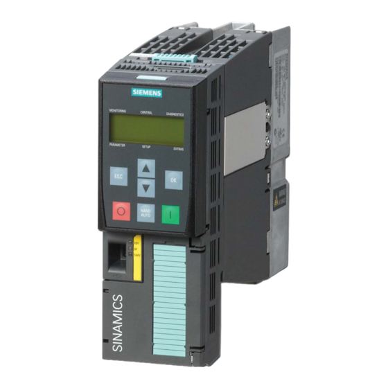
Safety notes Basic Operator Panel 2 (BOP-2) Operating Instructions, 02/2016, A5E37143404B AA... - Page 13 Overview Introduction The Basic Operator Panel 2 (BOP-2) has been designed to enhance the interface and communications capabilities of SINAMICS Inverters. The BOP-2 connects to the Inverter through an RS232 interface. The BOP-2 automatically recognize all variants of the following Control Units from the SINAMICS range: ●...
-
Page 14: Overview
Overview Layout and functions The controls, display and connections of the BOP-2 are shown in the following figure: Image 4-1 Layout of the BOP-2 Table 4- 1 Description of BOP-2 physical characteristics Item Description ① Release catch ② LCD screen ③... - Page 15 Overview The specific functions of the keys are shown in the following table. Table 4- 2 Function of the BOP-2 controls Function The OK key has the following functions: When navigating through the menus, pressing the OK key confirms selection of a menu item. •...
- Page 16 Overview Note Reaction to change between HAND and AUTO mode When changing from HAND to AUTO mode the Inverter reacts in the following manner: • If the ON signal is active, the new setpoint will become active, and the Inverter automatically ramps the motor to the new setpoint.
- Page 17 Overview Menu structure The BOP-2 is a menu-driven device and has the following basic menu structure: Image 4-2 BOP-2 Basic menu structure Basic Operator Panel 2 (BOP-2) Operating Instructions, 02/2016, A5E37143404B AA...
- Page 18 Overview Note Menu structure and functionality The actual menu structure and functionality of the BOP-2 is influenced by the following factors: • The software version and type of Control Unit to which the BOP-2 has been fitted. • The firmware and software version of the BOP-2. Basic Operator Panel 2 (BOP-2) Operating Instructions, 02/2016, A5E37143404B AA...
- Page 19 Installation Fitting the BOP-2 to the Control Unit Note BOP-2 power supply The BOP-2 has no internal power supply and derives its power directly from the Control Unit through the RS232 interface. Any cloned data stored on the BOP-2 is saved to its non- volatile memory which does not require power to retain the data.
-
Page 20: Installation
Installation Initial startup After connection and power-up the BOP-2 automatically detects the type of Control Unit then attempts to establish communications. On startup the BOP-2 will display the company name and the class of Operator Panel. The BOP-2 will then display the current software version of the Operator Panel. - Page 21 Monitoring Overview The Monitor menu allows the user to easily access a variety of screens which display the actual status of the system. The menu is selected by using the keys to move the menu bar to the required menu. Pressing will confirm the selection and display the top level menu.
-
Page 22: Monitoring
Monitoring The current output screen shows the actual Inverter current output to the motor. The frequency screen shows the actual frequency (in Hz) at which the motor is running. The RPM and current screen displays the actual rotational speed of the motor in RPM and the actual output current from the Inverter to the motor. - Page 23 Control Introduction The control menu allows the user to access the following functions of the Inverter: ● Setpoint ● Jog ● Reverse The menu is selected by using the keys to move the menu bar to the required menu. Pressing will confirm the selection and display the top level menu.
-
Page 24: Control
Control Setpoint The setpoint value determines the speed at which the motor runs as a percentage of the nominal motor speed. It should be noted that this setpoint setting is only valid while HAND mode is active. When the Inverter is set back to AUTO mode, the setpoint previously used in AUTO mode becomes the valid setpoint. - Page 25 Control Editing single digits It is possible to edit the individual digits of the setpoint screen. To enter the single digit editing mode, press until the "SP DIGIT" screen is displayed. The process of editing the individual digits is shown in the following figure: Image 7-2 Editing individual digits The Jog function, when selected, will allow the motor to be manually rotated by a pre-...
- Page 26 Control Note Reverse function When the JOG function is activate; pressing simultaneously for more than 3 seconds toggles the REVERSE function. Reverse The Reverse function, when selected, will allow the motor to be manually rotated in the reverse direction from its normal forward motion with each press of .
- Page 27 Diagnostics Diagnostic menu The Diagnostics menu allows the user to access the following function: ● Acknowledge all faults ● Faults ● History ● Status To access the Diagnostics menu, the following actions should be performed: The individual functions are described in the following text, figures and tables. Acknowledge faults When a fault condition occurs, the system is stopped by the Inverter and requires that all faults are acknowledged before restarting the system.
-
Page 28: Diagnostics
Diagnostics Image 8-2 Active faults and alarms sequence Note Dynamic fault screen If a fault occurs, the dynamic fault screen is automatically displayed. History The History option within the Diagnostics menu maintains a list of the last 64 faults that have occurred within the Inverter/motor system. - Page 29 Diagnostics Status The Status option displays the actual state of the control words and status words that are used to control and monitor various functions of the Inverter. Information regarding the control words and the status words can help diagnose problems with the Inverter. The status option displays the current state of the following control and status words: ●...
- Page 30 Diagnostics The precise details of each bit of the status screens can be found in the parameter list under the associated parameter. The exact meaning of each bit on the display is dependent on the type of Control Unit and Power Module which is being monitored. Description Associated parameter Screen example...
- Page 31 Diagnostics Description Associated parameter Screen example Status Word 2 (lower bits) r0053.0 ... 11 The screen displays the lower eight bits of Status Word 2. The individ- ual bits indicate the state of the DC brake, zero speed detection, mini- mum speed, current threshold, speed threshold, ramp-function generator and DC link threshold.
- Page 32 Diagnostics Basic Operator Panel 2 (BOP-2) Operating Instructions, 02/2016, A5E37143404B AA...
- Page 33 Parameters Parameter menu The Parameter menu allows access to view and change the parameters of the Inverter. There are two filters available to assist in the selection and searching of all the Inverter parameters, these are: ● Standard filter - this filter gives access to the most commonly used parameters for the specific type of Control Unit to which the BOP-2 is fitted.
-
Page 34: Parameters
Parameters Image 9-1 Selecting standard or export parameter filters Editing the parameters There are two methods to edit and modify parameters, these are: ● Single digit ● Scrolling Single digit editing of the parameters is accomplished by a long press of the key. - Page 35 Parameters Image 9-2 Editing parameters (single digit method) The scrolling editing is accomplished by scrolling through to the parameters until the required parameter is displayed. Press the key to confirm the parameter selection; the displayed parameter value starts to flash. Using the keys increase or decrease the parameter value.
- Page 36 Parameters Image 9-3 Editing parameters (scrolling method) Basic Operator Panel 2 (BOP-2) Operating Instructions, 02/2016, A5E37143404B AA...
- Page 37 There has been some major changes to the way that the commissioning software has been implemented and it is recommended that you read all the information given at the following links to the Siemens Industry Online Support (SIOS) site: • SINAMICS G120 Firmware V4.7 SP3 - Modified commissioning behavior Modified commissioning behavior (https://support.industry.siemens.com/cs/ww/en/view/109480663)
-
Page 38: Setup
Setup Image 10-1 Motor Plate Information, 1.5 kW The basic commissioning procedure is shown in the following figures. WARNING Failure of the commissioning process When the final step of the commissioning process is complete the operator panel screen displays "-DONE-" to indicate that the commissioning has been successful. If the commissioning process was not successfully completed, the operator panel screen displays "-FAILURE-". - Page 39 Setup Image 10-2 Standard commissioning Part 1 Basic Operator Panel 2 (BOP-2) Operating Instructions, 02/2016, A5E37143404B AA...
- Page 40 Setup Image 10-3 Standard commissioning Part 2 Basic Operator Panel 2 (BOP-2) Operating Instructions, 02/2016, A5E37143404B AA...
- Page 41 Setup Image 10-4 Standard commissioning Part 3 Basic Operator Panel 2 (BOP-2) Operating Instructions, 02/2016, A5E37143404B AA...
- Page 42 Setup Basic Operator Panel 2 (BOP-2) Operating Instructions, 02/2016, A5E37143404B AA...
- Page 43 Extras Extras menu The extras menu allows the user to perform the following functions: ● DRVRESET - reset the Inverter to the factory default settings. ● RAM ─> ROM - copies data from the Inverters RAM to the Inverters ROM. ●...
-
Page 44: Extras
Extras RAM ⇒ ROM This functions allows the data stored in the Inverter's RAM to be saved to the Inverter's ROM. The data is stored permanently in the ROM until it is overwritten by another RAM to ROM command. The symbol denotes where the screen automatically displays a new screen on the completion of a process. - Page 45 Extras From BOP This function writes parameter data stored in the BOP-2 memory to the Inverter memory. symbol denotes where the screen automatically displays a new screen on the completion of a process. Image 11-4 Extras - reading data from the BOP To card This function writes parameter data from the Inverter's memory to the memory card in the Control Unit.
- Page 46 Extras Image 11-5 Extras - writing data to the memory card Basic Operator Panel 2 (BOP-2) Operating Instructions, 02/2016, A5E37143404B AA...
- Page 47 Extras From card This function reads parameter data from the memory card in the Control Unit to the Inverter's memory. During the upload process, the user is given the option to selected a unique number between 0 and 99, which then loads the parameter set stored under that number on the memory card to the Inverter's memory.
- Page 48 Extras Basic Operator Panel 2 (BOP-2) Operating Instructions, 02/2016, A5E37143404B AA...
-
Page 49: Technical Data
Technical data BOP-2 specifications Table 12- 1 BOP-2 specifications Feature Description Protection Depending upon the Control Unit IP rating to a max. of IP55 Dimensions (H x W x D) 106.86 mm x 70 mm x 19.6 mm Net weight 0.10 Kg (0.22 lbs) Gross weight 0.17 Kg (0.37 lbs) -
Page 50: Technical Data
Technical data Basic Operator Panel 2 (BOP-2) Operating Instructions, 02/2016, A5E37143404B AA... - Page 51 Index Acknowledge faults, 27 Gross weight, 49 Active faults and alarms, 27 HAND/AUTO, 16 Control, 23 History, 28 Hand mode, 23 Humidity, 49 jog, 25 Jog, 23 reverse, 23, 26 setpoint, 23, 24 Icons, 16 Initial startup, 20 Installation, 19 fitting the BOP-2, 19 Description, 14 removing the BOP-2, 19...
-
Page 52: Index
Index frequency, 22 storage temperature, 49 output current, 22 Transport temperature, 49 overview, 21 standard commissioning RPM, 22 Macro selection, 38 voltage and current, 22 Standard commissioning, 37 voltage and RPM, 22 Maximum motor speed, 37 voltage output, 21 Standard filter, 33 Status, 29 Storage temperature, 49 Net weight, 49...
Need help?
Do you have a question about the Sinamics BOP-2 and is the answer not in the manual?
Questions and answers