Optex HX-40RAM Installation Instructions Manual
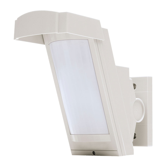
High mount outdoor detector
Hide thumbs
Also See for HX-40RAM:
- Installation instructions manual (16 pages) ,
- Installation instructions manual (12 pages)
Table of Contents
Advertisement
Quick Links
High Mount
High Mount
Outdoor Detector
Outdoor Detector
HX-40RAM
HX-40RAM
FEATURES
85°
3.0 m
12 m
CONTENTS
1-1 BEFORE YOUR OPERATION ............................... 1
1-2 PARTS IDENTIFICATION ...................................... 2
1-3 DETECTION AREA ................................................ 2
2-1 TRANSMITTER PREPARATION ........................... 3
2-2 BATTERY PREPARATION .................................... 3
3-1 MOUNTING THE BATTERY .................................. 4
AND THE BATTERY BOX............................................ 6
1
INTRODUCTION
1-1
BEFORE YOUR OPERATION
Failure to follow the instructions provided with this indication and improper handling may cause
Warning
death or serious injury.
Failure to follow the instructions provided with this indication and improper handling may cause
Caution
injury and/or property damage.
The check
mark indicates recommendation.
Warning
Do not repair or modify product
Keep the detector parallel to the ground.
Parallel
2.5 to 3.0 m
(8.2 to 10 ft.)
WIRELESS MODEL
WIRELESS MODEL
・Long battery life
・3.0 m high mount detection area (12 m)
・Unique pyro element
・Intelligent AND detection logic
The nix
Keep the product away from
the water
Consider the direction of the intruder, for the setting of the
detection area.
Tilt
INSTALLATION INSTRUCTIONS
・Dual signal processing circuit
・Vegetation sway analysis logic
・Digital anti-masking
・Ideal detection area setting
3-3 MOUNTING THE BRACKET.................................. 6
3-4 ADJUSTING THE VERTICAL ANGLE ................... 8
3-5 WIRING .................................................................. 8
4 WALK TEST ................................................................. 9
5 SETTING
5-1 FUNCTION ............................................................. 9
5-2 AREA ADJUSTMENT........................................... 11
6 LED INDICATION...................................................... 11
7-1 SPECIFICATIONS................................................ 12
7-2 DIMENSIONS....................................................... 12
sign indicates prohibition.
Warning
Mount the unit securely
EN-1
No.59-2364-2
Caution
Advertisement
Table of Contents

Related Manuals for Optex HX-40RAM


Summary of Contents for Optex HX-40RAM
-
Page 1: Table Of Contents
No.59-2364-2 INSTALLATION INSTRUCTIONS High Mount High Mount Outdoor Detector Outdoor Detector HX-40RAM HX-40RAM WIRELESS MODEL WIRELESS MODEL FEATURES ・Long battery life ・Dual signal processing circuit 85° 3.0 m ・3.0 m high mount detection area (12 m) ・Vegetation sway analysis logic 12 m ・Unique pyro element... -
Page 2: Parts Identification
Install the detector in a place where it is free from false alarm factors. For example: • Heat source • Objects moving in the wind • Sunlight and reflection PARTS IDENTIFICATION Bracket base Base Screw (3×10 mm) Battery box Terminals Main unit Hood PIR sensor... -
Page 3: Preparations
Battery box Transmitter Transmitter Battery box BATTERY PREPARATION -Battery Sharing Power supply is available from the battery box to both HX-40RAM and the transmitter. HX-40RAM Transmitter Battery box Note that the battery type shall be the same as Dummy that used for the transmitter. -
Page 4: Installation
INSTALLATION -Installation procedure INSTALLING THE BATTERY DETERMINING THE INSTALLING THE TRANSMITTER -Battery Sharing DETECTION LENGTH AND BATTERY BOX -Non Battery Sharing MOUNTING THE BATTERY -Battery Sharing Warning Do not use batteries of different residual quantities (i.e.: mixing new and used batteries) or of different manufacturers and/or types together. - Page 5 Dummy Battery unit Battery lead For CR123A, use the unit as the factory default setting. CR123A (Black) Battery lead (Red) Factory default Once disassembled, see the steps below to reassemble the unit. Pass through the black lead into the cutout. Pass through the black lead into the cutout.
-
Page 6: Mounting The Transmitter And The Battery Box
MOUNTING THE TRANSMITTER AND THE BATTERY BOX Using a Velcro tape (included in the set), fix the transmitter to the main unit. Example of Case 1 Example of Case 2 Velcro tape Case 2) 80 × 50 × 22 mm Case 1) 122 ×... - Page 7 -Bracket installation Remove the up-down lock screw. Push the shaft cover clip straightforwardly with your thumb. In case the clip is stuck, use a suitable tool. e.g. back side of a screw driver. Shaft cover Shaft cover clip Fasten the bracket to the wall. Loosen the adjustment screw two turns.
-
Page 8: Adjusting The Vertical Angle
• Walk test the unit to ensure that the desired detection distance is achieved. WIRING *1: TAMPER terminals to be connected to a 24 hour supervisory loop. -Battery Sharing Transmitter HX-40RAM Battery box Dummy battery POWER POWER ALARM OUTPUT... -
Page 9: Walk Test
(the size of such transmitters should be small enough to be accommodated in the HX-40RAM internal case 1) / 2)). • To output LOW BATTERY SIGNAL to used TROUBLE OUTPUT terminal, set DIP-SW 5 (see p10) “OFF”... - Page 10 -BATTERY SAVING TIMER DIP switch 2 Even if there are continuous alarm events, the alarm is generated only once in the timer period to save the battery life. POSITION FUNCTION 120s 120 seconds (Factory default) 5 seconds. 120s -IMMUNITY SWITCH DIP switch 3 POSITION FUNCTION...
-
Page 11: Area Adjustment
-ANTI-MASKING SENSITIVITY POSITION FUNCTION HIGH High sensitivity HIGH Standard sensitivity (Factory default) Disabled Caution>> When turning on the power, do not leave any object with 1.0 m (3.3 ft.) from the unit. AREA ADJUSTMENT -DETECTION LENGTH ADJUSTMENT To limit the detection length, apply the appropriate masking seal. Note that there are three different types of seal. 9.0 m (30 ft.) 4.0 m (13 ft.) 5.5 m (18 ft.) -
Page 12: Specifications
The HX-40 series is only a part of a complete system, we cannot accept complete responsibility for any damages or other consequences resulting from an intrusion. Due to our policy of continuous improvement Optex reserves the right to change specification without prior notice.
Need help?
Do you have a question about the HX-40RAM and is the answer not in the manual?
Questions and answers