Optex HX-40 Installation Instructions Manual
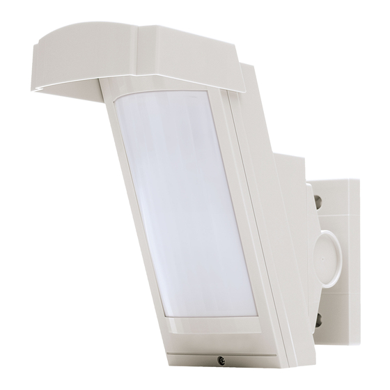
High mount outdoor detector
Hide thumbs
Also See for HX-40:
- Installation instructions manual (72 pages) ,
- Installation instructions manual (13 pages) ,
- Installation instructions manual (20 pages)
Table of Contents
Advertisement
High Mount
High Mount
Outdoor Detector
Outdoor Detector
HX-40/40AM/
HX-40/40AM/
40DAM
40DAM
HX-40
2 PIRs standard model
HX-40AM
HX-40 with anti-masking
HX-40DAM HX-40AM with micro-wave
•
3.0 m high mount detection area (12.0 m)
•
Unique pyro element
•
Intelligent AND logic
•
Dual signal processing logic
•
Vegetation sway analysis logic
•
Ideal detection area setting
•
Digital anti-masking (AM/DAM model only)
•
Microwave range selector (DAM model only)
INSTALLATION INSTRUCTIONS
CONTENTS
1 INSTALLATION PRECAUTIONS ............2
1-1 BEFORE INSTALLATION ................2
1-2 PARTS IDENTIFICATION ................3
1-3 KNOCKOUTS ..................................4
1-4 DETECTION AREA..........................5
DETECTION LENGTH ....................5
2 INSTALLATION .......................................6
2-1 MOUNTING WITH BRACKET .........6
ANGLE.............................................8
BRACKET ........................................9
2-4 WIRING .........................................10
2-5 WALL TAMPER (OPTION) ............ 11
3 WALK TEST ..........................................12
4 SETTING ..............................................13
5 AREA ADJUSTMENT ...........................16
6 LED INDICATION .................................17
7 SPECIFICATIONS ................................18
7-1 SPECIFICATIONS .........................18
7-2 DIMENSIONS ................................19
- 1 -
NO.59-1501-3
N219
Advertisement
Table of Contents

Related Manuals for Optex HX-40


Summary of Contents for Optex HX-40
-
Page 1: Table Of Contents
CONTENTS 1 INSTALLATION PRECAUTIONS ....2 HX-40 2 PIRs standard model 1-1 BEFORE INSTALLATION ....2 HX-40AM HX-40 with anti-masking 1-2 PARTS IDENTIFICATION ....3 HX-40DAM HX-40AM with micro-wave 1-3 KNOCKOUTS ........4 1-4 DETECTION AREA......5 • 3.0 m high mount detection area (12.0 m) 1-5 DETERMINATION OF PIR •... -
Page 2: Installation Precautions
INSTALLATION PRECAUTIONS BEFORE INSTALLATION Failure to follow the instructions provided with this indication and improper Warning handling may cause death or serious injury. Failure to follow the instructions provided with this indication and improper Caution handling may cause injury and/or property damage. The check mark indicates recommendation. -
Page 3: Parts Identification
HX-40 HX-40AM -Precautions for installing two or more sensors HX-40DAM Do not install two or more HX-40DAM’s units side-by-side or face-to-face. Instead, install them back-to-back. If mounting on the same wall, be sure they are at least 1.0 m (3'3") apart from each other. -
Page 4: Knockouts
KNOCKOUTS Bracket Main unit Wiring Hole Wiring (Off-the-shelf) magnet switch knockout installation position Wiring Hole Wiring sponge pad Do not touch Up-Down For wall For switch lock screw fastening box fastening For bracket For wall fastening/bracket fastening For main unit fastening Adjustment screw Up-Down lock screw (installation pitch 83.5 mm (3.29")) -
Page 5: Detection Area
DETECTION AREA Side view Top view (Mounting height: 3.0 m (9'10")) (ft.) (ft.) (ft.) 12.0 m (ft.) (Mounting height: 2.5 m (8'2")) (ft.) 12.0 m (ft.) • Vertical angle: 1 click (2.5°) upward (Refer to “caution” in 2-2). (ft.) DETERMINATION OF PIR DETECTION LENGTH To adjust the detection length, apply the masking seals to the back of the lens according to the required detection length. -
Page 6: Installation
INSTALLATION Use the bracket for normal installation. The unit may be mounted directly on the wall, without the bracket, only if the following three conditions are not; • The mounting height 3.0 m (9'10"). • Horizontal direction adjustment is unnecessary. •... - Page 7 Determine the horizontal direction (left or Open the wiring knockout. right) of the detector before installing the bracket on the wall. To the right To the left Wiring knockout Tighten screws 1 and 2, adjust the bracket Open the Up-Down lock screw knockout angle (refer to 2-2), then tighten screw 3.
-
Page 8: Adjusting The Vertical Angle
ADJUSTING THE VERTICAL ANGLE For best performance, install detector parallel to the ground. Decide the detection length. If you choose 9.0 m/5.5 m/4.0 m, mask the unnecessary lens with masking seals. Refer to the 1-5 for the details. 12.0 m (40') Perform the walk test to check if detector is parallel to the ground. -
Page 9: Mounting Without Bracket
MOUNTING WITHOUT BRACKET Open the wiring knockout with suitable Pull the wire through the base knockout. tool e.g. screwdriver. Wiring sponge pad Install main unit after wiring to the Fasten the base to the wall. terminal. - 9 -... -
Page 10: Wiring
WIRING Power wires should not exceed the following lengths. HX-40 HX-40AM HX-40DAM WIRE GAUGE 12 V 14 V 12 V 14 V 12 V 14 V 160 m 360 m 140 m 310 m 120 m 250 m AWG22 (0.33 mm... -
Page 11: Wall Tamper (Option)
WALL TAMPER (OPTION) Universal magnet switch may be mounted as a wall tamper. Installation space for universal magnet switch is provided on the back of the main unit and the bracket. Maximum size of an applicable universal magnet switch: D 9 mm (0.35'') × W 40 mm (1.57'') × H 9 mm (0.35''). -
Page 12: Walk Test
When using the bracket Tilt the bracket about 45° and pass through the wire. Wiring sponge pad Magnet switch Install the bracket and the main unit to Connect the universal magnet switch wiring the wall surface. to the tamper terminal of the main unit. WALK TEST Set the DIP switch 1 (LED ON/OFF) to Check that the detector detects an... -
Page 13: Setting
3. AUX INPUT MW sensitivity 4. TROUBLE OUTPUT adjustment 5. MICROWAVE IMMUNITY 6. (Reserved) Anti masking sensitibity selector Do not touch PIR sensitivity selector HX-40 HX-40AM -LED ON/OFF DIP switch HX-40DAM POSITION FUNCTION The LED lights when someone is (Factory detected. default) The LED does not light even if someone is detected. - Page 14 HX-40 HX-40AM -AUX INPUT DIP switch HX-40DAM By connecting a satellite unit (another warning sensor), you can extend the detection area and correct false alarms. As a satellite unit, you can use any general no-voltage contact output (NC) warning sensor, including the following.
- Page 15 HX-40 RANGE SELECTOR/ HX-40AM SENSITIVITY -MW RANGE SELECTOR/MW SENSITIVITY ADJUSTMENT ADJUSTMENT HX-40DAM DETECTION AREA MW RANGE MW SENSITIVITY PIR AREA SETTING (SIDE VIEW) SELECTOR ADJUSTMENT LONG 12.0 m (40') SHORT LONG Factory default SHORT HIGH 9.0 m SHORT (29'6'') LONG SHORT 5.5 m...
-
Page 16: Area Adjustment
HX-40 HX-40AM -PIR SENSITIVITY SENSITIVITY SELECTOR HX-40DAM POSITION FUNCTION HIGH HIGH High sensitivity MIDDLE Middle sensitivity MIDDLE (Factory default) Low sensitivity HX-40 ANTI-MASKING HX-40AM -ANTI-MASKING SENSITIVITY SENSITIVITY SELECTOR HX-40DAM POSITION FUNCTION HIGH High sensitivity HIGH Standard sensitivity (Factory default) Disabled Caution>>... -
Page 17: Led Indication
LED INDICATION Yellow Blink Light (HX-40DAM only) Green (HX-40DAM only) -HX-40/40AM DETECTOR CONDITION LED INDICATOR (RED ONLY) Warm-up Blinks for approx. 60 sec. Alarm Lights for 2 sec. Anti-Masking booting (Anti-Masking Blinks 2 times and goes off for 5 sec. and then repeats for 180 sec. -
Page 18: Specifications
SPECIFICATIONS SPECIFICATIONS Model HX-40 HX-40AM HX-40DAM Detection method Passive infrared Passive infrared & Microwave PIR Coverage 12.0 m (40') 85° wide / 94 zones PIR distance limit 4.0 m, 5.5 m, 9.0 m (13'1", 18'1", 29'6") Detectable speed 0.3 m/s – 1.5 m/s (1'/s – 4'11"/s) Sensitivity 2.0°C (3.6°F) at 0.6 m/s... -
Page 19: Dimensions
DIMENSIONS Using bracket and hood Without bracket and hood 266 (10.47) 99 (3.90) 148 (5.83) 92 (3.62) Unit: mm (inch) Unit: mm (inch) - 19 -... - Page 20 (1) This device may not cause harmful interference, and (2) this device must accept any interference received, including interference that may cause undesired operation. The HX-40 series is only a part of a complete system, therefore we cannot accept complete responsibility for any damages or other consequences resulting from an intrusion.
Need help?
Do you have a question about the HX-40 and is the answer not in the manual?
Questions and answers