Table of Contents
Advertisement
Quick Links
Advertisement
Table of Contents

Related Manuals for ATEN CL1000N-FR


Summary of Contents for ATEN CL1000N-FR
- Page 1 LCD Console CL1000M / CL1000N User Manual www.aten.com...
-
Page 2: Emc Information
CL1000M / CL1000N User Manual EMC Information FEDERAL COMMUNICATIONS COMMISSION INTERFERENCE STATEMENT: This equipment has been tested and found to comply with the limits for a Class A digital device, pursuant to Part 15 of the FCC Rules. These limits are designed to provide reasonable protection against harmful interference when the equipment is operated in a commercial environment. -
Page 3: Sj/T 11364-2006
CL1000M / CL1000N User Manual SJ/T 11364-2006 The following contains information that relates to China. -
Page 4: User Information
User Information Online Registration Be sure to register your product at our online support center: International http://eservice.aten.com Telephone Support For telephone support, call this number: International 886-2-8692-6959 China 86-400-810-0-810 Japan 81-3-5615-5811 Korea 82-2-467-6789 North America 1-888-999-ATEN ext 4988 United Kingdom 44-8-4481-58923... -
Page 5: User Notice
CL1000M / CL1000N User Manual User Notice All information, documentation, and specifications contained in this manual are subject to change without prior notification by the manufacturer. The manufacturer makes no representations or warranties, either expressed or implied, with respect to the contents hereof and specifically disclaims any warranties as to merchantability or fitness for any particular purpose. -
Page 6: Package Contents
© Copyright 2017 ATEN® International Co., Ltd. Manual Date: 2017-10-05 ATEN and the ATEN logo are registered trademarks of ATEN International Co., Ltd. All rights reserved. All other brand names and trademarks are the registered property of their respective owners. -
Page 7: Table Of Contents
CL1000M / CL1000N User Manual Contents EMC Information ..........ii RoHS. - Page 8 CL1000M / CL1000N User Manual Adjustment Settings ........20 Manufacturing Number .
-
Page 9: About This Manual
CL1000M / CL1000N User Manual About this Manual This User Manual is provided to help you get the most from your CL1000M / CL1000N system. It covers all aspects of installation, configuration and operation. An overview of the information found in the manual is provided below. -
Page 10: Conventions
For information about all ATEN products and how they can help you connect without limits, visit ATEN on the Web or contact an ATEN Authorized Reseller. Visit ATEN on the Web for a list of locations and telephone numbers: International http://www.aten.com... -
Page 11: Chapter 1 Introduction
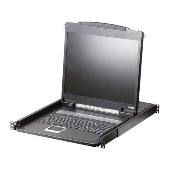
Chapter 1 Introduction Overview The CL1000M / CL1000N is a LCD KVM console that features an integrated 17” (CL1000M) or 19” (CL1000N) LED-backlit LCD panel, full keyboard, and touchpad in a 1U rack-mountable sliding housing. These models provide convenient ‘at the rack’ console access to KVM switches already installed at your site. -
Page 12: Features
CL1000M / CL1000N User Manual Features Exclusive LED illumination light - designed by ATEN to illuminate the keyboard and touchpad to allow visibility in low-light conditions Integrated KVM console with a 17”(CL1000M) or 19" (CL1000N) LED- backlit LCD monitor in a sliding housing with top and bottom clearance... -
Page 13: Requirements
Chapter 1. Introduction Requirements Switches and Computers The CL1000M / CL1000N supports most KVM switches that have PS/2 console port connectors. If you are unsure whether your switch is supported or not, check with your dealer. The integrated LCD monitor's maximum resolution is 1280 x 1024 @ 75 Hz. -
Page 14: Components
CL1000M / CL1000N User Manual Components CL1000M Front View No. Component Description Handle Pull to slide the KVM module out; push to slide the module in. Slide Release In order to slide the console out, you must first release it by moving this tab sideways. -
Page 15: Cl1000M Rear View
Chapter 1. Introduction Rack Mounting The rack mounting brackets located at each corner of the unit Brackets secure the chassis to a system rack. Lock LEDs The Num Lock, Caps Lock, Scroll Lock LEDs are located here. Reset Switch Located to the right of the Lock LEDs. Press this recessed switch in with a thin object to perform a system reset. -
Page 16: Cl1000N Front View
CL1000M / CL1000N User Manual CL1000N Front View No. Component Description Handle Pull to slide the KVM module out; push to slide the module in. Slide Release In order to slide the console out, you must first release it by moving this tab sideways. -
Page 17: Cl1000N Rear View
Chapter 1. Introduction Rack Mounting The rack mounting brackets located at each corner of the unit Brackets secure the chassis to a system rack. Lock LEDs The Num Lock, Caps Lock, Scroll Lock LEDs are located here. LCD On / Off Push this button to turn the LCD monitor on and off. - Page 18 CL1000M / CL1000N User Manual This Page Intentionally Left Blank...
-
Page 19: Chapter 2. Hardware Setup
Chapter 2 Hardware Setup Before you Begin 1. Important safety information regardin g the placement of this device is provided on page 23. Please review it before proceeding. 2. Make sure that power to all the devices you will be connecting up have been turned off. - Page 20 CL1000M / CL1000N User Manual To rack mount the CL1000M, do the following: 1. While one person positions the CL1000M in the rack and holds it in place, the second person loosely screws the front brackets to the rack. 2. While the first person still holds the CL1000M in place, the second person slides the L brackets into the CL1000M's side mounting brackets from the rear until the bracket flanges contact the rack, then screws the L brackets to the rack.
-
Page 21: Cl1000N Standard Rack Mounting
Chapter 2. Hardware Setup CL1000N Standard Rack Mounting A standard rack mount kit is provided with your CL1000N. The kit enables the console to be mounted in rack with a depth of 52–85 cm. L Brackets Note: 1. It takes two people to mount the console: one to hold it in place, the other to screw it in. - Page 22 CL1000M / CL1000N User Manual To rack mount the CL1000N, do the following: 1. While one person positions the CL1000N in the rack and holds it in place, the second person loosely screws the front brackets to the rack. 2. While the first person still holds the CL1000N in place, the second person slides the L brackets into the LCD itself from the rear until the bracket flanges contact the rack, then screws the L brackets to the rack.
-
Page 23: Cl1000M / Cl1000N Installation
Chapter 2. Hardware Setup CL1000M / CL1000N Installation Refer to the installation diagram as you perform the installation steps. The numbers in the diagrams correspond to the numbers of the steps. 1. Plug the SPHD connector end of the KVM cable provided with this unit into the CL1000M / CL1000N's KVM port. - Page 24 CL1000M / CL1000N User Manual This Page Intentionally Left Blank...
-
Page 25: Chapter 3 Operation
Chapter 3 Operation CL1000M Opening the Console The CL1000M's console is located under the top cover. To access the console, slide the console module out and raise the cover. Note: As a safety precaution, to keep the console from accidentally sliding out, the console is locked into the In position. -
Page 26: Closing The Console
CL1000M / CL1000N User Manual Closing the Console To slide the CL1000M module back in, close the cover and do the following: 1. Pull the safety catches on the unit's side rails toward you and push the module in until it stops. 2. -
Page 27: Cl1000N Opening The Console
Chapter 3. Operation CL1000N Opening the Console The CL1000N's console is located under the top cover. To access the console, slide the console module out and raise the cover. Note: As a safety precaution, to keep the console from accidentally sliding out, the console is locked into the In position. -
Page 28: Closing The Console
CL1000M / CL1000N User Manual Closing the Console To slide the CL1000N module back in, do the following: 1. Close the cover. 2. Push the module all the way in. -
Page 29: Operating Precautions
Chapter 3. Operation Operating Precautions The maximum load bearing capacity of the keyboard module is 30 kg. Failure to heed the information below can result in damage to the keyboard module. Right! Rest your hands and arms lightly on the keyboard module as you work. -
Page 30: Lcd Osd Configuration
CL1000M / CL1000N User Manual LCD OSD Configuration LCD Buttons The LCD OSD allows you to set up and configure the LCD display. Four buttons are used to perform the configuration, as described in the table, below: Button Function MENU When you have not entered the LCD OSD Menu function, pressing this button invokes the Menu function, and brings up the Main Menu. -
Page 31: Manufacturing Number
Manufacturing Number The “MFG Number” (Manufacturing Number) is an internal serial number used by ATEN’s factory and technical support staff to identify products. This number does not affect products’ warranty. If your product requires after-sales services, you may provide the MFG Number to ATEN’s sales or technical... -
Page 32: Port Id Numbering & Port Selection
CL1000M / CL1000N User Manual Port ID Numbering & Port Selection Port ID numbering and Port Selection follow the method used by the KVM switch connected to the CL1000M / CL1000N. Consult your KVM switch's User Manual for details. -
Page 33: Appendix
Appendix Safety Instructions General This product is for indoor use only. Read all of these instructions. Save them for future reference. Follow all warnings and instructions marked on the device. To prevent damage to your installation it is important that all devices are properly grounded. - Page 34 CL1000M / CL1000N User Manual If an extension cord is used with this device make sure that the total of the ampere ratings of all products used on this cord does not exceed the extension cord ampere rating. Make sure that the total of all products plugged into the wall outlet does not exceed 15 amperes.
-
Page 35: Rack Mounting
Appendix Rack Mounting Before working on the rack, make sure that the stabilizers are secured to the rack, extended to the floor, and that the full weight of the rack rests on the floor. Install front and side stabilizers on a single rack or front stabilizers for joined multiple racks before working on the rack. -
Page 36: Consignes De Sécurité
CL1000M / CL1000N User Manual Consignes de sécurité Général Ce produit est destiné exclusivement à une utilisation à l’intérieur. Veuillez lire la totalité de ces instructions. Conservez-les afin de pouvoir vous y référer ultérieurement. Respectez l’ensemble des avertissements et instructions inscrits sur l’appareil. - Page 37 Appendix L’équipement doit être installé à proximité de la prise murale et le dispositif de déconnexion (prise de courant femelle) doit être facile d’accès. La prise murale doit être installée à proximité de l’équipement et doit être facile d’accès. Veillez à ce que rien ne repose sur le cordon d’alimentation ou les câbles. Acheminez le cordon d’alimentation et les câbles de sorte que personne ne puisse marcher ou trébucher dessus.
- Page 38 CL1000M / CL1000N User Manual L’unité a été exposée à la pluie ou à l’eau. L’unité est tombée ou le boîtier a été endommagé. Les performances de l’unité sont visiblement altérées, ce qui indique la nécessité d’une réparation. L’unité ne fonctionne pas normalement bien que les instructions d’utilisation soient respectées.
-
Page 39: Montage Sur Bâti
Appendix Montage sur bâti Avant de travailler sur le bâti, assurez-vous que les stabilisateurs sont bien fixées sur le bâti, qu’ils sont étendus au sol et que tout le poids du bâti repose sur le sol. Installez les stabilisateurs avant et latéraux sur un même bâti ou bien les stabilisateurs avant si plusieurs bâtis sont réunis, avant de travailler sur le bâti. -
Page 40: Technical Support
CL1000M / CL1000N User Manual Technical Support International For online technical support – including troubleshooting, documentation, and software updates: http://eservice.aten.com For telephone support, see page iv. North America Email Support support@aten-usa.com Online Troubleshooting http://www.aten-usa.com/support Technical Documentation Support Software Updates Telephone Support... -
Page 41: Specifications
Appendix Specifications Function CL1000M CL1000N Connector KVM Ports 1 x SPHD-15 Female 1 x SPHD-15 Female (Yellow) (Yellow) Power 1 x 3-prong AC Socket 1 x 3-prong AC Socket Switches Power 1 x Rocker LCD Adjust 4 x Pushbutton 4 x Pushbutton Reset 1 x Semi-recessed 1 x Semi-recessed... - Page 42 CL1000M / CL1000N User Manual Function CL1000M CL1000N Physical Housing Metal + Plastic Metal + Plastic Properties Weight 12.02 kg 11.06 kg Dimensions (L x W 48.00 x 53.83 x 4.40 cm 48.30 x 58.52 x 4.40 cm x H)
-
Page 43: Cl1000M Optional Rack Mounting
Appendix CL1000M Optional Rack Mounting For convenience and flexibility, three optional rack mounting kits are available for the CL1000M, as shown in the following table: Bracket Type Size (cm) Standard Installation – Long 68.0–100.0 Easy Installation – Short 42.0–70.0 Easy Installation – Long 68.0–105.0 To install the long bracket standard rack mount kit, simply replace the short L brackets on the standard rack mount kit with the long ones, and mount the... - Page 44 CL1000M / CL1000N User Manual 2. Attach the left and right easy-installation mounting rails to the inside of the rack. The flange that supports the console will be to the inside. Rear Flange Slide Bar Sliding Attachment Bracket LEFT Support Rear Flange RAIL Flange...
- Page 45 Appendix 3. Slide the console onto the support flanges. Use the screws supplied with this package to loosely attach the front of the console to the front of the rack (only tighten the screws part way). Phillips I head M4 x 6 4.
- Page 46 CL1000M / CL1000N User Manual 5. Slide the console open and closed a couple of times to be sure that it is properly aligned and operating smoothly. (See page 15 for opening and closing procedures.) 6. After determining that the console is properly lined up and operating correctly, finish up by fully tightening down the partially tightened front attachment screws inserted in step 3.
-
Page 47: Cl1000N Optional Rack Mounting
Appendix CL1000N Optional Rack Mounting For convenience and flexibility, three optional rack mounting kits are available for the CL1000N, as shown in the following table: Bracket Type Size (cm) Standard Installation – Long 70.0–105.0 Easy Installation – Short 57.0–70.0 Easy Installation – Long 68.0–105.0 To install the long bracket standard rack mount kit, simply replace the short L brackets on the standard rack mount kit with the long ones, and mount the... - Page 48 CL1000M / CL1000N User Manual 2. Attach the left and right easy-installation mounting rails to the inside of the rack. The flange that supports the console will be to the inside. Rear Flang Rear Flang Slide bar Slide bar Rear Attachment Rear Attachment Sliding Bracket Sliding Bracket...
- Page 49 Appendix 3. Slide the console onto the support flanges. Use the screws supplied with this package to loosely attach the front of the console to the front of the rack (only tighten the screws part way). Phillips I Head M4L6 4.
-
Page 50: About Sphd Connectors
CL1000M / CL1000N User Manual 5. Slide the console open and closed a couple of times to be sure that it is properly aligned and operating smoothly. (See page 17 for opening and closing procedures.) 6. After determining that the console is properly lined up and operating correctly, finish up by fully tightening down the partially tightened front attachment screws inserted in step 3. -
Page 51: Limited Hardware Warranty
ATEN will provide a repair service, without charge, during the Warranty Period. If a product is defective, ATEN will, at its discretion, have the option to (1) repair said product with new or repaired components, or (2) replace the entire product with an identical product or with a similar product which fulfills the same function as the defective product. - Page 52 CL1000M / CL1000N User Manual This Page Intentionally Left Blank...
Need help?
Do you have a question about the CL1000N-FR and is the answer not in the manual?
Questions and answers