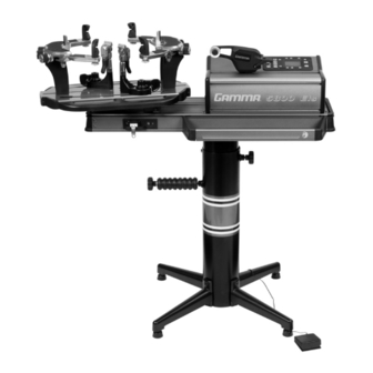
Gamma 5800 Els Owner's Manual
6 point mounting
Hide thumbs
Also See for 5800 Els:
- Owner's manual (24 pages) ,
- Owner's manual (25 pages) ,
- Owner's manual (32 pages)
Table of Contents
Advertisement
Advertisement
Table of Contents

Related Manuals for Gamma 5800 Els


Summary of Contents for Gamma 5800 Els
- Page 1 5800 Els STRINGING MACHINE 6 POINT MOUNTING OWNER’S MANUAL Issue 7 - June 2014...
-
Page 2: Table Of Contents
Should any defects develop under normal use within the specif ed time periods, GAMMA will at its option, repair or replace the defective EQUIPMENT provided it is returned to GAMMA prepaid at the purchaser’s expense. -
Page 3: Features
FEATURES MACHINE FEATURES Electric Constant Pull Tensioner with 11.0 to 90.0 lbs Tension Range Digital Tension Setting with LCD Display Parallel Jaw Linear Gripper Professional Six Point “Quick Mount” Racquet Mounting System- Accommodates All Racquets Professional “Quick Action” Dual Action, Rotating, Metal Fixed String Clamps with Diamond Dust Coating ... -
Page 4: Unpacking & Assembly Instructions
Please save the cartons and packing materials for possible shipments in the future. Gamma Sports cannot be responsible for machines that are not returned, shipped in their original, undamaged packaging. - Page 5 ASSEMBLY INSTRUCTIONS Floor Stand Leg Assembly The stringing machine uses a four leg f oor stand design. The legs must be assembled to the Lower Column before use. Remove all parts from the shipping carton to con f rm that contents match the list of parts on Page 4.
- Page 6 ASSEMBLY INSTRUCTIONS Floor Stand Height Adjustment The height of the machine is adjustable from 39” to 46” in approximate 1” increments. To change the height, remove the socket head cap screw from its current position and place it in the appropriate hole to set the desired height of the machine.
-
Page 7: String Reel Holder Installation
STRING REEL HOLDER INSTALLATION The String Reel Holder pin is an 8 mm rod with threads on both ends and f at surfaces machined on one end. Thread the end of the pin without the f at surfaces into the threaded boss on the right side of the Lower Column. - Page 8 ASSEMBLY INSTRUCTIONS Turntable and Mounting System Installation To install the Turntable position the Turntable over the turntable pin and align the bolts, located in the poly bag, with the holes in the f ange. Secure them with the included hex wrench. String Clamp Installation The post of the String Clamp and tube of the String Clamp Base are treated with grease to...
-
Page 9: Power Connection & Controls
POWER CONNECTION & CONTROLS Front Panel Features A - String Gripper B - Tension Lever Switch C - LCD Display and Control Panel Back Panel Features Lighted Power Switch A/C Power Cord Socket Foot Pedal Switch Receptacle String Length Meter Receptacle Instructions for Power Connection and Controls CAUTION ! Before connecting to the power supply, check the voltage source that the machine is being connected to. -
Page 10: Control Panel Functions And Features
CONTROL PANEL FEATURES ESC Button - Press to return to the ENTER Button - Press to conf rm and Stringing Screen from the Settings save changes to any machine settings Screen, String Length Meter Screen or and to zero the String Length Meter. to cancel a change being made to one of the functional settings. -
Page 11: Display Screen
DISPLAY SCREENS Language Selection Screen At start-up, if a language other than English is desired, press any one of the F6-F8 but- tons when the Start-up Screen appears to change to the Language Selection Screen. Pressing any one of the F2-F8 buttons will scroll through the available languages. -
Page 12: Machine Functions
MACHINE FUNCTIONS Setting Tension To change the Tension Setting press F2 to increase the Tension Setting in the tens place, F3 to increase the Tension Setting in the units place and F4 to increase the Tension Setting in the tenths place. decrease the Tension Setting press F6 to decrease the Tension Setting in the tens place, F7 to decrease the Tension Setting... - Page 13 MACHINE FUNCTIONS Permanent Memory Settings There are 9 permanent Memory Settings that can be used to store 9 combinations of machine settings. Pressing the MEMOR Y button will scroll through the 9 Memory Settings in increasing order. To reverse the scrolling order, press the F5 button.
- Page 14 MACHINE FUNCTIONS Setting the Pulling Speed from the Stringing Screen To change the Pulling Speed Setting while in the Stringing Screen, f rst press the PULLING SPEED button to display the Pull- ing Speed Icon and Pulling Speed Setting on the display . Then press and hold the PULLING SPEED button again until the Pulling Speed Setting is highlighted above the Pulling Speed Icon.
- Page 15 MACHINE FUNCTIONS Pre-stretch Function The Pre-stretch function is used to pre- stretch strings by increasing the applied tension by a set percentage over the tension setting before releasing the string and re- pulling to the desired tension. This function helps to reduce the amount of tension loss in the strings over time.
- Page 16 MACHINE FUNCTIONS Knot String Function The Knot String function is used to increase the applied tension by a set percentage over the tension setting on the last main string or cross string pulled before tying of f. This function helps to compensate for tension loss caused by the slack portion of the string from the string clamp to the tie-off knot.
-
Page 17: Mounting The Frame
MOUNTING THE FRAME Adjusting the Frame Mounting Stands Loosen the lock bolts of the frame Mounting Stands and space them apart with the Frame Support Slides separated by the approximate length of the racquet head. Although it is not required, it is good practice to center the Mounting Stands on the Turntable. -
Page 18: Stringing The Frame
MOUNTING THE FRAME Securing the Frame Shoulder Clamps Lock the Shoulder Supports in position by turning the knob at the base clockwise. Repeat the adjustment procedure for the remaining support post. Re-tighten all of the Frame Supports in the same order as before. Do not overtighten any of the supports as racquet damage may occur. - Page 19 STRINGING THE FRAME Stringing the Mains Follow the manufacturer ’s recommended stringing pattern for one or two piece stringing. To determine which end of the racquet to start installing the string count the number of grommet holes located in the throat bridge. If there are 2 or 6 holes start main strings at the center 2 holes of the throat bridge.
- Page 20 STRINGING THE FRAME Apply tension to the string by pressing the Ten- sion Lever Switch or the Foot Pedal Switch. The String Gripper will move to the right, away from the racquet, and gradually apply tension to the string. Tension Lever Switch As tension is applied to the string, the 4 Tension Indicator LEDs on the Control Panel will progres- sively f ash until all 4 are lit indicating that the...
- Page 21 STRINGING THE FRAME Clamping the First Main String Secure the tensioned main string using the remaining f xed clamp. Repeat the proce- dure for all of the remaining main strings and tie off at the appropriate holes following the racquet manufacturers specif cations. This will determine the starting point for the cross strings.
-
Page 22: String Length Meter
STRING LENGTH METER OPERATION String Length Meter Press the String Length Meter (SLM) button to enable the SLM function and display the SLM screen. To change the measurement units from Feet (FT) and Meters (M) press the SLM button to toggle between FT and M. To measure a length of string from a reel or set of string, insert the end of the string through the loop from the backside of the... -
Page 23: Additional Features
ADDITIONAL FEATURES Turntable Brake The Turntable may be locked in any position. Flip the lever to the right to lock the Turntable Brake and f ip the lever to the left to release the Turntable Brake. Storage Drawers There are two Storage Drawers located in the Base of the machine. -
Page 24: Pathfinder Awl
PATHFINDER AWL The machine includes the Pathf nder String- ing Awl which creates a pathway between or around strings to make inserting a string through blocked grommets easier and quicker . Insert the awl through the grommet hole in the same manner as for traditional awls. The Pathf nder Awl must be in the closed position before insertion. -
Page 25: Maintenance & Adjustments
MAINTENANCE & ADJUSTMENTS Tension Calibration Procedure During power up press both ESC and EN- TER buttons to enable the calibration mode. The display will show 22 lbs or 10 kgs. KG/ LBS can be changed at any time by pressing the LB/KG Button. - Page 26 MAINTENANCE & ADJUSTMENTS Adjusting the Clamp Base In the event the Locking Lever rotation is insuff cient to ensure smooth operation of the Clamp Base, very minor adjustments to the Clamp Base Locking Nut can be made with a 17mm socket. Tighten or loosen the locking nut in very small increments to provide more clamping pressure or running...
-
Page 27: Troubleshooting Tips
TROUBLESHOOTING TIPS PROBLEM SOLUTION String slips in clamps - Adjust gap between clamp jaws - Clean clamp jaws String slips in gripper - Adjust gripper jaw stop screw - Clean gripper jaws String clamp base slips on turntable - Clean bottom of clamp & top of turntable with alcohol - Adjust clamp base locking nut String tension too tight or too loose... -
Page 28: Parts List
PARTS LIST PART # DESCRIPTION PART # DESCRIPTION CAP SCREW - M8x30 A220 SUPP ARM KNOB & SCREW WASHER- M10 A220 FRAME KNOB & SCREW STAND BRAKE KNOB ADJ KNOB RUBBER GRIP SHORT LEG A220 SHOULDER V-MNT (BLK) FLAT HEAD SCREW- M8x25 A220 FRAME SUPPORT LEVELING FOOT A220 SC MNTING STAND... -
Page 29: Parts Drawing
PARTS SUMMARY MDCSC 13 MQAC12 MMSPP 13 MBMSP 11 MFSPP 13... - Page 30 NOTES...
- Page 31 NOTES...
- Page 32 MMAN-48 (MG58E-17) GAMMA SPORTS 200 Waterfront Drive Pittsburgh, Pennsylvania 15222 Phone: 800.333.0337 Fax: 412.323.0317 Visit our website at www.gammasports.com Copyright 2014 GAMMA Sports - All Rights Reserved...
Need help?
Do you have a question about the 5800 Els and is the answer not in the manual?
Questions and answers