Table of Contents
Advertisement
Quick Links
Advertisement
Table of Contents

Related Manuals for Analog way ops300

Summary of Contents for Analog way ops300
- Page 1 USER MANUAL version 4.00 Ops300...
-
Page 3: Table Of Contents
Output specifications Communication specifications Environmental specifications Pin outs HDCP compliance CONNECTING THE OPS300 3-1. CONNECTING THE OPS300 3-2. THE OPS300 REAR PANEL Overview Inputs #1 to #8 DVI Inputs #1 - #2 SD/HD-SDI Inputs #1 - #2 Preview Outputs Main Outputs... - Page 4 OPERATING THE OPS300 4-1. THE OPS300 FRONT PANEL Overview On/Off button Menu screen Menu scroll knob Control section Layer selection section Take button Input selection section Freeze button Audio-Video input 8 T-Bar Effect selection button Preset selection button 4-2. THE OPS300 MENU...
- Page 5 6-3. TRK-800 - Ref. TRK-800 6-4. RK-300 - Ref. RK-300 EXAMPLES AND TIPS 7-1. ABOUT EXAMPLES 7-2. EXAMPLES 7-3. EXTERNAL PROGRAMMING WARRANTY AND SERVICES INFORMATION 8-1. ANALOG WAY LIMITED WARRANTY 8-2. SERVICES AND RMA CONTACT INFORMATION HOW TO CONTACT US INFORMATION ON DISPOSAL...
-
Page 6: Introduction
* NOTE * : We recommend resetting the device to its default values every time you set up your shows or events (see the “Operating The OPS300” chapter, p25). MIXER MODE This mode allows for a single... -
Page 7: Useful Terms And Definitions
Frame is a full screen image which is selected from one of the eight still frames which you can capture with the OPS300. A Frame can be flash captured from any video or computer source plugged into the machine (8 max). -
Page 8: Hardware Installation
HARDWARE INSTALLATION 2-1. SAFETY INSTRUCTION CAUTION: All of the safety and operating instructions should be read before the product is operated and should be maintained for further reference. Please follow all the warnings regarding this product and its operating instructions. •... - Page 9 INSTRUCTIONS DE SECURITE Afin de mieux comprendre le fonctionnement de cet appareil nous vous conseillons de bien lire toutes les consignes de sécurité et de fonctionnement de l’appareil avant utilisation. Conservez les instructions de sécurité et de fonctionnement afin de pouvoir les consulter ultérieurement. Respectez toutes les consignes marquées dans la documentation, sur le produit et sur ce document.
- Page 10 INSTRUZIONI DI SECUREZZA Allo scopo di capire meglio il funzionamento di questa apparecchiatura vi consigliamo di leggere bene tutti i consigli di sicurezza e di funzionamento prima dell’utilizzo. Conservare le istruzioni di sicurezza e di funzionamento al fine di poterle consultare ulteriormente. Seguire tutti i consigli indicati su questo manuale e sull’apparecchiatura.
- Page 11 SICHERHEITSHINWEISE Um den Betrieb dieses Geräts zu verstehen, raten wir Ihnen vor der Inbetriebnahme alle Sicherheits und Betriebsanweisungen genau zu lesen. Diese Sicherheits- und Betriebsanweisungen für einen späteren Gebrauch sicher aufbewahren. Alle in den Unterlagen, an dem Gerät und hier angegebenen Sicherheitsanweisungen einhalten.
- Page 12 INSTRUCCIONES DE SEGURIDAD Para comprender mejor el funcionamiento de este aparato, le recomendamos que le acuidadosamente todas las consignas de seguridad y de funcionamiento del aparato antes de usarlo. Conserve las instrucciones de seguridad y de funcionamiento para que pueda consultarlas posteriormente. Respete todas las consignas indicadas en la documentación, relacionadas con el producto y este documento.
-
Page 13: Unpacking And Inspection
2-4. CABLE AND ADAPTOR INFORMATION A large choice of cables and adaptors are compatible with the OPS300. To find which are to be used in your setup, please refer to the Hardware Specifications chapter. Please contact your distributor for a list of... -
Page 14: Hardware Specifications
2-5. HARDWARE SPECIFICATIONS Input specifications • ANALOG COMPUTER: Connectors: Inputs #1 to #5: female HD15. Inputs #6 & #7: female DVI-I (analog pins). Input #8: female HD15. Line frequency: Up to 130 kHz (165 MHz Max pixel rate). Resolution: Up to 1600x1200 @ 165Mhz, 1920x1200px (RB, Max V size: 1200px, Max H size 2048px). - Page 15 • S.VIDEO: Connectors: Inputs #1 to #5: female HD15. Inputs #6 & #7: female DVI-I (analog pins). Input #8: female HD15 + 4-pin MiniDin. Standard: PAL/SECAM: 15.625 kHz - 50Hz - 625 lines. NTSC (3.58 - 4.43 MHz): 15.734 kHz/60Hz/525 lines. Levels: Y = 1 Vp/p (0.7 V Luma + 0.3 V Sync.).
-
Page 16: Output Specifications
Inputs #7 and AUX (or 10-pin MCO male connector) LEFT Input #5 RIGHT (Balanced connection). GROUND(S) LEFT Input #6 RIGHT LEFT DVI 1 RIGHT GROUND(S) LEFT DVI 2 RIGHT Output specifications UNBALANCED • ANALOG OUTPUTS Connector: Outputs #1 (Main) & #2 (Preview): female HD15, DVI-I (analog pins). HDTV Resolutions: Format Ratio... - Page 17 • DVI (Digital Video Interface) OUTPUTS Connector: Outputs #1 (Main) & #2 (Preview): female DVI-I (digital pins). Signal: Digital Visual Interface (DVI)-TMDS single link. HDTV Resolutions: Format Ratio Available Refresh Rates 720p 16 : 9 50Hz 59.94Hz 60Hz 1035i 16 : 10 59.94Hz 60Hz 1080i 16 : 9...
-
Page 18: Communication Specifications
The video output generates a SDI signal in which is embedded only one stereo audio stream. Settings Availability Gain Yes: from - ∞ to +18dB Balanced Audio Left and Right Auxiliary Input Mixing Adjusting Audio Delay Yes: from 0 to 80ms (Automatic or Manual) •... -
Page 19: Environmental Specifications
Environmental specifications Dimensions: W 482 x D 330 x H 88 mm 19”W x 13”D x 3.50”H Weight: 5 kg / 11 lbs (Compatible with a Standard 19” rack, Height = 2 U) Cooling air flow from right side to left side. Max ambient operating temperature: <... -
Page 20: Pinouts
Pinouts • STANDARD VGA 1- Red 6- Red Return 11- ID Bit 0 2- Green 7- Green Return 12- ID Bit 1 3- Blue 8- Blue Return 13- H Sync 4- ID Bit 2 9- No Pin 14- V Sync 5- Test (Gnd) 10- Sync Return 15- ID Bit 3... -
Page 21: Hdcp Compliance
To summarize all HDCP status, please see in the Control Menu -- > HDCP Summary. NOTE: as part of our policy of continuous improvement, Analog Way reserves the right to make design and specification changes for product improvements without prior notice. The performance specification figures indicated are nominal values of production units. -
Page 22: Connecting The Ops300
CONNECTING THE OPS300 3-1. CONNECTING THE OPS300 OPS300 can be set up with up to 12 different sources, and will drive up to 2 digital DVI-D sources, 2 SD- SDI sources and 8 analog computer/video sources simultaneously. The versatility of the... -
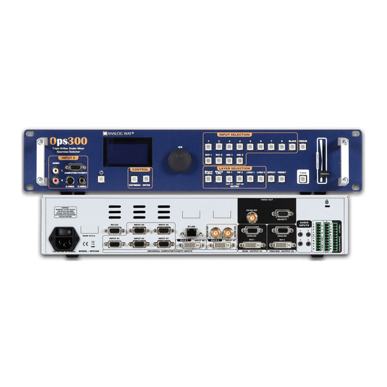
Page 23: The Ops300 Rear Panel
(see also Output Specifications in this chapter). The extra Video Out card installed on the OPS300, can be used for recording, broadcasting or previewing purposes in a wide range of formats for maximum compatibility with industry viewing or recording equipment. -
Page 24: Inputs #1 To #8
Inputs #1 to #8 UNIVERSAL COMPUTER & VIDEO INPUTS Universal Inputs accept computer sources (RGBHV, RGBS, and RGsB (SOG) signals), standard TV/VIDEO sources (Composite video, S.VIDEO), Component video (YUV, RGBS & RGsB (SOG)), and HDTV sources (480p, 720p & 1080i). HD15: 1 x Universal Analog input on female HD15 connector. -
Page 25: Dvi Inputs #1 - #2
RGB/S source. RGBS Source DVI Inputs #1 - #2 DVI AND ANALOG SOURCES: DVI Inputs #1- #2 on the OPS300 accept up to 2 live sources in Digital format. DVI-I: 1 x digital (DVI) and 1 x analog input on female DVI-I universal connector. -
Page 26: Main Outputs
Composite Video to HD SDI. This output can be used to record your show by outputting the same content as the Main output in Mixer Mode, or a choice between output #1 or #2 in Matrix Mode (see also OPS300 Modes, p.4). AUDIO SWITCHER: Audio Stereo Switcher card features 12 inputs and 2 outputs. -
Page 27: Operating The Ops300
OPS300 The highly intuitive front panel of the was designed by Analog Way engineers to simply and quickly meet all of your event needs. Within minutes, you will be able to enjoy its full potential and easily parameter most of its functions, without having to be an expert audio-visual engineer, leaving room for what is most important to our users: concentrating on their event. -
Page 28: Control Section
[EXIT/MENU] and the [ENTER] button in the Control section of the OPS300, allow users to respectively enter and exit the OPS300 menu, and confirm selected menu items. Layer selection section The Layer Selection section allows to select which type of layer to work with: •... -
Page 29: Input Selection Section
The [BLACK] button allows users to remove layer content on screen. Freeze button [FREEZE] button of the OPS300 allows users to freeze the Main output current display or the active input, depending on the freeze mode: FREEZE ALL or freeze the current selected input INPUT FREEZE. -
Page 30: The Ops300 Menu
Home menu Pressing the [MENU] button in the menu section of the OPS300, will display and give you access to the following items on the menu VFD screen: MODE: select to choose which mode the... -
Page 31: Working With The Ops300
Mode, which turns your OPS300 into a true 12 x 2 scaled matrix with numerous effects. * NOTE * : the OPS300 will only let you work on your preview screen (direct access to main screen is locked). In Matrix mode, the OPS300 loses the use of layers, PIPs and logos. -
Page 32: A- Settings In Mixer Mode
A- SETTINGS IN MIXER MODE Source Input selection Plug your sources thanks to the 8 universal inputs, 2 DVI-I Inputs or 2 SDI inputs. Don’t forget that the 2 DVI-I inputs can be used with DVI-D computer sources (DVI#1 & DVI#2) but also with a DVI-I adaptor for analog sources too (source #5 &... -
Page 33: Source Output Selection
Source output selection OPS300 Once your inputs all have been configured, the output settings of the must be set according to the OPS300 machines plugged on your main and preview outputs (video projector, preview monitor...). * NOTE *: if you want to use HDCP content from your sources, be sure to attach HDCP compliant screens or projectors. -
Page 34: Working With Layers
Working with Layers To attach a source to a layer, press the Layer button, press the Source# you want to attach. Ex: [BACKGROUND LIVE ]→ Source #4 The source number 4 will be displayed in the Background live. Press [TAKE] to view the result on the Main screen. - Page 35 One stored Logo selected from 8 available, The Logo#2: One stored Logo selected from 8 available. Opening transitions and closing Live Layers OPS300 When transitioning live layers, depending on how many scalers are in use, the [TAKE] function will act in one of 3 different ways when transitioning the Next Preset (Preview) to the Current Preset (Main): •...
- Page 36 PIP adjustment menu o have access to the PIP adjustment menu, a source has to be affected to your PIP: Press PIP# button → Press source # Once a source is attached to PIP, you can have access to the PIP adjustment Menu: Press PIP # button Press [TAKE]...
- Page 37 Color border Layer transitions & effects OPS300 offers a wide variety of transitions between the scenes you create for your shows and events. It allows for live recall of 4 user presets, each of which you can edit at any given time.
-
Page 38: Capturing Still Frames
Frames are mainly used as backgrounds in a typical show or event setup, and can be recorded from any of the OPS300’ 12 sources and called back at the press of a single button. To use a frame, be sure first that it is well saved, then: Press [BACKGROUND FRAME] button →... - Page 39 Frame setup menu In the frame setup menu, you have the possibility to save a frame, and the possibility to erase a stored frame: Logos/Frames menu → save Frame → Frame # Logos/Frames menu → Erase → Frame # Frames as Layer The background frame is considered as a layer and has some settings available: Transparency, Opening/Closing effect, Smooth move and Status.
-
Page 40: Capturing Logos
Select the logo number you want to save and wait until the unit finish saving. Your logo is now saved and you can use it through the background logo button. You can save up to 8 logos with the OPS300. The capture of logos can be done only with the following conditions:... -
Page 41: Memorizing Logos
Memorizing logos in the OPS300 1. In the Input Selection section, press the source button (#1 to #12) of the source you wish to record as a logo. The source button will start blinking. 2. Select the Logos/Frames menu by scrolling through the menu with the scroll knob, then pressing the [ENTER] button. -
Page 42: Creating Presets
10 stereo inputs, 1 auxiliary input, and 2 stereo embedded SDI audio inputs (via the SDI BNC connectors), all accessible via the Audio menu of the OPS300, and which can be assigned to one or both of the 2 independant symetrical/asymetrical outputs of the device. -
Page 43: Audio Configuration
Audio configuration To configure audio settings of the OPS300, plug all audio inputs into the device, and navigate to the Audio menu. 1. Choose the Audio mode, Break Away or Top Layer Follow, which you wish the audio to work in. - Page 44 Transparent Background - Transparent Background allows you to remove the black band on sources in the background live layer in order to display behind a background frame or background color. Background Frame Image Live Smooth Move effect - Smooth Move PIP control the acceleration of the PIP. The time can be different between the opening and closing PIP.
- Page 45 Working with DSK (Chroma / Luma key) OPS300 allows to use a live source with green or blue (or any color) background and to key it over another live input. - Background is removed and replaced by another source. - Title can be keyed (DSK) on Analog or Digital Sources.
- Page 46 For Chroma Key: Chroma Keying is used to key from a particular color. It produces a soft-edged key which is most suitable for moving images and “weatherman” style applications. Color grabber: Select Chroma Key menu - > Select Color grabber menu Using a crosshair, you can select a particular hue based on what is on screen.
- Page 47 This item gives information about the new “Motion correction” setting added in the OPS300 device. - Aim of the “Motion Correction” setting: The aim of the “motion correction” setting is to correct a “comb effect” sometime visible on OPS300 device. From the front panel, a new setting has been added in the Menu/Image/Advanced section.
- Page 48 OPS300 Aspect Ratio From the Menu select the following Aspect options. Select first the Aspect In then Adjust the Aspect Out. Aspect In Provides aspect ratio adjustments for the content of the image. Affects the raster size of content provided to the signal processing chain.
- Page 49 OPS300 Force to 4/3 From the Image Menu The Force to 4/3 capability allows you to give a 4/3 aspect Ratio to a SDTV Input, this allows you to keep the ratio of a PAL input (ie) shown on a SDTV PAL Output.
- Page 50 In the Control Menu, you will find all setup which cannot be classified in the image, layer, input or output menu. Version: it indicates the actual software version of the OPS300. it can help if you need to contact our technical support team. RS232/LAN: choose your connection type when controling by a R.C.S or an external program.
- Page 51 B- SETTINGS IN NATIVE MATRIX MODE Source Input selection Same as MIXER Mode. Input selection settings Same as MIXER Mode. Source output selection Same as MIXER Mode. * NOTE *: if you want to use HDCP content from your sources, be sure to plug HDCP compliant screens or projectors.
- Page 52 Video Out In Native Matrix mode, the menu “connection mode” allows you to choose recording Output #1 or Output #2. Display Mode Presentation Availability Output #1 OUT #1 Menu→ Video Out → Connection → Output #1 Output #2 Menu→ Video Out → Connection → Output #2 OUT #2 Working with Layers...
- Page 53 Working with Native Matrix Mode To activate the Native Matrix Mode: Mode Menu → Native Matrix mode menu You’ll find all menus from the Mixer Mode in the main menu except some specific matrix function added. To work with Native Matrix Mode, you have to use the Matrix # buttons first. For instance, if you want to put the Frame #1 on the Output #1 and the Live source #3 on the output #2: Press Matrix #1 button →...
- Page 54 Capturing logos Same as Mixer Mode. Memorizing logos Same as Mixer Mode. Working with logos Same as Mixer Mode. Layer transitions & effects Same as Mixer Mode. Creating Presets Same as Mixer Mode. Working with Presets Same as Mixer Mode Working with Audio Same as Mixer Mode Audio configuration...
-
Page 55: Home Menu
HOME MENU MATRIX MODE MIXER MODE [MAIN] [OUT 1] Format : 1920 x 1080 Format : 1920 x 1080 Rate : 50Hz Rate : 50Hz Lock : internal Lock : internal MAIN PREVIEW OUT 1 | OUT 2 ---------+----------------+------------- ---------+--------------+---------- Logo2 | Logo #2 | Logo #8 Live... - Page 56 MODE Mixer Mode Matrix Mode (i1) displayed when plug is not SDI (i10) displayed when plug is not DVI-D Config status INPUT (i2) displayed when type is analog video (i11) displayed when plug is analog Autoset all (i3) displayed when plug is analog (i4) displayed for input ln1, ln2, ln8, DVI1 &...
- Page 57 MAIN OUT (A1) Sync w/OUT 1 (o1) OUTPUT 1 (A2) PREVIEW OUT (A1) Output status OUTPUT 2 (A2) (o1) only for Preview out/Output2 (o2) depending on output format (A1) displayed in Mixer & Quadravision Mode (o3) computer & HDTV only (A2) displayed in Matrix Mode (o4) Interlaced output only Output format...
- Page 58 VIDEO OUT Connection Main/Output 1 (o1) available in near future Preview/Output 2 (o2) according to output format Output status Output format SDTV PAL SDTV NTSC EDTV 480p EDTV 576p HDTV 720p HDTV 1035i HDTV 1080i HDTV 1080p HDTV 1080 sF Output rate 23.97 Hz (o2)
- Page 59 IMAGE Auto Centering (A3) (R1) Blanking Adjust (R2) H position (R1) Analog Computer Input V position (R2) Analog Input (A3) displayed when an input H size (R3) Video Input is active V size... (R4) EDTV/HDTV Input (R5) RGB or YUV or YC or CV (R6) NTSC Input Cropping (R2)
- Page 60 LAYER (A3) Layer adjust (b1) H Pos V Pos HV Pos HV Size (b2) H Size (b2) (b1) Not available for Background Frame & Live V Size (b2) (b2) Not available for Logos (b3) Not available for Frames & logos Layer zoom (b3) H Pos...
- Page 61 LOGO/FRAME Record Frames Frame 1 (lf1) Empty if slot is free for a Frame Frame 2 (Empty) (lf2) Empty if slot is free for a logo (lf1) (lf3) Displays only list of valid Frames and Logos Frame 3 (lf4) Displays only for animated Logo Frame 4 (lf5) Displays according to keying type chosen Frame 5 (Empty)
- Page 62 Audio Prelist (m1) Master Mute Master Volume Stereo Source None Input 1 Level Balance Input 2 Input 3 Input 4 Input 5 Input 6 Input 7 Input 8 DVI 1 DVI 2 SDI 1 SDI 2 Aux. Mute Audio Delay Delay Mode Auto Adjust Manual Adjust...
-
Page 63: Remote Control Software
REMOTE CONTROL SOFTWARE 5-1. THE OPS300 RCS RCS presentation The RCS is a powerful tool to exploit all the features of your OPS300 at distance. By LAN or RS-232, you will be able to do exactly the same manipulations as you could do from the front panel. User-Friendly and easy- to-use, you will very quickly be able to manipulate the RCS tool. -
Page 64: Software Overview
The red window of the RCS (3) represents your Main window, and can also be used much like the front panel of the OPS300. Create user presets directly in the RCS main window, by clicking on one of the four available Preset icons (4) and setting up your preset in the Preview window. -
Page 65: Serial Connection
OPS300 you wish to control (see also “Working with the OPS300”, p. 29). 6. Click Apply, and wait for devices to synchronize. The RCS will display a connection message. 7. Click on the “Connections” tab to return to the main screen. -
Page 66: Working With The Rcs
(Mixer or Sync Matrix). * NOTE * : for further details on different modes, restrictions and settings, please refer to the “Working with the OPS300” chapter, p.29, and the “Home Menu” chapter, p.28. Source input configuration... -
Page 67: Source Output Configuration
Source output configuration 1. Click on the “Outputs” tab of the RCS. 2. Select the type of plug which is connected to OPS300 outputs #1 & #2 of your by clicking in the appropriate field in Analog Type or DVI Type for both Main and Preview outputs. -
Page 68: Pip Configuration
Main screen. Once the frame is displayed on your Main output, it is then possible to store it to the OPS300 non volatile memory. * NOTE * : frames may be used only one at a time. -
Page 69: Memorizing Frames
Logos work in much the same way as frames, and can be recorded from any of the OPS300’ 12 sources. Logos have more attributes than frames. They can be sized, positionned, but also keyed via color cutout selection or Luma Key. -
Page 70: Layer Transitions & Effects
Layer transitions & effects OPS300 offers a wide variety of transitions between the scenes you create for your shows and events. It allows for live recall of 4 user presets, each of which you can edit at any given time. -
Page 71: Working With Presets
10 stereo inputs, 1 auxiliary input, and 2 embedded SDI audio inputs (via the SDI BNC connectors), all accessible via the Audio menu of the OPS300, and which can be affected to one or both of the 2 independent symetrical/asymetrical outputs of the device. -
Page 72: Optional Remote Control Systems
OPTIONAL REMOTE CONTROL SYSTEMS 6-1. Axion2 Axion2: The Axion2 is an ergonomic and reliable remote controller for rental & staging/ multi-venues at an optimal price/performance ratio. It controls simultaneously up to 6 screens in a single or multiple display configuration. The Axion2 integrates a offline mode for setup the devices not connected. -
Page 73: Trk-800 - Ref. Trk-800
> Double Large display offering high contrast menu and status. 6-4. RK-300 RK-300: Remote Control Keypad designed to control Analog Way’s new Seamless Switchers > Very User-friendly Remote Control Keypad > Controls different Switchers > Mini Joystick for easy ele- ment control >... -
Page 74: Examples And Tips
In an effort to make the use of our machines the most pleasant experience possible, the Analog Way team is constantly aiming to create easy to follow examples, update information, and furnish our website with useful user information. Please check on www.analogway.com 7-2. EXAMPLES EXAMPLE #1 TYPICAL SCREEN PRESENTATION USING OPS300 (in Mixer Mode) SOURCES... - Page 75 EXAMPLE #2 DOUBLE SCREEN PRESENTATION USING OPS300 (in Matrix Mode) SOURCES...
-
Page 76: External Programming
(PC Software Control - Touch Pad Controller…) follow the indications below: 1. First establish an RS-232 communication between the Remote Control Software and the OPS300, in order to setup the LAN parameters of the product. 2. In the “Control” - “OPS300 LAN Setup” menu, configure the... -
Page 77: Warranty And Services Information
WARRANTY 8-1. ANALOG WAY LIMITED WARRANTY Analog Way products have a 3 year warranty on parts and labor, back to factory. This warranty does not include faults resulting from user negligence, special modifications, electrical surges, abuse (drop/crush), and/or other unusual damage. -
Page 78: Contact Information
If the product is used for business purposes and you want to discard it: Please contact your Analog Way dealer who will inform you about returning of the product. You might be charged for the costs arising from returning and recycling. - Page 80 Designs and specifications are subject to change without notice The illustrations and screens described in this manual may be exaggerated or simplified for easy recognition and may be slightly different from the actual unit. ANALOG WAY SAS 33 rue du Saule Trapu Parc du Moulin...
Need help?
Do you have a question about the ops300 and is the answer not in the manual?
Questions and answers