Table of Contents
Advertisement
Quick Links
For use with machines having Code Numbers:
Safety Depends on You
Lincoln equipment is designed
and built with safety in mind.
However, your overall safety can
be increased by proper installa-
tion ... and thoughtful operation
on your part. DO NOT INSTALL,
OPERATE OR REPAIR THIS
EQUIPMENT WITHOUT READ-
ING THIS MANUAL AND THE
SAFETY PRECAUTIONS CON-
TAINED THROUGHOUT. And,
most importantly, think before
you act and be careful.
NOTICE
The
is a vir-
VRTEX
TM
360
tual reality arc welding
training machine only
and NOT a real arc
welder. When welding
with arc welding equip-
ment, be aware of all
standard safety practices
associated with arc weld-
ing.
Some standard
warnings are included in
this manual.
• Sales and Service through Subsidiaries and Distributors Worldwide •
Cleveland, Ohio 44117-1199 U.S.A. TEL: 888.935.3878 FAX: 216.383.8823 WEB SITE: www.VRTEX360.com
RETURN TO MAIN MENU
™
VRTEX
AD1332-1
AD1332-2
OPERATOR'S MANUAL
• World's Leader in Welding and Cutting Products •
360
Software Version 1.0.7.7
Copyright © Lincoln Global Inc.
IM10046-A
July, 2010
Advertisement
Table of Contents

Related Manuals for Lincoln Vrtex 360


Summary of Contents for Lincoln Vrtex 360
- Page 1 OPERATOR’S MANUAL Copyright © Lincoln Global Inc. • World's Leader in Welding and Cutting Products • • Sales and Service through Subsidiaries and Distributors Worldwide • Cleveland, Ohio 44117-1199 U.S.A. TEL: 888.935.3878 FAX: 216.383.8823 WEB SITE: www.VRTEX360.com...
- Page 3 351040, Miami, Florida 33135 or CSA Standard W117.2-1974. A Free copy of “Arc Welding Safety” booklet E205 is available from the Lincoln Electric Company, 22801 St. Clair Avenue, Cleveland, Ohio 44117-1199. BE SURE THAT ALL INSTALLATION, OPERATION, MAINTENANCE AND REPAIR PROCEDURES ARE PERFORMED ONLY BY QUALIFIED INDIVIDUALS.
-
Page 4: Electric Shock Can Kill
SAFETY ARC RAYS can burn. ELECTRIC SHOCK can 4.a. Use a shield with the proper filter and cover kill. plates to protect your eyes from sparks and 3.a. The electrode and work (or ground) circuits the rays of the arc when welding or observing are electrically “hot”... - Page 5 SAFETY WELDING and CUTTING CYLINDER may explode SPARKS can if damaged. cause fire or explosion. 7.a. Use only compressed gas cylinders 6.a. Remove fire hazards from the welding area. containing the correct shielding gas for the If this is not possible, cover them to prevent process used and properly operating the welding sparks from starting a fire.
- Page 6 SAFETY 5. Toujours porter des lunettes de sécurité dans la zone de PRÉCAUTIONS DE SÛRETÉ soudage. Utiliser des lunettes avec écrans lateraux dans les zones où l’on pique le laitier. Pour votre propre protection lire et observer toutes les instructions et les précautions de sûreté...
- Page 7 SAFETY WARNINGS Do not place objects on the VR Table, Arm or Weld Machine. Handle the Face Mounted Display (FMD) integrated helmet with care. When not in use, the Helmet should be placed on the helmet hanger peg. If you will not be using the system for longer than 4 hours, shut down your VRTEX(TM) 360 System.
- Page 8 Waste Electrical and Electronic Equipment (WEEE) Recycling Recycling and reclamation of used electrical and electronic equipment is important to many nations and localities. Lincoln Electric provides information to assist in the recycling of welding equipment. This parts list contains a “WEEE” column. The WEEE column describes potential recyclable materials. Materials that require selective treatment, according to national regulations, are also identified in the WEEE column.
- Page 9 Electric for advice or information about their use of our products. We respond to our customers based on the best information in our posses- sion at that time. Lincoln Electric is not in a position to warrant or guarantee such advice, and assumes no liability, with respect to such infor- mation or advice.
-
Page 10: Table Of Contents
viii viii TABLE OF CONTENTS Page Installation .......................Section A Graphic Symbols ........................A-1 Technical Specifications .......................A-2 Safety ...........................A-3 Location ..........................A-3 Environmental Area ......................A-3 Stacking/Tilting/Lifting ......................A-3 High Frequency Interference Protection................A-3 General Description......................A-4 Design Features ........................A-4 Hardware Uncrating & Set-up ..................A-4/A-7 ________________________________________________________________________________ Operation ......................Section B Product Description ......................B-1 User Interface Overview .......................B-2 Hardware Specifications ....................B-3/B-5... - Page 11 INSTALLATION GRAPHIC SYMBOLS THAT APPEAR ON THIS MACHINE OR IN THIS MANUAL INPUT POWER INPUT VOLTAGE INPUT CURRENT PROTECTIVE GROUND WARNING or CAUTION CIRCUIT BREAKER Documentation must be con- sulted in all cases where this symbol is displayed. INPUT POWER Explosion SINGLE PHASE ALTERNATING CURRENT...
-
Page 12: Installation
INSTALLATION TECHNICAL SPECIFICATIONS: AD1332-1 (STD. FREQ.) / AD1332-2 (ALT. FREQ.) VRTEX ™ 360 - VIRTUAL REALITY WELDING TRAINER INPUT MAKE/MODEL DESCRIPTION INPUT VOLTAGE INPUT CURRENT +/- 10% (MAX.) AD1332-1 Standard Frequency 115-230 VAC (50-60 HZ) 4A-2A Single Phase AD1332-2 Alternate Frequency 115-230 VAC (50-60 HZ) 4A-2A Single Phase WARNING... -
Page 13: Safety
INSTALLATION READ ENTIRE INSTALLATION SECTION BEFORE TILTING STARTING INSTALLATION. Place the VRTEX 360 directly on a secure, level sur- face. Safety Precautions WARNING Lifting If lifting the VRTEX 360 is required, use two straps, each ELECTRIC SHOCK can kill. • Only qualified personnel should per- rated for 500 pounds (226.8 kg) or more. -
Page 14: General Description
If multiple systems are required to operate together in o Pins one location, a unique frequency transmitter can be o Base installed during the manufacturing process at Lincoln o Weights Electric to reduce potential interference between sys- tems. AD1332-1 systems have a standard frequency source installed. - Page 15 INSTALLATION 6. Remove the monitor from the back of the machine. FRONT (upper) FRONT (lower) BOLTS 3. Remove the six 3/8” (9.5 mm) bolts (three on each side) from the bottom of the crate assembly. 7. Using the 3/8” (9.5 mm) wrench, remove the two screws from the rear base securing the unit to the wooden crate.
- Page 16 INSTALLATION 5. Obtain the three post collar pins from the factory W e i g h t s T a b l e S t a n d S c r e w s Screws packaging of the VRTEX 360. Table Swing Arm Post...
- Page 17 INSTALLATION BACK OF MACHINE 9. Carefully slide swing-arm onto post with the letters S V G A O u t A u d i o J a c k A l w a y s i n t h e O n p o s i t i o n I n p u t P o w e r c o n n e c t i o n (on the collar) “ABC”...
-
Page 18: Operation
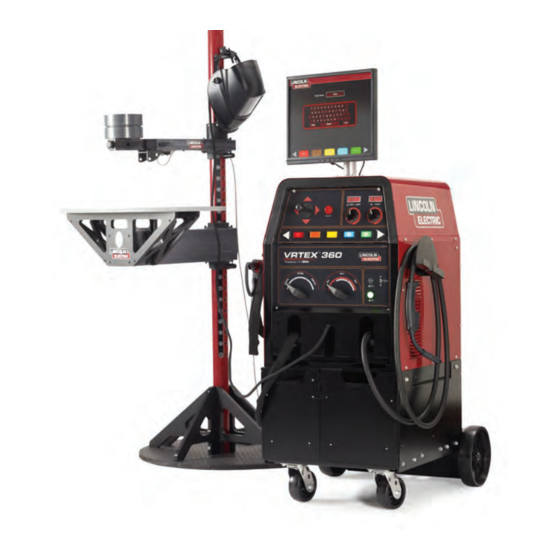
OPERATION PRODUCT DESCRIPTION The VRTEX 360 is a virtual reality arc welding train- Access panels are not to be removed except by quali- ing machine only and NOT a real arc welding fied service personnel due to risk of electric shock machine. -
Page 19: User Interface Overview
OPERATION USER INTERFACE OVERVIEW 10. The key switch is located on the lower right of the control panel. When the system is in the login The VRTEX 360 is a virtual reality arc welding train- screen the instructor may insert the key shipped er. - Page 20 OPERATION HARDWARE SPECIFICS: In order to strike an arc with the VR SMAW device, strike or tap the tip of the rod (of the VR SMAW device) on the coupon being welded. To break the VR GMAW/FCAW GUN arc, move the VR SMAW device rod away from the The VR gun has a trigger that is used during the simu- work piece.
- Page 21 When not in use, the helmet should be hung from the stand or placed in the right front drawer to avoid being damaged. The coupons along with the VR SMAW device and VR GMAW/FCAW gun have been factory calibrated at Lincoln Electric. VRTEX...
- Page 22 OPERATION Stand SWING ARM ROTATION The stand is comprised of the post, arm, table, collar pins, base and two weights. Users should position POS. A POS. C themselves at the stand during virtual welding. Post The arm and table slide up and down and rest on the collar pins that are inserted into the post.
-
Page 23: Powering Up
VR GMAW) within the ranges set in the tolerance edi- tor. The system ships with Lincoln default tolerances. Lincoln default tolerances can be reviewed in the tol- erance editor, or refer to the Default Weld Process Settings Chart (if using the default settings) located at the end of this OPERATION SECTION. - Page 24 OPERATION Login Screen: Press the red select button to accept. Press the yellow button again to exit the language Overview menu. The system stores the language selection and This page allows the user to: will automatically start up in the same language the •...
- Page 25 OPERATION Joint Configuration Selection JOINT CONFIGURATION SELECTION SCREEN Screen: Overview The user selects which joint configuration they want to virtually weld. First, the user selects the joint and position. Using the joystick and the red select button, the user highlights and selects the joint type and posi- tion in which to weld.
- Page 26 OPERATION Process Selection Screen: Stand Set-Up Screen: Overview Overview The correct VR stand information must be put into This screen allows the user to select the welding the software for the VRTEX 360 to operate prop- processes. To change among VR GMAW, VR FCAW, erly in all virtual welding applications.
- Page 27 B-10 B-10 OPERATION Table/Arm Rotation Pin Positions Move the physical VR table and arm to the desired When the physical stand is in the desired position, location for the position and joint configuration select- proceed with the following: Use the joystick and red ed.
- Page 28 B-11 B-11 OPERATION Indicate the coupon orientation used on the physical ENVIRONMENT SCREEN stand in the coupon rotation area of the stand setup screen. The red arrow indicates which side of the coupon that the weld will be made. For pipe configu- rations, the coupon rotation is replaced with arm angle.
- Page 29 B-12 B-12 OPERATION Weld Machine Settings Screen: Once the user has set the welding parameters, they should press the green check settings button. If the Overview user has entered any settings outside the acceptable The user must enter the proper welding procedure range specified by the settings in the tolerance editor, and process settings, including wire feed speed, the incorrect weld setting screen will appear.
-
Page 30: Push Buttons
B-13 B-13 OPERATION Upper Overlays Generally, these cues are color coded as well as sym- bolic. When cues are red, they indicate being out of The welding technique set in the tolerance editor and tolerance. Yellow cues indicate close to tolerance, but other process details are displayed on the upper right not optimal. -
Page 31: Travel/Work Angle
B-14 B-14 OPERATION The Arc Length cue is similar to the CTWD cue but The Whip cue can be used with the E6010 VR SMAW represents arc length distance for the VR SMAW process. This cue helps the student use correct spac- process. -
Page 32: Welders View
B-15 B-15 OPERATION LASER SCREEN New Coupon (Live Action Student Evaluation Report) Pressing the blue new coupon menu button instantly replaces the current coupon with a fresh, unwelded Overview coupon. Note that this is a quick way to start over on This screen summarizes the student’s welding perfor- the same configuration and process but that it will mance. -
Page 33: Technique Parameters
B-16 B-16 OPERATION LASER SCREEN (GRAPH, DEFECTS, DISCONTINUITIES, ETC.) TECHNIQUE PARAMETERS The upper left area of the screen shows the technique parameters being tracked and the graph of these parame- ters is located to the right. When the user welds, each parameter is graphed using a line that is of the same color as the technique parameter box. -
Page 34: Position
B-17 B-17 OPERATION Position is the user’s ideal weld root location. This Travel Angle is the angle between the electrode and location can change with each pass. When weaving, the workpiece in the direction of travel. The upper right the ideal location is considered the centerline of the area of the screen displays if the user should be push- weave. - Page 35 B-18 B-18 OPERATION Travel Speed is how fast the electrode is traveling in Bead Render respect to the workpiece. An image of the completed pass appears in the mid- dle of the screen. Dime Spacing is the distance from one solidified weld puddle to the next.
-
Page 36: Instructor Mode
B-19 B-19 OPERATION End Pass INSTRUCTOR MODE When the user presses the green “End Pass” menu button, the pass is scored, a snapshot of the weld is taken, and the percentages of the weld containing dis- continuities are calculated. If the user has inserted a USB device, pressing “End Pass”... - Page 37 B-20 B-20 OPERATION Weldometer Overview The Weldometer tracks virtual consumables, base material and gas usage. This information can be used to track materials and cost savings incurred by the use of virtual welding training. The Weldometer tracks material usage and arc time over a “trip” (since last reset) and over the VR system’s lifetime. Arc Time keeps track of the amount of time (hours:min:seconds) students have a virtual arc struck with each process.
-
Page 38: Tolerance Editor
Save to File The VRTEX 360 ships with Lincoln “default” welding If a USB memory device is in the front of the unit, parameters pre-installed. The parameters can be selecting “save to file” saves a file with all of the cur-... -
Page 39: Choosing Tolerance Set-Up
B-22 B-22 OPERATION Choose Tolerance Set-up USB Edit This displays the list of all tolerance settings currently stored on the unit. All units ship with default settings. This menu relates only to the files on the USB memo- If the user creates multiple tolerance files, the file in ry device. - Page 40 B-23 B-23 OPERATION TOLERANCES SELECTED (DEFAULTS) Back Pressing Back goes back to the previous screen. Continue Pressing Continue goes to the tolerance process selection screen. Tolerances Process Selection Screen Overview The user selects which process to modify. TOLERANCES PROCESS SELECTION SCREEN Back Pressing back returns the user to the previous page screen.
- Page 41 B-24 B-24 OPERATION Next Pass Modifying Tolerances The next pass button changes the pass being modi- Overview fied to the next pass in the series. If this is the last The user can modify the tolerance values. This is pass, this option will not be available. done by: 1) Use the joystick to highlight the equipment setting Tolerances Equipment Settings...
- Page 42 B-25 B-25 OPERATION Tolerances Welding Technique Tolerances Pattern and Aim Screen Parameters Screen Overview This screen allows the user to change the type of pat- Overview tern being used (stringer, box weave, straight weave, This screen allows the modification of: whip, triangle weave) and the position of the root of •...
-
Page 43: Tolerances Whip & Travel Speed
B-26 B-26 OPERATION Tolerances Whip and Travel Speed Screen Overview This screen allows for the modification of technique parameter relating to the whipping welding technique and travel speed including: • Dime Spacing • Whip Time • Puddle Time • Travel Speed WHIP &... - Page 44 G a s F l o w ( c f h ) L i n c o l n B r a n d G a s M i x t u r e VRTEX 360 - Default Weld Process Settings VR Welding Consumable Gas Flow...
-
Page 45: Maintenance
MAINTENANCE CLEANING & MAINTENANCE Taking proper care of the FMD (Face Mounted Display) is important for optimal functioning of the equipment. Occasionally, the FMD lens should be wiped with the lint free lens wipe that is provided. This can be done to remove fingerprints from the lens- es. -
Page 46: Troubleshooting
HOW TO USE TROUBLESHOOTING GUIDE WARNING Service and Repair should only be performed by Lincoln Electric Factory Trained Personnel. Unauthorized repairs performed on this equipment may result in danger to the technician and machine operator and will invalidate your factory warranty. For your safety and to avoid Electrical Shock, please observe all safety notes and precautions detailed throughout this manual. -
Page 47: Wiring Diagrams
Check for loose or faulty connections Helmet display and Monitor. work piece. The further the helmet between the Helmet/Monitor and the is from the work piece the more jitter VRTEX 360 machine. See the there may be in the helmet display. wiring diagram. Local interference. - Page 48 Again figurations only have one pass capa- “End Pass” must be pressed before bilities. See the Lincoln default tol- a new pass is started erances. Some or none of the welding para- These items may be “toggled” off.
- Page 49 DIAGRAMS VRTEX...
- Page 50 NOTES VRTEX...
-
Page 51: Parts
Do not touch electrically live parts or Keep flammable materials away. Wear eye, ear and body protection. • • • WARNING electrode with skin or wet clothing. Insulate yourself from work and • ground. Spanish No toque las partes o los electrodos Mantenga el material combustible Protéjase los ojos, los oídos y el •... - Page 52 Keep your head out of fumes. Turn power off before servicing. Do not operate with panel open or • • • WARNING Use ventilation or exhaust to guards off. • remove fumes from breathing zone. Spanish Los humos fuera de la zona de res- •...
- Page 53 • World's Leader in Welding and Cutting Products • • Sales and Service through Subsidiaries and Distributors Worldwide • Cleveland, Ohio 44117-1199 U.S.A. TEL: 216.481.8100 FAX: 216.486.1751 WEB SITE: www.lincolnelectric.com...
Need help?
Do you have a question about the Vrtex 360 and is the answer not in the manual?
Questions and answers