Table of Contents
Advertisement
Quick Links
Lincoln welders are designed and built with safety in mind. However, your overall safety can be increased
by proper installation . . . and thoughtful operation on your part. Read and observe the general safety
precautions on page 2 and follow specific installation and operating instructions included in this manual.
Most importantly, think before you act and be careful.
(AUSTRALIA) PTY. LTD.
Associated Subsidiaries in Australasia, Asia, Canada, Europe, North and South America.
THE WORLD'S LEADER IN WELDING AND CUTTING PRODUCTS
OPERATING MANUAL
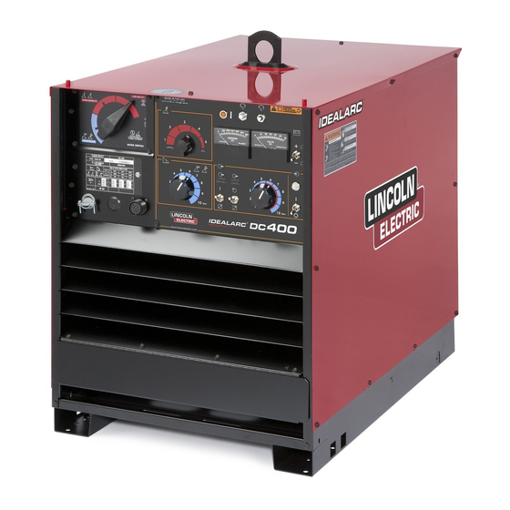
IDEALARC
DC-400
(For Codes 1386 to 1462)
SAFETY DEPENDS ON YOU
SYDNEY. AUSTRALIA
A Subsidiary of
THE LINCOLN ELECTRIC CO. U.S.A.
A.B.N. 36 000 040 308
IMA 474A
June 1999
Advertisement
Table of Contents

Related Manuals for Lincoln IDEALARC DC-400


Summary of Contents for Lincoln IDEALARC DC-400
- Page 1 (For Codes 1386 to 1462) SAFETY DEPENDS ON YOU Lincoln welders are designed and built with safety in mind. However, your overall safety can be increased by proper installation . . . and thoughtful operation on your part. Read and observe the general safety precautions on page 2 and follow specific installation and operating instructions included in this manual.
- Page 2 PROTECT YOURSELF AND OTHERS FROM POSSIBLE SERIOUS INJURY OR DEATH. READ AND UNDERSTAND BOTH THE SPECIFIC INFORMATION GIVEN IN THE OPERATING MANUAL FOR THE WELDER AND/OR OTHER EQUIPMENT TO BE USED AS WELL AS THE FOLLOWING GENERAL INFORMATION. ARC WELDING SAFETY PRECAUTIONS ARC RAYS can burn ELECTRIC SHOCK can kill 1.
- Page 3 Note: “Hardware” in the Lincoln Parts Lists are not Lincoln stock items but can be obtained via the Authorised Service Facilities. Component parts of assemblies such as stator coils or armature coils, etc., which require electrical testing or locating fixtures are not considered replaceable items.
- Page 4 WELDING, EMF & PACEMAKERS Welders with pacemakers All welders should follow safe practices that minimise their exposure to electric and magnetic fields (EMF). There is no question that the fields in arc welding can For welders wearing implanted pacemakers, safe welding interfere with a pacemakers function.
-
Page 5: Mains Supply
Maintenance of the Welding Equipment Products are: The welding equipment should be routinely maintained according • for use with other Lincoln Electric/LiquidArc equipment. to the manufacturer’s recommendations. All access and service • designed for industrial and professional use. doors and covers should be closed and properly fastened when Introduction the welding equipment is in operation. - Page 6 MEANINGS OF GRAPHIC SYMBOLS The DC-400 nameplate has been designed to use international symbols in describing the function of the various components. Below are the symbols used. POWER ON-OFF SWITCH CIRCUIT BREAKER Circuit Breaker Input (Power) THERMAL PROTECTION LIGHT High Temperature OUTPUT CONTROL DIAL Output (Control) ARC CONTROL SWITCH...
- Page 7 VOLTMETER SWITCH OUTPUT TERMINALS SWITCH Voltmeter Output (Voltage) Positive Electrode Negative Electrode Remote On/Off RATING PLATE ARC FORCE CONTROL DIAL Three Phase Power Shielded Metal Arc Welding Transformer Gas Tungsten Arc Welding Rectifier Arc Force Current Rectified DC Output Increase/Decrease of Current Constant Voltage Characteristic –...
- Page 8 RATING PLATE (Continued) Three Phase Power Transformer Rectifier Rectified DC Output Constant Voltage Characteristic Constant Current Characteristic Line Connection Shielded Metal Arc Welding Flux Cored Arc Welding Submerged Arc Welding IP21 Degree of protection provided by the enclosure Page 8 DC-400 IMA 474...
- Page 9 MODE SWITCH Do not switch if output voltage or current is present. Constant Voltage (Submerged Arc Welding) Constant Voltage (Flux cored arc welding, gas metal arc welding). Constant Current (shield metal arc welding, gas tungsten arc welding). WARNING IDENTIFICATION Warning Identification EARTH CONNECTION Signifying the Earth Connection IMA 474...
-
Page 10: General Machine Description
GENERAL MACHINE DESCRIPTION VOLTMETER SWITCH “+” ELECTRODE OR “-” ELECTRODE The DC-400 is an SCR controlled three phase DC power source. It is designed with a single range potentiometer This switch selects electrode polarity for the remote (#21) control. work sensing lead of automatic or semiautomatic equipment. - Page 11 INPUT LINE VOLTAGE COMPENSATION The case rear, top section, is equipped with a removable access panel. This provides easy access to the input The power source is equipped with input line voltage contactor, easy connection and reconnection of input compensation as standard. For a line voltage fluctuation of leads, and easy access for service or inspection.
-
Page 12: Optional Equipment
Machine & Circuit Protection An optional “remote output control” is available. This is the same remote control that is used on the Lincoln R3R, and (Thermal Protection Light) DC-600 power sources (K775). The K775 consists of a control box with 8.5m of four conductor cable. -
Page 13: Technical Specifications
OPTIONAL AMPTROL ADAPTER FOR K799-1 HI- 2) DC-400 is used with an LN-22 equipped with an older K279 Contactor-Voltage Control Option. Eliminates FREQUENCY KIT (K915-1 REQUIRES K864 electrode overrun when gun trigger is released. Not ADAPTER OR K843 ADAPTER) required when later K279 (above Code 8800) is used. A “V”... - Page 14 INSTALLATION LIMIT ON STACKING WARNING Safety Precautions WARNING FALLING EQUIPMENT can cause injury • Do not touch electrically live parts • Do not lift this machine using lift bale if it is equipped with or electrode with skin or wet a heavy accessory such as as undercarriage trailer or clothing.
- Page 15 See Amptrol Adapter Installation Instructions on next page. connector on the machine. An optional “remote output control” is available. This is the same remote control that is used on the Lincoln R3R, and K930-2 TIG Module DC-600 power sources (K775). The K775 consists of a control box with 8.5m of four conductor cable.
- Page 16 Lincoln wire feeder being A strain relief box connector is provided for access into the used. “Electrode” and “Work” are connected to the left terminal strip section.
-
Page 17: Operating Instructions
NOTE: If both stick and semiautomatic welding are to be OPERATING INSTRUCTIONS done on the same workpiece, it is not necessary to have Safety Precautions separate work cables for stick and semiautomatic welding WARNING and only one work lead is required. To do this, connect a 95mm jumper from... -
Page 18: Power Source Operation
POWER SOURCE OPERATION the machine, or by connecting a K857 control to the 14-pin connector on the front of the machine. For control at the WARNING machine control panel, the toggle switch is set in the “LOCAL” position. (Exception: When used with an LN-9, LN-9 GMA or NA-5 wire feeder, the OUTPUT CONTROL switch must be in the “REMOTE”... - Page 19 ARC FORCE CONTROL DIAL Lead No. Function (Effective only in CC) 110 - 115V AC The ARC FORCE control is calibrated from one to ten. For Chassis Connection most welding, the dial should be set at approximately mid- Trigger Circuit range, 5-6.
-
Page 20: Troubleshooting
MAINTENANCE WARNING ELECTRIC SHOCK can kill • Have an electrician install and service this equipment. • Turn the input power off at the fuse box before working on equipment. • Do not touch electrically hot parts. Routine Maintenance 1. The fan motor has sealed bearings which require no service. - Page 21 TROUBLESHOOTING TROUBLE CAUSE WHAT DO DO A. Input contactor (CR1) chatters. 1. Faulty input contactor (CR1). 1. Repair or replace. 2. Low line voltage. 2. Check input power. B. Machine input contactor does 1. Supply line fuse blown. 1. Replace if blown - look for reason not operate.
- Page 22 TROUBLESHOOTING (continued) TROUBLE CAUSE WHAT DO DO G. Machine does not have 1. One input fuse blown. 1. Check and replace if blown after maximum output. checking for reason for blown fuse. 2. Open phase of main transformer 2. Check for open repair. open.
- Page 23 TROUBLESHOOTING (continued) TROUBLE CAUSE WHAT DO DO L. Poor arc striking with 1. Defective start circuit. 1. Check Start PC Board and reed semiautomatic or automatic switch CR3. wire feeders. 2. Poor work connection. 2. Work connection must be adequate for application.
- Page 24 PROCEDURE FOR REPLACING PC BOARDS CHECKING SNUBBER CIRCUIT WARNING In case of an SCR malfunction or failure the snubber assembly should be checked. Turn the machine off and remove the sides of the machine. (See the instruction manual parts list for the exact location). Visually inspect the snubber assembly for overheated ELECTRIC SHOCK can kill components or damaged components.
- Page 25 Power Rectifier Bridge Assembly Checking Procedure WARNING ELECTRIC SHOCK can kill • Have an electrician install and service this equipment.. • Turn the input power off at the fuse box before working on equipment. • Do not touch electrically hot parts. 1.
- Page 26 ‘MEGA’ tester to the input contactor jumper to be ‘adjusted’ to suit these modifications. and the other lead to: For prompt service contact your local authorised Lincoln a) lead No. 32A field service shop. b) lead No. 233A The insulation resistance values listed below are from c) lead No.
- Page 27 AP-234 Operative: 1.4.99 Supersedes: Parts List for DC-400 IMA 474 DC-400 Page 27...
- Page 28 AP-234-A Operative: 1.4.99 Supersedes: Illustration of Sub-Assemblies Page 28 DC-400 IMA 474...
- Page 29 DC-400 For Codes: 1386 To 1462 Do not use this Parts List for a machine if its code number is not listed. Contact an authorised Lincoln/LiquidArc Field Service Shop for any code numbers not listed . Use the Illustration of Sub-Assemblies page and the table below to determine which sub assembly page and column the desired part is located on for your particular code machine.
- Page 30 DC-400 For Codes: 1386 To 1462 Do not use this Parts List for a machine if its code number is not listed. Contact an authorised Lincoln/LiquidArc Field Service Shop for any code numbers not listed. Use the Illustration of Sub-Assemblies page and the table below to determine which sub assembly page and column the desired part is located on for your particular code machine.
- Page 31 AP-234-B Operative: 1.4.99 Supersedes: Optional Equipment Listing Miscellaneous options available for your machine are listed below: Description Part No. Remote Output Control ............K775 Hi-Freq .
- Page 32 AP-234-C Operative: 1.4.99 Supersedes: Case Front Assembly 17C 17D 17E 24D 24E Part of Wiring Harness Part of 15A Part of 12A LINC.DC400-2 Page 32 DC-400 IMA 474...
- Page 33 AP-234-C1 Operative: 1.4.99 Supersedes: Item Description Part No. Case Front Welded Assembly AL2217-2 Control Box AL2216-1 Air Deflector S18375 Self Tapping Screw AS1733-3Z Air Deflector S17353 Louvre M15391-2 Louvre M15391-3 Output Panel AM3016 Self Tapping Screw Output Stud Cover Assembly M17097 Self Tapping Screw Self Tapping Screw...
- Page 34 AP-234-D Operative: 1.4.99 Supersedes: Fan Baffle & Reconnect Panel Part of 3A 10D 10E 10F Part of 3A Part of 1G LINC.DC400-5 Page 34 DC-400 IMA 474...
- Page 35 AP-234-D1 Operative: 1.4.99 Supersedes: Item Description Part No. Fan Baffle Assembly includes: M16526-3 Fan Baffle L6247 Self Tapping Screw Fan Motor M9983-6 Plain Washer #10-32 Hex Nut (or) #8-32 Hex Nut M6819-9 Fan Motor Mounting Bracket M16525 Self Tapping Screw (not shown) Input Box Assembly S16815 Reconnect Panel Assembly, includes: (Multi Voltage)
- Page 36 AP-234-E Operative: 1.4.99 Supersedes: Rectifier Bridge Assembly 13A 13B 13C 13A 13B 13C 13A 13B 13C Page 36 DC-400 IMA 474...
- Page 37 AP-234-E1 Operative: 1.4.99 Supersedes: Item Description Part No. 3 Phase Rectifier Bridge Assembly (complete) AL2350 Heat Sink (D.C. Negative) L7519 Heat Sink (D.C. Positive) L7518 Baffle S18366 Carriage Bolt T11827-31 Insulating Bushing S16860 Insulating Tube T7028-141 Plain Washer 1/4-20 Hex Nut Shunt Strap S11109-6 5/16-18 x 1.25 Hex Head Cap Screw...
- Page 38 AP-234-F Operative: 1.4.99 Supersedes: Transformer & Lift Bale Assembly 13A 13B 12A 12B 12C Page 38 DC-400 IMA 474...
- Page 39 AP-234-F1 Operative: 1.4.99 Supersedes: Item Description Part No. Transformer Assembly See AP234-H Choke Coil Assembly L7524-1 Plain Washer Lock Washer 5/16-18 Hex Nut Base Welded Assembly AM2808-2 Capacitor Baffle S17358 Thread Forming Screw Choke Baffle S17357 Thread Forming Screw Resistor (R1) S10404-96 #10-24 x 7.50 Round Head Screw Insulating Washer...
- Page 40 AP-234-G Operative: 1.4.99 Supersedes: Control Box Cover Assembly 13B 13C 13D 6A 6B 4C 4B Part of 10 Part of Meter 18A 22B Part of 22A LINC.DC400-3 Page 40 DC-400 IMA 474...
- Page 41 AP-234-G1 Operative: 1.4.99 Supersedes: Item Description Part No. Micro Switch Bracket (see assembly) Micro Switch Assembly S18381 Switch Actuator T14797 Round Head Screw Lock Washer Hex Nut T14799 Set Screw Terminal Strip S8542-7 Self Tapping Screw Terminal Strip S14530-12 Self Tapping Screw Number Plate S18378-1 Terminal Strip Bracket...
- Page 42 AP-234-H Operative: 1.4.99 Supersedes: Coil Assemblies LEFT RIGHT BOTTOM Page 42 DC-400 IMA 474...
- Page 43 AP-234-H1 Operative: 1.4.99 Supersedes: Item Description Part No. Transformer Assembly (Code 1386, 1449, 1462) AG1334-3 Transformer Assembly (Code 1415) AG1334-1 NOTE: When replacing Primary Coils Code 1386 - order complete set. (Includes 1 through 9) Primary Coil (Top/Left) Codes 1386, 1449, 1462) 9857-52 Primary Coil (Top/Left) (Code 1415) 9852-52...
- Page 44 AP-234-J Operative: 1.4.99 Supersedes: Roof & Sides Item Description Part No. Roof (Code 1462 uses - 10U) AM2805-10 Side Panel (Code 1462 uses - 1U) AM2804-1 Self Tapping Screw AS1733-3Z Cover Seal S12934 Warning Decal T13086-20 Warning Decal (Europe) L8064-1 Caution Decal (Back side of panel) (not shown) S13504 Page 44...
- Page 45 AP-234-K Operative: 1.4.99 Supersedes: Diode Option L9286 Item Description Part No. Diode Option Assembly, includes (1 through 12) L9286 Heat Sink S20943 Rectifier Diode M9661-36 Spring Washer T12735 Mounting Angle S21239 Carriage Bolt T11827-39 Lock Washer Plain Washer Lock Washer 5/16-18 Hex Nut Connection Lead S20945...
- Page 46 AP-234-L Operative: 1.4.99 Supersedes: POWER RECTIFIER BRIDGE DIAGRAM 1 PLUG TO SNUBBER BOARD ANODE To (+) side of capacitor bank CATHODE ANODE SCR1 SCR2 SCR3 GATE CATHODE SHUNT mode switch Gate leads plug to control P.C. board To plug To T1 main transformer Page 46 DC-400...
- Page 47 WIRING DIAGRAM Ref: AL2460 (A26.6.96) NOTE: This diagram is for reference only. It may not be accurate for all machines covered by this manual. The specific diagram for a particular code is pasted inside the machine on one of the enclosure panels. If the diagram is illegible, write to the Customer Service Department for a replacement.
- Page 48 CAUTION INPUT SUPPLY CONNECTION DIAGRAM 220 / 380 / 440 All input power must be electrically disconnected before touching panel. Note: Machines are shipped from factory connected for highest voltage. Connection for 400V 50Hz (460V 60Hz) On reconnect panel, loosen all hex bolts, pull back movable links and rotate links to their new positions.
- Page 49 AP-239 Operative: 1.4.99 Supersedes: Multi-Process Switch K804-1 Do Not use this Parts List for a machine if its code number is not listed. Contact the Customer Service Department for any code numbers not listed. Use the Illustration of Sub-Assemblies page and the table below to determine which sub assembly page and column the desired part is located on for your particular code machine.
- Page 50 AP-239-C Operative: 1.4.99 Supersedes: Multi-Process Switch L6203-1 Page 50 DC-400 IMA 474...
- Page 51 AP-239-C1 Operative: 1.4.99 Supersedes: Item Description Part No. Front & Top Cover AL2462 Self Tapping Screw Nameplate M13892 Process Switch L3545-22 Lock Washer 1/4-20 Hex Nut 5/16-18 Hex Nut Negative Lead Strap S16649 1/2-13 x 1.00 Hex Head Cap Screw Plain Washer Lock Washer Plain Washer...
-
Page 52: Limited Warranty
Lincoln ® may at its absolute discretion repair or replace the goods F.O.B. at its own premises or at such other premises as Lincoln ® Three Years* may designate provided that all freight charges to and from Lincoln's premises or such...
Need help?
Do you have a question about the IDEALARC DC-400 and is the answer not in the manual?
Questions and answers