Table of Contents
Advertisement
Operator's Manual
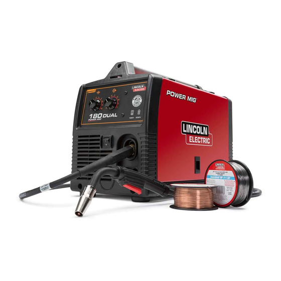
POWER MIG
Register your machine:
www.lincolnelectric.com/register
Authorized Service and Distributor Locator:
www.lincolnelectric.com/locator
Save for future reference
Date Purchased
Code: (ex: 10859)
Serial: (ex: U1060512345)
IM890-A
| Issue D ate Nov- 13
© Lincoln Global, Inc. All Rights Reserved.
®
(140, 180 MODELS)
For use with machines having Code Numbers:
11254, 11255, 11256, 11257 and
11444
Advertisement
Table of Contents


Need help?
Do you have a question about the POWER MIG 140 and is the answer not in the manual?
Questions and answers