Table of Contents
Advertisement
For use with machine Code Numbers: 10562, 10952, 10958, 11000, 11097, 11098
This manual covers equipment which is no
longer in production by The Lincoln Electric Co.
Speci cations and availability of optional
features may have changed.
Safety Depends on You
Lincoln arc welding and cutting
equipment is designed and built
with safety in mind. However, your
overall safety can be increased by
proper installation ... and thought-
ful operation on your part. DO
NOT INSTALL, OPERATE OR
REPAIR THIS EQUIPMENT
WITHOUT
READING
THIS
MANUAL AND THE SAFETY
PRECAUTIONS CONTAINED
THROUGHOUT. And, most
importantly, think before you act
and be careful.
• Sales and Service through Subsidiaries and Distributors Worldwide •
Cleveland, Ohio 44117-1199 U.S.A. TEL: 216.481.8100 FAX: 216.486.1751 WEB SITE: www.lincolnelectric.com
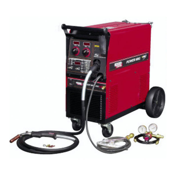
POWER MIG
For use with machine
OPERATOR'S MANUAL
• World's Leader in Welding and Cutting Products •
300
™
Copyright © 2004 Lincoln Global Inc.
IM736-D
February, 2004
Advertisement
Table of Contents
Troubleshooting

Related Manuals for Lincoln POWER MIG 300


Summary of Contents for Lincoln POWER MIG 300
- Page 1 For use with machine Code Numbers: 10562, 10952, 10958, 11000, 11097, 11098 For use with machine This manual covers equipment which is no longer in production by The Lincoln Electric Co. Speci cations and availability of optional features may have changed.
-
Page 2: California Proposition 65 Warnings
351040, Miami, Florida 33135 or CSA Standard W117.2-1974. A Free copy of “Arc Welding Safety” booklet E205 is available from the Lincoln Electric Company, 22801 St. Clair Avenue, Cleveland, Ohio 44117-1199. BE SURE THAT ALL INSTALLATION, OPERATION, MAINTENANCE AND REPAIR PROCEDURES ARE PERFORMED ONLY BY QUALIFIED INDIVIDUALS. -
Page 3: Electric Shock Can Kill
SAFETY ELECTRIC SHOCK can ARC RAYS can burn. kill. 4.a. Use a shield with the proper filter and cover plates to protect your eyes from sparks and 3.a. The electrode and work (or ground) circuits the rays of the arc when welding or observing are electrically “hot”... - Page 4 SAFETY WELDING SPARKS can CYLINDER may explode cause fire or explosion. if damaged. 6.a. Remove fire hazards from the welding area. 7.a. Use only compressed gas cylinders If this is not possible, cover them to prevent containing the correct shielding gas for the the welding sparks from starting a fire.
- Page 5 SAFETY 5. Toujours porter des lunettes de sécurité dans la zone de PRÉCAUTIONS DE SÛRETÉ soudage. Utiliser des lunettes avec écrans lateraux dans les zones où l’on pique le laitier. Pour votre propre protection lire et observer toutes les instructions et les précautions de sûreté...
- Page 6 The code number is especially important when identifying the correct replacement parts. On-Line Product Registration - Register your machine with Lincoln Electric either via fax or over the Internet. • For faxing: Complete the form on the back of the warranty statement included in the literature packet accompanying this machine and fax the form per the instructions printed on it.
-
Page 7: Table Of Contents
Definition Of Welding Modes....................B-1 Common Welding Abbreviations ..................B-1 Product Description ......................B-2 Controls and Settings ....................B-2, B-3 Setting and Configuring the POWER MIG 300 for welding ..........B-4 Multi-Process Panel Functions ..................B-5, B-6 Wire Drive Roll ........................B-7 Procedure for Changing Drive and Idle Roll Sets..............B-8 Wire Reel Loading........................B-8... -
Page 8: Installation
INSTALLATION TECHNICAL SPECIFICATIONS – POWER MIG 300 INPUT – SINGLE PHASE ONLY Standard Voltage/Frequency Input Current @ 230Amp Rated Output Input Current @ 300 Amp Rated Output 208/230/460/575/60 Hz 48/43/22/17 Amps 72/62/31/25 Amps RATED OUTPUT Input Voltage Duty Cycle Amps... -
Page 9: Safety Precautions
• Use ventilation or exhaust to remove fumes from breathing 2. The POWER MIG 300 is supplied connected for zone and general area. 230 Volt Input. If the welder is to be operated on... - Page 10 A green wire in the input THREE PHASE SYSTEM. cable connects this contact to the frame of the welder. This ensures proper grounding of the welder frame when the welder plug is inserted into the receptacle. POWER MIG 300...
-
Page 11: Gun And Cable Installation
(12Ft.(3.7m) for Codes 11000 and below) are provid- (inside wire feed compartment) until tip of screw no ed with the POWER MIG 300. A Magnum cable liner longer protrudes into gun opening as seen from for .035-.045" (0.9-1.2 mm) electrode and contact tips front of machine. - Page 12 5. Attach one end of the inlet gas hose to the outlet fitting of the flow regulator, the other end to the POWER MIG 300 rear fitting, and tighten the union nuts securely with a wrench. 6. Before opening the cylinder valve, turn the regula- tor adjusting knob counterclockwise until the adjusting spring pressure is released.
-
Page 13: Operation
OPERATION Read entire Operation section before COMMON WELDING ABBREVIA- operating the POWER MIG 300. TIONS WARNING ELECTRIC SHOCK can kill. • Wire Feed Speed • Do not touch electrically live parts or electrode with skin or wet clothing. Insulate yourself •... -
Page 14: Product Description
3/64 aluminum with the The POWER MIG 300 is a complete semiautomatic standard POWER MIG 300 gun and wire feeder. A multi-process DC arc welding machine offering CV Dual Cylinder Mounting Kit is also offered. - Page 15 • When there is no output, the meter will display "OFF." machine. The most commonly used modes are dis- played in the chart on the right half of the Multi- 3. OUTPUT CONTROLS - The POWER MIG 300 has 2 Process Panel. encoder knobs to adjust weld parameters.
-
Page 16: Setting And Configuring The Power Mig 300 For Welding
The weld parameters are detailed later in this section. FIGURE B.2 TABLE B.1 PREFLOW / RUN IN START ARC CONTROL CRATER BURNBACK SPOT POSTFLOW CC-STICK ----- ----- ----- ----- ----- CC-GTAW ----- ----- ----- ----- ----- CV-FCAW ----- CV-GMAW CV-GMAW-P POWER POWER MIG 300... -
Page 17: Multi-Process Panel Functions
After setting the Start time also set the WFS, and second increments. voltage/trim. The way to know what information needs to be entered is to look for flashing LED’s. If an LED is flashing that parameter value needs to be entered. POWER MIG 300... - Page 18 Minus settings result in (Aluminum Only) array control lower array frequency a wider bead with more and the plus settings distinct ripples. Plus increase the array settings narrow the frequency. resultant bead and the ripples are less distinct. POWER MIG 300...
-
Page 19: Wire Drive Roll
WFS and Voltage that will be reached over a specified time period. At the end of the weld when the trigger is The drive rolls installed with the POWER MIG 300 have two released, the crater timer will begin and the WFS and grooves, one side for .030"... -
Page 20: Procedure For Changing Drive And Idle Roll Sets
Release Bar “pops up” and that the collar retainers in lining up a hole). Be certain the wire comes off fully engage the retaining ring groove on the spin- the reel in a direction so as to de-reel from the top dle. of the coil. POWER MIG 300... -
Page 21: Feeding Wire Electrode
(over the drive roll groove). Push a sufficient wire length to assure that the wire has fed e. Use only clean, rust-free electrode. Lincoln elec- into the gun and cable assembly without restriction. trodes have proper surface lubrication. -
Page 22: Special Welding Processes Available
Pulsed MIG is an advanced form of welding that takes the best of all the other forms of transfer while minimiz- AVAILABLE ON THE POWER MIG 300 ing or eliminating their disadvantages. Unlike short cir- cuit, pulsed MIG does not create spatter or run the risk of cold lapping. - Page 23 When Arc Control is used in the Pulse on Pulse modes, it does the same things it does in the other Pulse on Pulse™ is a Lincoln process specifically pulsed modes: decreasing the Arc Control decreases designed for use in welding relatively thin (less than the droplet transfer and weld deposition rate.
-
Page 24: Power Mode
Start by setting the wire feed speed based upon mate- The Power Mode™ process was developed by rial thickness and appropriate travel speed. Then Lincoln to maintain a stable and smooth arc at low adjust the Volts/Trim knob as follows: procedure settings which are needed to weld thin metal without pop-outs or burning-through. -
Page 25: Accessories
(Magnum 300): Disables spool gun operation. • The K363P Readi-Reel Adapter mounts to the 2" Changes the displays of the POWER MIG 300 to • spindle. It is needed to mount the 22-30 lb. Readi- correspond to feeder gun operation. -
Page 26: Push-Pull Feeding Connection Adapter Kit
The actual wire feed speed (WFS) of the spool gun must be measured and manually set on the CAUTION POWER MIG 300 as a work point for the POWER MIG 300 (SPD). Remove all input power to the POWER MIG 300 In synergic modes when the spool gun trigger is •... -
Page 27: Maintenance
Remove the cable from the wire feeder and lay it out straight on the floor. Remove the contact tip from the gun. Using an air hose and only partial pres- sure, gently blow out the cable liner from the gas dif- fuser end. POWER MIG 300... -
Page 28: Liner Removal And Replacement
GUN TUBE BRASS CABLE CONNECTOR 9/16 (14.3mm) MOLDED GAS PLUG SET SCREW LINER TRIM CLAMPING SCREW LENGTH SET SCREW GAS DIFFUSER LINER ASSEMBLY (LINER BUSHING TO BE SEATED NOZZLE INSULATION TIGHT AGIANST BRASS CABLE CONNECTOR) GAS NOZZLE POWER MIG 300... - Page 29 TROUBLESHOOTING WARNING Service and Repair should only be performed by Lincoln Electric Factory Trained Personnel. Unauthorized repairs performed on this equipment may result in danger to the technician and machine operator and will invalidate your factory warranty. For your safety and to avoid Electrical Shock, please observe all safety notes and precautions detailed throughout this manual.
-
Page 30: Troubleshooting
CAUTION If for any reason you do not understand the test procedures or are unable to perform the tests/repairs safely, contact your Local Lincoln Authorized Field Service Facility for technical troubleshooting assistance before you proceed. POWER MIG 300... -
Page 31: Troubleshooting
CAUTION If for any reason you do not understand the test procedures or are unable to perform the tests/repairs safely, contact your LOCAL AUTHORIZED LINCOLN ELECTRIC FIELD SERVICE FACILITY for assistance before you proceed. POWER MIG 300... - Page 32 5. Check spindle for ease of rotation. CAUTION If for any reason you do not understand the test procedures or are unable to perform the tests/repairs safely, contact your LOCAL AUTHORIZED LINCOLN ELECTRIC FIELD SERVICE FACILITY for assistance before you proceed. POWER MIG 300...
- Page 33 CAUTION If for any reason you do not understand the test procedures or are unable to perform the tests/repairs safely, contact your LOCAL AUTHORIZED LINCOLN ELECTRIC FIELD SERVICE FACILITY for assistance before you proceed. POWER MIG 300...
-
Page 34: Fault Codes
5 second period, the display will revert to the above mode. CAUTION If for any reason you do not understand the test procedures or are unable to perform the tests/repairs safely, contact your Local Lincoln Authorized Field Service Facility for technical troubleshooting assistance before you proceed. POWER MIG 300... - Page 35 5. Clean or replace contact tip. CAUTION If for any reason you do not understand the test procedures or are unable to perform the tests/repairs safely, contact your Local Lincoln Authorized Field Service Facility for technical troubleshooting assistance before you proceed. POWER MIG 300...
- Page 36 Number Adjustment) CAUTION If for any reason you do not understand the test procedures or are unable to perform the tests/repairs safely, contact your Local Lincoln Authorized Field Service Facility for technical troubleshooting assistance before you proceed. POWER MIG 300...
- Page 37 Factor Number Adjustment) CAUTION If for any reason you do not understand the test procedures or are unable to perform the tests/repairs safely, contact your Local Lincoln Authorized Field Service Facility for technical troubleshooting assistance before you proceed. POWER MIG 300...
- Page 38 7. The machine should automatically switch back to normal operation after it is done saving the SF number. CAUTION If for any reason you do not understand the test procedures or are unable to perform the tests/repairs safely, contact your Local Lincoln Authorized Field Service Facility for technical troubleshooting assistance before you proceed. POWER MIG 300...
-
Page 39: Diagrams
WIRING DIAGRAMS ENHANCED DIAGRAM POWER MIG 300... - Page 40 WIRING DIAGRAMS POWER MIG 300...
- Page 41 WIRING DIAGRAMS POWER MIG 300...
- Page 42 WIRING DIAGRAM ENHANCED DIAGRAM POWER MIG 300...
- Page 43 DIMENSION PRINT POWER MIG 300...
- Page 44 NOTES POWER MIG 300...
- Page 45 NOTES POWER MIG 300...
- Page 46 ● ● ● Do not touch electrically live parts or Keep flammable materials away. Wear eye, ear and body protection. WARNING electrode with skin or wet clothing. ● Insulate yourself from work and ground. Spanish ● ● ● No toque las partes o los electrodos Mantenga el material combustible Protéjase los ojos, los oídos y el AVISO DE...
- Page 47 ● ● ● Keep your head out of fumes. Turn power off before servicing. Do not operate with panel open or ● Use ventilation or exhaust to guards off. WARNING remove fumes from breathing zone. ● Spanish Los humos fuera de la zona de res- ●...
- Page 48 • World's Leader in Welding and Cutting Products • • Sales and Service through Subsidiaries and Distributors Worldwide • Cleveland, Ohio 44117-1199 U.S.A. TEL: 216.481.8100 FAX: 216.486.1751 WEB SITE: www.lincolnelectric.com...
Need help?
Do you have a question about the POWER MIG 300 and is the answer not in the manual?
Questions and answers