Table of Contents
Advertisement
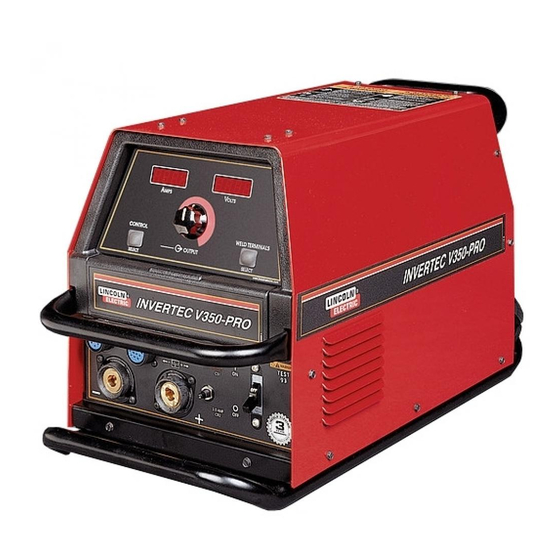
INVERTEC V350-PRO (CE)
Safety Depends on You
Lincoln arc welding and cutting
equipment is designed and built
with safety in mind. However, your
overall safety can be increased by
proper installation ... and thought-
ful operation on your part. DO
NOT INSTALL, OPERATE OR
REPAIR THIS EQUIPMENT
WITHOUT
READING
MANUAL AND THE SAFETY
PRECAUTIONS CONTAINED
THROUGHOUT. And, most
importantly, think before you act
and be careful.
Date of Purchase:
Serial Number:
Code Number:
Model:
Where Purchased:
ISO 9001
ANSI RAB
QMS
Designed and Manufactured Under a
Quality Program Certified by
ABS Quality Evaluations, Inc.
to ISO 9001 Requirements.
CERTIFICATE NUMBER: 30273
• Sales and Service through Subsidiaries and Distributors Worldwide •
Cleveland, Ohio 44117-1199 U.S.A. TEL: 216.481.8100 FAX: 216.486.1751 WEB SITE: www.lincolnelectric.com
™
For use with machines Code; 10670
THIS
IEC 974-1
IP21S
OPERATOR'S MANUAL
• World's Leader in Welding and Cutting Products •
L I N
C O
E L
L N
E C
T R
I C
I N
W A
V E
R N
IN
G
R T
E C
R E
M O
T E
V 3
5 0
- P
R O
P O
W
E R
O N
O F
F
Copyright © 2001 Lincoln Global Inc.
IM708
January, 2001
Advertisement
Table of Contents
Troubleshooting

Related Manuals for Lincoln INVERTEC V350-PRO


Summary of Contents for Lincoln INVERTEC V350-PRO
- Page 1 ABS Quality Evaluations, Inc. to ISO 9001 Requirements. CERTIFICATE NUMBER: 30273 Copyright © 2001 Lincoln Global Inc. • World's Leader in Welding and Cutting Products • • Sales and Service through Subsidiaries and Distributors Worldwide • Cleveland, Ohio 44117-1199 U.S.A. TEL: 216.481.8100 FAX: 216.486.1751 WEB SITE: www.lincolnelectric.com...
-
Page 2: California Proposition 65 Warnings
351040, Miami, Florida 33135 or CSA Standard W117.2-1974. A Free copy of “Arc Welding Safety” booklet E205 is available from the Lincoln Electric Company, 22801 St. Clair Avenue, Cleveland, Ohio 44117-1199. BE SURE THAT ALL INSTALLATION, OPERATION, MAINTENANCE AND REPAIR PROCEDURES ARE PERFORMED ONLY BY QUALIFIED INDIVIDUALS. -
Page 3: Electric Shock Can Kill
SAFETY ARC RAYS can burn. ELECTRIC SHOCK can 4.a. Use a shield with the proper filter and cover kill. plates to protect your eyes from sparks and 3.a. The electrode and work (or ground) circuits the rays of the arc when welding or observing are electrically “hot”... - Page 4 SAFETY WELDING SPARKS can CYLINDER may explode cause fire or explosion. if damaged. 6.a. Remove fire hazards from the welding area. 7.a. Use only compressed gas cylinders If this is not possible, cover them to prevent containing the correct shielding gas for the the welding sparks from starting a fire.
- Page 5 SAFETY zones où l’on pique le laitier. PRÉCAUTIONS DE SÛRETÉ 6. Eloigner les matériaux inflammables ou les recouvrir afin de Pour votre propre protection lire et observer toutes les instructions prévenir tout risque d’incendie dû aux étincelles. et les précautions de sûreté specifiques qui parraissent dans ce manuel aussi bien que les précautions de sûreté...
- Page 6 (89/336/EEC). It was manufactured in conformity with a national standard that implements a harmonized standard: EN 50 199 Electromagnetic Compatibility (EMC) Product Standard for Arc Welding Equipment. It is for use with other Lincoln Electric equipment. It is designed for industrial and professional use. Introduction All electrical equipment generates small amounts of electromagnetic emission.
- Page 7 SAFETY ELECTROMAGNETIC COMPATIBILITY (EMC) The size of the surrounding area to be considered will depend on the structure of the building and other that are taking place. The surrounding area may extend beyond the boundaries of the premises. Methods of Reducing Emissions Mains Supply Welding equipment should be connected to the mains supply according to the manufacturer s recomme If interference occurs, it may be necessary to take additional precautions such as filtering of the mains s...
- Page 8 QUALITY product by Lincoln Electric. We want you Thank You to take pride in operating this Lincoln Electric Company product ••• as much pride as we have in bringing this product to you! Please Examine Carton and Equipment For Damage Immediately When this equipment is shipped, title passes to the purchaser upon receipt by the carrier.
-
Page 9: Table Of Contents
viii viii TABLE OF CONTENTS Page Installation .......................Section A Technical Specifications ..................A-1 Safety Precautions ..................A-2 Select Suitable Location..................A-2 Stacking ......................A-2 Tilting.......................A-2 Input and Grounding Connections ..............A-2 Power Cord Connection ..................A-2 Connection of Wire Feeders to V350-PRO (CE)..........A-2 Remote Control of Invertec ................A-3 Undercarriage Mountings................A-3 Parallel Operations..................A-4 Ouick Disconnect Plugs ..................A-4... -
Page 10: Installation
INSTALLATION TECHNICAL SPECIFICATIONS - INVERTEC V350-PRO (CE) INPUT AC VOLTAGE & DC OUTPUT Product Ordering Input AC Rated DC Output Output Weight Dimensions Name Information Voltage Amps/Volts/Duty Cycle Range with Cord HxWxD 50/60 Hz (continuous) 350A / 34V / 60% 14.7”x12.5”x... -
Page 11: Safety Precautions
SELECT SUITABLE LOCATION CONNECTIONS OF WIRE FEEDERS TO V350-PRO (CE) LN-25 Connection Instructions The Invertec V350-PRO (CE) will operate in harsh environments. Even so, it is important that simple pre- • Turn the Invertec power switch "off". ventative measures are followed in order to assure •... -
Page 12: Connection Of Wire Feeders To V350-Pro (Ce
INSTALLATION TIG MODULE K930-2 LN-10 Connection Instructions The TIG Module connects to the “CE” version with a • Turn the Invertec power switch "off". K936-1 (9-14 pin) control cable. Connect the K936-1 • Connect the K1505 control cable from the LN-10 to to the 115VAC Wire Feeder Amphenol on the rear of the Invertec 24/42VAC 14-pin amphenol connector the V350-PRO (CE). -
Page 13: Parallel Operations
INSTALLATION PARALLEL OPERATION The V350-PRO (CE) are operable in parallel in CC mode. For best results, the currents of each machine should be reasonably well shared. As an example, with two machines set up in parallel for a 400 amp procedure, each machine should be set to deliver approximately 200 amps, not 300 amps from one and 100 amps from the other. -
Page 14: Operation
• Adjustment is indicated by the meters as stated PRODUCT DESCRIPTION & DUTY CYCLE above. The Invertec V350-PRO (CE) offers multi mode CV • When in TIG modes, this control sets the maximum and CC DC welding and is rated at 350 amps, 34 volts welding current. - Page 15 OPERATION 5. THERMAL 7. WELD MODE SELECT • This status light indicates when the power source The Mode Control button selects the following welding has been driven into thermal overload. If the output modes desired. terminals were "ON", the "ON" light will blink indicat- ing that the output will be turned back on once the CC-STICK SOFT: The Stick Soft process features unit cools down to an acceptable temperature level.
-
Page 16: Remote Control Of The Output Control And Weld Terminals
• The Arc Control is not used in the TIG mode. remote output controls.If after connecting or removing a remote, the Invertec V350-PRO (CE) did not config- CV-WIRE: The CV-WIRE mode features continuous ured the way you would like the local or remote con- control from 10 to 45 volts. -
Page 17: Design Features And Advantages
• F.A.N. (fan as needed). Cooling fan runs only when V350-PRO (CE)’s front panel Output Control.) necessary • Remotes of this type offered by Lincoln Electric are • Thermostatically protected. the K857, K812 and K870. • Designed to the IEC 974-1 Standard. -
Page 18: Auxiliary Power
• The V350-PRO (CE) can only be used with the rec- ommended equipment and options. RECOMMENDED PROCESSES Properly equipped, the Invertec V350-PRO (CE) supports GMAW, FCAW, SMAW, GTAW and CAC- A processes for a variety of materials, including mild steel, stainless steel, cored wires, and alu-... -
Page 19: Accessories
ACCESSORIES OPTIONS / ACCESSORIES "CE" VERSION – K1728-3 • The "CE" version is the Factory version with the addition of power line filtering allowing the machine to comply with the European and Australian EMC emission requirements. • In this form, the V350-PRO (CE) provides the hard- ware to power and connect to 24, 42 or 115 VAC wire feeders. -
Page 20: Maintenance
MAINTENANCE VISUAL INSPECTION SAFETY PRECAUTIONS WARNING Clean interior of machine with a low pressure air stream. Make a thorough inspection of all compo- ---------------------------------------------------------------------- nents. Look for signs of overheating, broken leads or other obvious problems. Many problems can be ELECTRIC SHOCK can kill. -
Page 21: How To Use Troubleshooting Guide
HOW TO USE TROUBLESHOOTING GUIDE WARNING Service and Repair should only be performed by Lincoln Electric Factory Trained Personnel. Unauthorized repairs performed on this equipment may result in danger to the technician and machine operator and will invalidate your factory warranty. For your safety and to avoid Electrical Shock, please observe all safety notes and precautions detailed throughout this manual. -
Page 22: Troubleshooting
CAUTION If for any reason you do not understand the test procedures or are unable to perform the tests/repairs safely, contact your Local Lincoln Authorized Field Service Facility for technical troubleshooting assistance before you proceed. V350-PRO (CE) - Page 23 Authorized Field Service Facility. CAUTION If for any reason you do not understand the test procedures or are unable to perform the tests/repairs safely, contact your Local Lincoln Authorized Field Service Facility for technical troubleshooting assistance before you proceed. V350-PRO (CE)
-
Page 24: Fault Codes
Shop mode CAUTION If for any reason you do not understand the test procedures or are unable to perform the tests/repairs safely, contact your Local Lincoln Authorized Field Service Facility for technical troubleshooting assistance before you proceed. V350-PRO (CE) -
Page 25: Displays
5 second period, the display will revert to the above mode. CAUTION If for any reason you do not understand the test procedures or are unable to perform the tests/repairs safely, contact your Local Lincoln Authorized Field Service Facility for technical troubleshooting assistance before you proceed. V350-PRO (CE) - Page 26 DIAGRAMS V350-PRO (CE)
- Page 27 DIAGRAMS V350-PRO (CE)
- Page 28 DIAGRAMS V350-PRO (CE)
- Page 29 DIAGRAMS V350-PRO (CE)
- Page 30 DIAGRAMS V350-PRO (CE)
- Page 31 DIAGRAMS V350-PRO (CE)
- Page 32 DIAGRAMS ENHANCED DIAGRAM xxxxxxx V350-PRO (CE)
- Page 33 DIAGRAMS V350-PRO (CE)
- Page 34 NOTES...
- Page 35 Year AMERICAN EXPRESS USE THIS FORM TO ORDER: Order from: BOOK DIVISION, The Lincoln Electric Company, 22801 St. Clair Avenue, Cleveland, Ohio 44117-1199 for fastest service, FAX this completed form to: 216-361-5901 BOOKS OR FREE INFORMATIVE CATALOGS Telephone: 216-383-2211 or,...
- Page 36 ● ● ● Do not touch electrically live parts or Keep flammable materials away. Wear eye, ear and body protection. WARNING electrode with skin or wet clothing. ● Insulate yourself from work and ground. Spanish ● ● ● No toque las partes o los electrodos Mantenga el material combustible Protéjase los ojos, los oídos y el AVISO DE...
- Page 37 ● ● ● Keep your head out of fumes. Turn power off before servicing. Do not operate with panel open or WARNING ● Use ventilation or exhaust to guards off. remove fumes from breathing zone. Spanish ● Los humos fuera de la zona de res- ●...
- Page 38 • World's Leader in Welding and Cutting Products • • Sales and Service through Subsidiaries and Distributors Worldwide • Cleveland, Ohio 44117-1199 U.S.A. TEL: 216.481.8100 FAX: 216.486.1751 WEB SITE: www.lincolnelectric.com...
Need help?
Do you have a question about the INVERTEC V350-PRO and is the answer not in the manual?
Questions and answers