Table of Contents
Advertisement
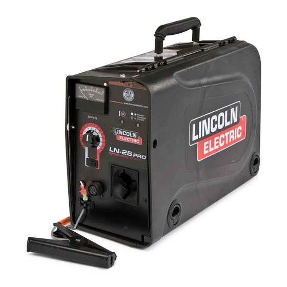
Operator's Manual
™
LN-25
Register your machine:
www.lincolnelectric.com/register
Authorized Service and Distributor Locator:
www.lincolnelectric.com/locator
Save for future reference
Date Purchased
Code: (ex: 10859)
Serial: (ex: U1060512345)
IM10076
| Issue Date Jun-16
© Lincoln Global, Inc. All Rights Reserved.
PRO
For use with machines having Code Numbers:
11746, 11747
Need Help? Call 1.888.935.3877
to talk to a Service Representative
Hours of Operation:
8:00 AM to 6:00 PM (ET) Mon. thru Fri.
After hours?
Use "Ask the Experts" at lincolnelectric.com
A Lincoln Service Representative will contact you
no later than the following business day.
For Service outside the USA:
Email: globalservice@lincolnelectric.com
Advertisement
Table of Contents

Related Manuals for Lincoln LN-25 PRO


Summary of Contents for Lincoln LN-25 PRO
- Page 1 8:00 AM to 6:00 PM (ET) Mon. thru Fri. Save for future reference After hours? Use “Ask the Experts” at lincolnelectric.com A Lincoln Service Representative will contact you Date Purchased no later than the following business day. For Service outside the USA: Email: globalservice@lincolnelectric.com...
- Page 2 (See below). SAFETY DEPENDS ON YOU USE NATURAL DRAFTS or fans to keep the fumes away Lincoln arc welding and cutting equipment is designed and built from your face. with safety in mind. However, your overall safety can be increased If you de velop unusual symptoms, see your supervisor.
- Page 3 MAGNETIC FIELDS MAY W117.2-1974. A Free copy of “Arc Welding Safety” booklet BE DANGEROUS E205 is available from the Lincoln Electric Company, 22801 St. Clair Avenue, Cleveland, Ohio 44117-1199. 2.a. Electric current flowing through any conductor BE SURE THAT ALL INSTALLATION, OPERATION, causes localized Electric and Magnetic Fields (EMF).
-
Page 4: Electric Shock Can Kill
S FETY ELECTRIC SHOCK ARC RAYS CAN BURN. CAN KILL. 3.a. The electrode and work (or ground) circuits are 4.a. Use a shield with the proper filter and cover plates to protect your electrically “hot” when the welder is on. Do eyes from sparks and the rays of the arc when welding or not touch these “hot”... - Page 5 S FETY WELDING AND CUTTING CYLINDER MAY EXPLODE IF SPARKS CAN CAUSE DAMAGED. FIRE OR EXPLOSION. 7.a. Use only compressed gas cylinders containing the correct shielding gas for the process used 6.a. Remove fire hazards from the welding area. If and properly operating regulators designed for this is not possible, cover them to prevent the welding sparks the gas and pressure used.
- Page 6 SAFETY PRÉCAuTIONS DE SÛRETÉ 6. Eloigner les matériaux inflammables ou les recouvrir afin de prévenir tout risque d’incendie dû aux étincelles. Pour votre propre protection lire et observer toutes les instructions et les précautions de sûreté specifiques qui parraissent dans ce 7.
- Page 7 2004/108/EC. It was manufactured in conformity with a national standard that implements a harmonized standard: EN 60974-10 Electromagnetic Compatibility (EMC) Product Standard for Arc Welding Equipment. It is for use with other Lincoln Electric equipment. It is designed for industrial and professional use. Introduction All electrical equipment generates small amounts of electromagnetic emission.
- Page 8 SAFETY Electromagnetic Compatibility (EMC) The size of the surrounding area to be considered will depend on the structure of the building and other activities that are taking place. The surrounding area may extend beyond the boundaries of the premises. Methods of Reducing Emissions Mains Supply Welding equipment should be connected to the mains supply according to the manufacturer’s recommenda- tions.
-
Page 9: Table Of Contents
viii viii TAbLE OF CONTENTS Page –––––––––––––––––––––––––––––––––––––––––––––––––––––––––––––––––––––––––––––––– Installation........................Section A Technical Specifications .......................A-1 Safety Precautions .......................A-2 Location ..........................A-2 High Frequency Protection ....................A-2 Weld cable Sizes, Electrode Lead..................A-2 Shielding Gas Connection ....................A-3 Wire Drive Configuration ......................A-4 Gun Receiver Bushing, Thumb Screw, Socket Head Cap Screw ........A-4 Procedure to Install Drive Rolls and Wire Guides ..............A-5 Loading Spools of Wire ......................A-5 Pressure Arm Adjustment ....................B-6... -
Page 10: Installation
INSTALLATION TEChNICAL SPECIFICATIONS – LN-25™ PRO (K2613-5, K2613-7) INPuT VOLTAGE and CuRRENT INPuT VOLTAGE ± 10% INPuT AMPERES 15-110 VDC RATED OuTPuT @ 104°F (40°C) DuTY CYCLE INPuT AMPERES 60% rating GEARING - WIRE FEED SPEED RANGE-WIRE SIzE GMAW FCAW GEARING WFS RANGE WIRE SIzES... -
Page 11: Safety Precautions
INSTALLATION SAFETY PRECAuTIONS The LN-25™ Pro is rated IP23 and is suitable for outdoor use. WARNING The handle of the LN-25™ Pro is intended for moving the wire feeder about the work place only. ELECTRIC ShOCK CAN KILL. When suspending a wire feeder, insulate the •... -
Page 12: Shielding Gas Connection
INSTALLATION ShIELDING GAS CONNECTION 6. Before opening the cylinder valve, turn the regulator adjusting knob counterclockwise until the adjusting WARNING spring pressure is released. 7. Standing to one side, open the cylinder valve slowly a CYLINDER may explode if fraction of a turn. When the cylinder pressure gage damaged. -
Page 13: Wire Drive Configuration
INSTALLATION WIRE DRIVE CONFIGuRATION 9. Rotate the gun bushing until the thumb screw hole aligns with the thumb screw hole in the feed plate. (See Figure A.2) Slide the gun receiver bushing into the wire drive GuN buShING, ThuMb SCREW AND and verify the thumb screw holes are aligned. -
Page 14: Procedure To Install Drive Rolls And Wire Guides
INSTALLATION PROCEDuRE TO INSTALL DRIVE ROLLS 7. Install a drive roll on each hub assembly secure with the triangular lock. AND WIRE GuIDES 8. Install the outer wire guide by aligning it with the pins and tightening the knurled thumbscrews. WARNING 9. -
Page 15: Pressure Arm Adjustment
INSTALLATION GuN CONNECTION PRESSuRE ARM and ADJuSTMENT WARNING WARNING ELECTRIC ShOCK can kill. ELECTRIC ShOCK can kill. • Turn the input power OFF at the weld- • Turn the input power OFF at the ing power source before installation or welding power source before instal- changing drive rolls and/or guides. - Page 16 INSTALLATION POWER SOuRCE TO LN-25™ PRO CAbLE CONNECTION DIAGRAMS ACROSS ThE ARC SET-uPS CC Power Sources with Output Terminals Always hot (See Figure A.5) FIGuRE A.5 Description If the power source has a Remote/Local switch, place the switch in the Local position. K2613-5 LN-25™...
- Page 17 INSTALLATION CV Power Sources with Stud Connectors and no Remote/Local Switch. (See Figure A.7) FIGuRE A.7 Ranger 250, 250 LPG Ranger 305G, 305D LN-25™ Pro Ranger 10,000 Electrode Ranger 3 Phase (Across the Arc) Ranger 225, 225GXT Commander 300 Work clip Vantage 300, 400, 500 Air Vantage 500 Work...
- Page 18 INSTALLATION CV Power Source with Twist-Mate Connectors and no Remote/Local Switch. (See Figure A.9) FIGuRE A.9 Jumper CV-250 CV-300 LN-25™ PRO Electrode (Across the Arc) Work clip Work Description Place CV/CC switch in the feeder in the "CV" position. K2613-5 LN-25™...
-
Page 19: Operation
OPERATION SAFETY PRECAuTIONS GRAPhIC SYMbOLS ThAT APPEAR ON ThIS MAChINE OR IN ThIS MANuAL READ AND uNDERSTAND ENTIRE SECTION bEFORE OPERATING MAChINE. INPuT POWER WARNING • ELECTRIC ShOCK CAN KILL. unless using COLD FEED fea- ture, when feeding with gun trig- ger, the electrode and drive mechanism are always electri- cally energized and could... -
Page 20: Definition Of Welding Terms
OPERATION General Functional Description DEFINITION OF WELDING TERMS All LN-25™ PRO’s have adjustable WFS range for improving the knob sensitivity. The low range is great for critical welds with Innershield wires, and the upper • Wire Feed Speed range is suitable for general purpose welding. Selection of the WFS range is by a rocker switch or through the set-up menu on meters with digital dis- •... -
Page 21: Case Front Controls
OPERATION (See Customer Assistance Policy in the front of this Instruction Manual) CASE FRONT CONTROLS (See Figure b.1) FIGuRE b.1 ITEM DESCRIPTION Analog Voltmeter Wire Feed Speed Knob Wire Feed Speed Range Switch 5-pin gun trigger connector Work sense lead Thermal LED, Motor Overload Polarity LED 1. - Page 22 Many variables power sources, the wire feed speed changes as the beyond the control of The Lincoln Electric Company arc voltage changes. When the arc voltage increases, affect the results obtained in using the LN-25™ PRO the wire feed speed will increase;...
-
Page 23: Constant Current Wire Welding
For constant current operation, the power source is For these reasons, Lincoln Electric does NOT recom- set to deliver the specified current. The power source mend constant current semiautomatic welding for... - Page 24 Always use quality electrode, such as L-50 or L-56 WFS range for standard torque: from Lincoln Electric. High = 50 to 700 ipm Low = 50 to 200 ipm 7. POLARITY LED...
-
Page 25: Internal Controls
OPERATION INTERNAL CONTROLS FIGuRE b.2 ITEM DESCRIPTION 2 Step Trigger Interlock Switch CV / CC Switch Pressure Adjustment Arm Optional Timer Kit Spool Retainer Spindle Brake Gun Bushing, Thumb Screw and Socket Head Cap Screw Drive Hubs Cold Feed Pushbutton LN-25™... -
Page 26: Internal Controls Decription
OPERATION INTERNAL CONTROLS DESCRIPTION 2. CV/CC SWITCh (See Figure B.2) The CV/CC switch sets the wire feed speed control method for the 1. 2 STEP - TRIGGER wire feeder. INTERLOCK SWITCh In the CV position, the wire feed speed remains constant during The 2 Step - Trigger Interlock welding. -
Page 27: Rear Controls
OPERATION FIGuRE b.4 REAR CONTROLS: (See Figure B.4) 1. GAS PuRGE PuShbuTTON The gas solenoid valve will energize but neither the power source output nor the drive motor will be turned on. The Gas Purge switch is useful for setting the proper flow rate of shielding gas. -
Page 28: Accessories
ACCESSORIES FACTORY INSTALLED EQuIPMENT • K1500-2 Gun Receiver Bushing. DRIVE ROLL KITS, 2 ROLL DRIVE WIRE TYPE ELECTRODE SIzE KP KIT Steel Wires: .023-.030 (0.6-0.8mm) KP1696-030S .035 (0.9mm) KP1696-035S Includes: 2 V groove KP1696-045S .045 (1.2mm) drive rolls and inner .052 (1.4mm) KP1696-052S 1/16 (1.6mm) - Page 29 ACCESSORIES K2330-2 Timer Kit Includes: Panel and harness for adjusting preflow, burnback and postflow times. K2596-2 Plastic Case Includes: a complete engi- neered plastic case. K1796-xx AWG 1/0 Co-Axial Power Cable Includes: 1/0 Coaxial weld cable of length "xx". Ends of the weld cable have lug con- nections.
- Page 30 Ground Clamp. K910-2 Ground Clamp Includes: One 500 Amp Ground Clamp. Gun Receiver Bushing (for guns Includes: Gun receiver bush- K1500-1 with K466-1 Lincoln gun connec- ing, set screw and hex key tors; Innershield and Subarc guns) wrench. LN-25™ PRO...
- Page 31 ACCESSORIES Gun Receiver Bushing (for guns with K466-2, K466-10 Lincoln gun Includes: Gun receiver bush- K1500-2 connectors; Magnum 200/300/400 ing with hose nipple, set screw guns and compatible with Tweco® and hex key wrench. #2-#4) Gun Receiver Bushing (for guns...
-
Page 32: Maintenance
MAINTENANCE SAFETY PRECAuTIONS FIGuRE D.1 WARNING ELECTRIC ShOCK can kill. • Turn the input power OFF at the Calibration welding power source before Screw installation or changing drive rolls and/or guides. • Do not touch electrically live parts. • When inching with the gun trigger, electrode and drive mechanism are "hot"... - Page 33 MAINTENANCE FIGuRE D.2 WIRE FEED SPEED VALIDATION Calibration of the LN-25™ PRO may be required when the P.C. board, wire feed speed potentiometer or motor is replaced or serviced. Calibration matches the scale on the name plate to the actual wire feed speed. To calibrate the LN-25™...
-
Page 34: Troubleshooting
TO uSE TROubLEShOOTING GuIDE WARNING Service and Repair should only be performed by Lincoln Electric Factory Trained Personnel. Unauthorized repairs performed on this equipment may result in danger to the technician and machine operator and will invalidate your factory warranty. For your safety and to avoid Electrical Shock, please observe all safety notes and precautions detailed throughout this manual. - Page 35 6. Replace solenoid. CAuTION If for any reason you do not understand the test procedures or are unable to perform the tests/repairs safely, contact your Local Lincoln Authorized Field Service Facility for technical troubleshooting assistance before you proceed. LN-25™ PRO...
- Page 36 CAuTION If for any reason you do not understand the test procedures or are unable to perform the tests/repairs safely, contact your Local Lincoln Authorized Field Service Facility for technical troubleshooting assistance before you proceed. LN-25™ PRO...
- Page 37 CAuTION If for any reason you do not understand the test procedures or are unable to perform the tests/repairs safely, contact your Local Lincoln Authorized Field Service Facility for technical troubleshooting assistance before you proceed. LN-25™ PRO...
- Page 38 Enhanced Diagram DIAGRAMS LN-25™ PRO...
- Page 39 DIMENSION PRINT LN-25™ PRO...
- Page 40 NOTES LN-25™ PRO...
- Page 41 Do not touch electrically live parts or Keep flammable materials away. Wear eye, ear and body protection. WARNING electrode with skin or wet clothing. Insulate yourself from work and ground. Spanish No toque las partes o los electrodos Mantenga el material combustible Protéjase los ojos, los oídos y el AVISO DE bajo carga con la piel o ropa moja-...
- Page 42 Keep your head out of fumes. Turn power off before servicing. Do not operate with panel open or WARNING Use ventilation or exhaust to guards off. remove fumes from breathing zone. Spanish Los humos fuera de la zona de res- Desconectar el cable de ali- No operar con panel abierto o AVISO DE...
- Page 43 Lincoln Electric for advice or information about their use of our products. We respond to our customers based on the best information in our possession at that time. Lincoln Electric is not in a position to warrant or guarantee such advice, and assumes no liability, with respect to such information or advice.
Need help?
Do you have a question about the LN-25 PRO and is the answer not in the manual?
Questions and answers