Table of Contents
Advertisement
Operator's Manual
FLEXTEC
Register your machine:
www.lincolnelectric.com/register
Authorized Service and Distributor Locator:
www.lincolnelectric.com/locator
Save for future reference
Date Purchased
Code: (ex: 10859)
Serial: (ex: U1060512345)
IM10062-C
| Issue D ate Oct-13
© Lincoln Global, Inc. All Rights Reserved.
™
450
For use with machines having Code Numbers:
11626, 11754, 11941, 12038
Advertisement
Table of Contents
Troubleshooting

Related Manuals for Lincoln FLEXTEC 450


Summary of Contents for Lincoln FLEXTEC 450
- Page 1 For use with machines having Code Numbers: 11626, 11754, 11941, 12038 Register your machine: www.lincolnelectric.com/register Authorized Service and Distributor Locator: www.lincolnelectric.com/locator Save for future reference Date Purchased Code: (ex: 10859) Serial: (ex: U1060512345) IM10062-C | Issue D ate Oct-13 © Lincoln Global, Inc. All Rights Reserved.
- Page 2 USE NATURAL DRAFTS or fans to keep the fumes away from your face. Lincoln arc welding and cutting equipment is designed and built with safety in mind. However, your overall safety can be increased by If you de velop unusual symptoms, see your supervisor. Perhaps the proper installation ...
-
Page 3: California Proposition 65 Warnings
American Welding Society, P.O. Box 351040, Miami, Florida 33135 or ELECTRIC AND CSA Standard W117.2-1974. A Free copy of “Arc Welding Safety” MAGNETIC FIELDS MAY booklet E205 is available from the Lincoln Electric Company, 22801 St. Clair Avenue, Cleveland, Ohio 44117-1199. BE DANGEROUS BE SURE THAT ALL INSTALLATION, OPERATION, 2.a. -
Page 4: Electric Shock Can Kill
SAFETY ELECTRIC SHOCK ARC RAYS CAN BURN. CAN KILL. 3.a. The electrode and work (or ground) circuits are 4.a. Use a shield with the proper filter and cover plates to protect your electrically “hot” when the welder is on. Do eyes from sparks and the rays of the arc when welding or not touch these “hot”... - Page 5 SAFETY WELDING AND CUTTING CYLINDER MAY EXPLODE IF SPARKS CAN CAUSE DAMAGED. FIRE OR EXPLOSION. 7.a. Use only compressed gas cylinders containing the correct shielding gas for the process used 6.a. Remove fire hazards from the welding area. If and properly operating regulators designed for this is not possible, cover them to prevent the the gas and pressure used.
-
Page 6: Table Of Contents
Input Fuse and Supply Wire Considerations...........A-5 Input Voltage Selection ...................A-5 Cable Connections..................A-6 Recommended Electrode and Work Cable for arc Welding ........A-7 Output Cable Guidelines..................A-7 Connection Diagrams Flextec 450 to Wire Feeders ......A-8 thru A-11 ________________________________________________________________________ Operation ......................Section B Safety Precautions ....................B-1 Graphic Symbols....................B-1, B-2 Product Description ....................B-2... -
Page 7: Technical Specifications
INSTALLATION TECHNICAL SPECIFICATIONS - FLEXTEC™ 450 POWER SOURCE-INPUT VOLTAGE AND CURRENT Input Amperes Input Voltage ± 10% Model Duty Cycle Power Factor @ Idle Power Rated Output 60% rating 72 Watts 37 / 27 / 22 K2882-2 Max. 380 / 460 / 575 / 3 / 50 / 60 100% rating 29 / 21 / 17 (fan on) -
Page 8: Physical Dimensions
INSTALLATION WELDING PROCESS OUTPUT RANGE (AMPERES) OCV (U PROCESS 40-500 GMAW (CV) GTAW (CC) 10-500 SMAW (CC) 15-500 40-500 FCAW-GS (CV) FCAW-SS (CV) 40-500 PHYSICAL DIMENSIONS MODEL HEIGHT WIDTH DEPTH WEIGHT 26.66in (677mm) 125lbs (56.6kg)* K2882-2 18.80in (478mm) 14.14in (359mm) TEMPERATURE RANGES STORAGE TEMPERATURE RANGE OPERATING TEMPERATURE RANGE... -
Page 9: Safety Precautions
INSTALLATION SAFETY PRECAUTIONS STACKING WARNING The Flextec™ 450 cannot be stacked. ELECTRIC SHOCK can kill. ENVIRONMENTAL LIMITATIONS ONLY QUALIFIED PERSONNEL SHOULD PERFORM THIS INSTALLATION. The Flextec™ 450 is IP23 rated for use in an outdoor • TURN OFF INPUT POWER TO THE environment. -
Page 10: Input Connection
INSTALLATION INPUT VOLTAGE SELECTION WARNING For codes 11941 and below ELECTRIC SHOCK can kill. Welders are shipped connected for 460 Volt input ONLY A QUALIFIED ELECTRICIAN voltage. To move this connection to a different input SHOULD CONNECT THE INPUT voltage, see the diagram located on the inside panel LEADS TO THE FLEXTEC™... - Page 11 INSTALLATION INPUT VOLTAGE SELECTION INPUT CONNECTION For codes 12038 and above (See Figure A.1a) For codes 12038 and above Welders are shipped connected for 460 Volt input voltage. To move this connection to a different input Use a three-phase supply line. A 1.40 inch (36 mm) voltage, reconnect the auxiliary lead (indicated as ʼAʼ) diameter access hole for the input supply is located on located at the back of the machine to the appropriate...
-
Page 12: Cable Connections
INSTALLATION CABLE CONNECTIONS See FIGURE A.2 for locating 6-pin and 14-pin con- nectors on the front of the FLEXTEC™ 450. 6-PIN REMOTE CONTROL CONNECTOR Function Wiring 6-pin remote 77 Remote potentiometer, 5K control con- 76 Remote potentiometer, wiper nector for 75 Remote potentiometer, common remote or Trigger, common... -
Page 13: Output Cable Guidelines
(+) output stud on the power General Guidelines source. Connect a work lead from the negative (-) Genuine Lincoln control cables should be used at all power source output stud to the work piece. times (except where noted otherwise). Lincoln cables are specifically designed for the communication and •... - Page 14 INSTALLATION CONNECTING LF-72 AND LF-74 TO THE FLEXTEC ™ WIRE FEEDER 14-PIN CONTROL CABLE K1797-XX LF-72 FLEXTEC™-450 ELECTRODE LF-74 WORK CONTROL SETTING WELD MODE CV, CV-INNERSHIELD WELD TERMINALS LOCAL REMOTE/LOCAL (REMOTE IF K2329-1 INSTALLED) VOLTMETER POLARITY PROCESS DEPENDENT FLEXTEC™ 450...
- Page 15 INSTALLATION CONNECTING LN-10 AND DH-10 TO THE FLEXTEC ™ WIRE FEEDER 14-PIN CONTROL CABLE K1501-XX LN-10 FLEXTEC™-450 DH-10 ELECTRODE WORK CONTROL SETTING WELD MODE CV, CV-INNERSHIELD WELD TERMINALS REMOTE/LOCAL REMOTE VOLTMETER POLARITY PROCESS DEPENDENT LN-10,DH-10 CONTROL SWITCH Setting the DIP Switches SETUP The DIP switches are each labeled with an “ON”...
- Page 16 A-10 A-10 INSTALLATION CONNECTING LN-15(K1870-1) TO THE FLEXTEC ™ WIRE FEEDER LN-15 FLEXTEC™-450 ELECTRODE (K1870-1) WORK CLIP WORK CONTROL SETTING WELD MODE CV, CV-INNERSHIELD WELD TERMINALS REMOTE/LOCAL LOCAL VOLTMETER POLARITY PROCESS DEPENDENT CONNECTING LN-15(K1871-1) TO THE FLEXTEC ™ WIRE FEEDER 14-PIN CONTROL CABLE K1819-XX LN-15 FLEXTEC™-450...
- Page 17 A-11 A-11 INSTALLATION CONNECTING LN-25 PRO AND LN-25 PIPE TO THE FLEXTEC ™ WIRE FEEDER LN-25 PRO FLEXTEC™-450 LN-25 PIPE ELECTRODE WORK CLIP WORK CONTROL SETTING WELD MODE CV, CV-INNERSHIELD WELD TERMINALS REMOTE/LOCAL LOCAL VOLTMETER POLARITY PROCESS DEPENDENT CONNECTING LN-25 PRO DUAL POWER TO THE FLEXTEC ™...
- Page 18 OPERATION SAFETY PRECAUTIONS GRAPHIC SYMBOLS THAT APPEAR ON THIS MACHINE Read this entire section of operating instructions before operating the machine. OR IN THIS MANUAL WARNING INPUT POWER ELECTRIC SHOCK can kill. • Unless using cold feed feature, when feeding with gun trigger, the electrode and drive mechanism are always electrically energized and could remain energized several...
-
Page 19: Product Description
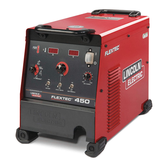
OPERATION GRAPHIC SYMBOLS THAT PRODUCT DESCRIPTION APPEAR ON THIS MACHINE The Flextec™ 450 is a multi-process CC/CV DC OR IN THIS MANUAL inverter and is rated for 450 amps, 38 volts at a 60% duty cycle. The Flextec is intended for both factory and field operation. -
Page 20: Recommended Processes And Equipment
OPERATION RECOMMENDED PROCESSES AND EQUIPMENT RECOMMENDED PROCESSES The Flextec™ 450 is designed for CC-SMAW, CC-GTAW (lift tig), CV-GMAW, CV-FCAW-SS and CV-FCAW-GS welding processes. CAG (arc gouging) is also supported. PROCESS LIMITATIONS The Flextec™ 450 is suitable only for the processes listed. EQUIPMENT LIMITATIONS Operating Temperature Range is -10°... -
Page 21: Case Front Controls
OPERATION CASE FRONT CONTROL DESCRIPTIONS (See Figure B.1) 11. Wire feeder voltmeter polarity selection toggle switch 1. Power Switch 12. Circuit breaker reset button for the 14-pin wire 2. Voltage Display Meter feeder connector 3. Amperage Display Meter 13. 14-pin wire feeder circular connector 4. -
Page 22: Power-Up Sequence
Output control is conducted by a single turn poten- responsibility of the builder/user. Many variables tiometer. (Adjustment is indicated by the meters.) beyond the control of The Lincoln Electric When in Remote Mode, this control sets the maximum Company affect the results obtained in applying welding current of the remote device. - Page 23 OPERATION INTERNAL CONTROLS - ENABLING VRD To Enter VRD™ Mode (VRD™ Enabled) ™ (For Code 11941 only) a. For 380V input: Switch #5 in the “ON” Internal Controls Description Position. The Control PC Board has one bank of Dip Switches. As shipped from the factory VRD™...
- Page 24 OPERATION VRD™ (VOLTAGE REDUCTION DEVICE) Amperage Display Meter • Prior to STICK or TIG operation (current flow), the INDICATOR LIGHT meter displays preset current value. (For Code 11941 only) • Prior to CV operation, the meter displays four dash- There are 2 indicator lights on the case front of the es indicating non-presettable AMPS.
- Page 25 OPERATION Output Control Dial BASIC MODES OF OPERATION • When the Local/Remote is set to Local, this dial sets the welding amperage. SMAW • When the Local/Remote is set to Remote, this dial This weld mode is a constant current (CC) mode fea- sets the maximum welding amperage.
- Page 26 OPERATION GTAW CV-GAS This weld mode is a constant current (CC) mode featuring con- This weld mode is a constant voltage (CV) mode featuring con- tinuous control from 10 – 500 amps. It is intended for the GTAW tinuous control from 10 to 45 volts. TIG welding processes.
- Page 27 B-10 B-10 OPERATION CV-INNERSHIELD This weld mode is a constant voltage (CV) mode fea- turing continuous control from 10 to 45 volts. It is intended for the FCAW-SS welding process and arc gouging. Hot Start – Toggle to “ON” position to provide more energy during the start of a weld.
-
Page 28: Options / Accessories
ACCESSORIES Hand Amptrol® - Provides 25 ft. OPTIONS / ACCESSORIES (7.6 m) of remote current control for TIG welding. (6-pin plug con- General Options nection). Order K963-3 K2149-1 Work Lead Package. Arc Start Switch - May be used in place of the Foot or Hand Amptrol®. - Page 29 MAINTENANCE SAFETY PRECAUTIONS PERIODIC MAINTENANCE WARNING Thermal Protection Thermostats protect the machine from excessive ELECTRIC SHOCK can kill. operating temperatures. Excessive temperatures may • Only Qualified personnel should be caused by a lack of cooling air or operating the perform this maintenance. machine beyond the duty cycle and output rating.
-
Page 30: How To Use Troubleshooting Guide
HOW TO USE TROUBLESHOOTING GUIDE WARNING Service and Repair should only be performed by Lincoln Electric Factory Trained Personnel. Unauthorized repairs performed on this equipment may result in danger to the technician and machine operator and will invalidate your factory warranty. For your safety and to avoid Electrical Shock, please observe all safety notes and precautions detailed throughout this manual. -
Page 31: Troubleshooting
CAUTION If for any reason you do not understand the test procedures or are unable to perform the tests/repairs safely, contact your Local Lincoln Authorized Field Service Facility for technical troubleshooting assistance before you proceed. FLEXTEC™ 450... -
Page 32: Using The Status Led To Troubleshoot System Problems
CAUTION If for any reason you do not understand the test procedures or are unable to perform the tests/repairs safely, contact your Local Lincoln Authorized Field Service Facility for technical troubleshooting assistance before you proceed. FLEXTEC™ 450... - Page 33 CAUTION If for any reason you do not understand the test procedures or are unable to perform the tests/repairs safely, contact your Local Lincoln Authorized Field Service Facility for technical troubleshooting assistance before you proceed. FLEXTEC™ 450...
- Page 34 Machine needs to be turned off and back on to reset. If any of these conditions persist contact an authorized Lincoln Field Service Shop. CAUTION If for any reason you do not understand the test procedures or are unable to perform the tests/repairs safely, contact your Local Lincoln Authorized Field Service Facility for technical troubleshooting assistance before you proceed.
- Page 35 DIAGRAMS ENHANCED DIAGRAM FLEXTEC™ 450...
- Page 36 DIAGRAMS FLEXTEC™ 450...
- Page 37 DIAGRAMS FLEXTEC™ 450...
- Page 38 DIAGRAMS FLEXTEC™ 450...
- Page 39 DIMENSION PRINT FLEXTEC™ 450...
- Page 40 NOTES FLEXTEC ™...
- Page 41 This parts list is provided as an informative guide only. It was accurate at the time of printing. These pages are only updated on the Service Navigator DVD and in Lincoln Electricʼs official Parts Book (BK-34). When ordering parts, always refer to Lincoln Electricʼs official Parts Book (BK-34) for the latest pages.
- Page 42 P-652-A P-652-A ILLUSTRATION OF SUB-ASSEMBLIES 08-15-2012 FLEXTEC ™...
- Page 43 P-652-A.1 P-652-A.1 Flextec ™ For Codes: 11626, 11754 & 11941 Do Not use this Parts List for a machine if its code number is not listed. Contact the Service Department for any code numbers not listed. Use the Illustration of Sub-Assemblies page and the table below to determine which sub assembly page and column the desired part is located on for your particular code machine.
- Page 44 P-652-C P-652-C Case Front Assembly & Door 11 11 08-15-2012 FLEXTEC ™...
- Page 45 P-652-C.1 P-652-C.1 # Indicates a change this printing. Use only the parts marked “x” in the column under the heading number called for in the model index page. 1 2 3 4 5 6 7 8 9 ITEM DESCRIPTION PART NO. QTY.
- Page 46 Note: When ordering new printed circuit boards indicate the dash number [ ] of the “Old” board that is to be replaced. This will aid Lincoln in supplying the correct and latest board along with any necessary jumpers or adapters. The dash number brackets [ ] have purposely been left blank so as to eliminate errors, confusion and updates.
- Page 47 NOTES FLEXTEC ™...
- Page 48 P-652-D P-652-D Divider Panel Assembly 11 11 08-15-2012 FLEXTEC ™...
- Page 49 Note: When ordering new printed circuit boards indicate the dash number [ ] of the “Old” board that is to be replaced. This will aid Lincoln in supplying the correct and latest board along with any necessary jumpers or adapters. The dash number brackets [ ] have purposely been left blank so as to eliminate errors, confusion and updates.
- Page 50 P-652-E P-652-E Base & Center Assembly 3D 3E 3E 3F 2B 2C 08-15-2012 FLEXTEC ™...
- Page 51 P-652-E.1 P-652-E.1 # Indicates a change this printing. Use only the parts marked “x” in the column under the heading number called for in the model index page. 1 2 3 4 5 6 7 8 9 ITEM DESCRIPTION PART NO. QTY.
- Page 52 P-652-F P-652-F Case Back Assembly 11 11 08-15-2012 FLEXTEC ™...
- Page 53 P-652-F.1 P-652-F.1 # Indicates a change this printing. Use only the parts marked “x” in the column under the heading number called for in the model index page. 1 2 3 4 5 6 7 8 9 ITEM DESCRIPTION PART NO. QTY.
- Page 54 P-652-G P-652-G Wraparound Assembly 08-15-2012 FLEXTEC ™...
- Page 55 • X • Wiring Diagram G6890-5 • • X Warranty Decal S22127-2 X X X Green Initiative Decal S28039-2 X X X Lincoln Logo Decal S27368-4 X X X Flextec Decal M22461 X X X Warning Decal M16196 X X X 08-15-2012 FLEXTEC ™...
- Page 56 NOTES FLEXTEC ™...
- Page 57 This parts list is provided as an informative guide only. It was accurate at the time of printing. These pages are only updated on the Service Navigator DVD and in Lincoln Electricʼs official Parts Book (BK-34). When ordering parts, always refer to Lincoln Electricʼs official Parts Book (BK-34) for the latest pages.
- Page 58 P-732-A P-732-A ILLUSTRATION OF SUB-ASSEMBLIES 02-04-2013 FLEXTEC ™...
- Page 59 P-732-A.1 P-732-A.1 Flextec ™ For Code: 12038 Do Not use this Parts List for a machine if its code number is not listed. Contact the Service Department for any code numbers not listed. Use the Illustration of Sub-Assemblies page and the table below to determine which sub assembly page and column the desired part is located on for your particular code machine.
- Page 60 P-732-C P-732-C Case Front Assembly & Door 02-04-2013 FLEXTEC ™...
- Page 61 Note: When ordering new printed circuit boards indicate the dash number [ ] of the “Old” board that is to be replaced. This will aid Lincoln in supplying the correct and latest board along with any necessary jumpers or adapters. The dash number brackets [ ] have purposely been left blank so as to eliminate errors, confusion and updates.
- Page 62 P-732-D P-732-D Divider Panel Assembly 11 11 02-04-2013 FLEXTEC ™...
- Page 63 Note: When ordering new printed circuit boards indicate the dash number [ ] of the “Old” board that is to be replaced. This will aid Lincoln in supplying the correct and latest board along with any necessary jumpers or adapters. The dash number brackets [ ] have purposely been left blank so as to eliminate errors, confusion and updates.
- Page 64 P-732-E P-732-E Base & Center Assembly 3E 3F 3D 3E 2B 2C 02-04-2013 FLEXTEC ™...
- Page 65 P-732-E.1 P-732-E.1 # Indicates a change this printing. Use only the parts marked “x” in the column under the heading number called for in the model index page. 1 2 3 4 5 6 7 8 9 ITEM DESCRIPTION PART NO. QTY.
- Page 66 P-732-F P-732-F Case Back Assembly 02-04-2013 FLEXTEC ™...
- Page 67 P-732-F.1 P-732-F.1 # Indicates a change this printing. Use only the parts marked “x” in the column under the heading number called for in the model index page. 1 2 3 4 5 6 7 8 9 ITEM DESCRIPTION PART NO. QTY.
- Page 68 P-732-G P-732-G Wraparound Assembly 02-04-2013 FLEXTEC ™...
- Page 69 1E Plain Washer (Not Shown) S9262-183 Case Side (Right) G6451 2A Roof G6452 2B Self Tapping Screw (Not Shown) S9225-68 Wiring Diagram G6890-7 Warranty Decal S22127-2 Green Initiative Decal S28039-2 Lincoln Logo Decal S27368-4 Flextec Decal M22461 Warning Decal L8064-1 02-04-2013 FLEXTEC ™...
- Page 70 NOTES FLEXTEC ™...
- Page 71 NOTES FLEXTEC ™...
- Page 72 Lincoln Electric for advice or information about their use of our products. We respond to our customers based on the best information in our possession at that time. Lincoln Electric is not in a position to warrant or guarantee such advice, and assumes no liability, with respect to such information or advice.
Need help?
Do you have a question about the FLEXTEC 450 and is the answer not in the manual?
Questions and answers