Table of Contents
Advertisement
Operator's Manual
IDEALARC
Register your machine:
www.lincolnelectric.com/register
Authorized Service and Distributor Locator:
www.lincolnelectric.com/locator
Save for future reference
Date Purchased
Code: (ex: 10859)
Serial: (ex: U1060512345)
IM10212
| Issue D ate Sept-15
© Lincoln Global, Inc. All Rights Reserved.
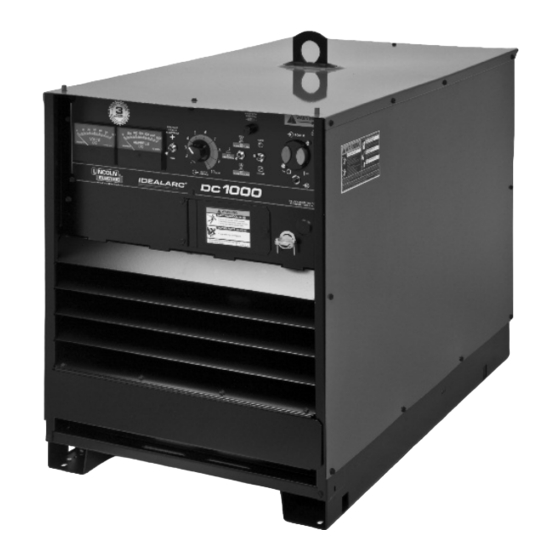
DC-1000
®
For use with machines having Code Numbers:
1248
Need Help? Call 1.888.935.3877
to talk to a Service Representative
Hours of Operation:
8:00 AM to 6:00 PM (ET) Mon. thru Fri.
After hours?
Use "Ask the Experts" at lincolnelectric.com
A Lincoln Service Representative will contact you
no later than the following business day.
For Service outside the USA:
Email: globalservice@lincolnelectric.com
Advertisement
Table of Contents

Related Manuals for Lincoln IDEALARC DC-1000


Summary of Contents for Lincoln IDEALARC DC-1000
- Page 1 8:00 AM to 6:00 PM (ET) Mon. thru Fri. Save for future reference After hours? Use “Ask the Experts” at lincolnelectric.com A Lincoln Service Representative will contact you Date Purchased no later than the following business day. For Service outside the USA: Email: globalservice@lincolnelectric.com...
- Page 2 (See below). SAFETY DEPENDS ON YOU USE NATURAL DRAFTS or fans to keep the fumes away Lincoln arc welding and cutting equipment is designed and built from your face. with safety in mind. However, your overall safety can be increased If you de velop unusual symptoms, see your supervisor.
- Page 3 W117.2-1974. A Free copy of “Arc Welding Safety” booklet E205 is available from the Lincoln Electric Company, 2.d. All welders should use the following procedures in order to 22801 St. Clair Avenue, Cleveland, Ohio 44117-1199.
-
Page 4: Electric Shock Can Kill
SAFETY ELECTRIC SHOCK ARC RAYS CAN BURN. CAN KILL. 3.a. The electrode and work (or ground) circuits are 4.a. Use a shield with the proper filter and cover plates to protect your electrically “hot” when the welder is on. Do eyes from sparks and the rays of the arc when welding or not touch these “hot”... - Page 5 SAFETY WELDING AND CUTTING CYLINDER MAY EXPLODE IF SPARKS CAN CAUSE DAMAGED. FIRE OR EXPLOSION. 7.a. Use only compressed gas cylinders containing the correct shielding gas for the process used 6.a. Remove fire hazards from the welding area. If and properly operating regulators designed for this is not possible, cover them to prevent the welding sparks the gas and pressure used.
-
Page 6: Table Of Contents
TABLE OF CONTENTS Page Installation........................Section A Safety Precautions.......................A-2 Technical Specifications.......................A-1 Location ........................A-2 Input Wiring ........................A-2 Stacking ........................A-2 Reconnect Procedures....................A-3 Output Connections......................A-4 _______________________________________________________________________________ Safety Precautions .......................B-1 Operation.........................Section B Product Description ......................B-1 To Set Polarity........................B-4 thru B-3 Meaning of Symbols .....................B-1 Set-Up For Various Procedures..................B-4, B-5 ________________________________________________________________________________ Maintenance ....................Section D... - Page 7 NOTES IDEALARC® DC-1000...
-
Page 8: Installation
INSTALLATION TECHNICAL SPECIFICATIONS – Idealarc DC-1000 ® INPUT: THREE PHASE ONLY AC INPUT CURRENT (I ) AT RATED OUTPUT (I INPUT AC 1MAX 1EFF FREQUENCY VOLTAGE (U1) AT 1250A 44V 50%DC AT 1140A 44V 60%DC AT 1000A 44V 100%DC 1MAX 1MAX 380V 50/60Hz... -
Page 9: Safety Precautions
INSTALLATION SAFETY PRECAUTIONS This equipment is for industrial use only and it is not intended for use in residential locations where the Read this entire installation section before you electrical power is provided by the public low-voltage start installation. supply system. There can be potential difficulties in residential locations due to conducted as well as radi- WARNING ated radio-frequency disturbances. -
Page 10: Reconnect Procedure
INSTALLATION RECONNECT PROCEDURE To reconnect a multiple voltage machine to a different voltage, remove input power and change the position of the reconnect board on the Reconnect Panel. Multiple voltage machines are shipped connected for Follow The Input Connection Diagram located on the the highest input voltage listed on the machine’s rating inside of Case Back Input Access Door. -
Page 11: Output Connections
INSTALLATION OUTPUT CONNECTIONS Control Cable Connection Output Studs Terminal strips with screw connections are located behind the hinged door on the front of the power The output leads are connected to the output source to make all the control cable connections for terminals. -
Page 12: Operation
OPERATING INSTRUCTIONS OPERATION MEANINGS OF SYMBOLS WARNING The DC-1000 nameplate has been designed to use ELECTRIC SHOCK can kill. international symbols in describing the function of the • Do not touch electrically live parts or various components. Below are the symbols used. electrode with skin or wet clothing. - Page 13 OPERATION ELECTRODE POLARITY SWITCH Positive Electrode Negative Electrode EARTH GROUND CONNECTION ON INPUT BOX Signifying the Earth (Ground) Connection RATING PLATE IEC 60974-1 Designates welder complies with International Electrotechnical Commission requirements 60974-1. Three Phase Power Transformer Rectifier Rectified DC Output Line Connection Flux Cored Arc Welding Submerged Arc Welding IDEALARC...
- Page 14 OPERATION RATING PLATE IP21S Degree of protection provided by the enclosure Designates welder complies with low voltage directive and with EMC directive. Designates welder complies with China Compulsory Certificate C-Tick symbol indicates conformity with Australian EMC regulations. Designates welder complies with IEC 60974-10 -10 Class A Electromagnetic Capability (EMC) requirements for equipment used in industrial locations.
-
Page 15: To Set Polarity
This switch setting is necessary for proper 1. Selection of mode switch position - There are operation of some Lincoln wire feeders and does not change the welding polarity. several general rules to follow in the selection of the mode switch position. - Page 16 OPERATION 5. LN-7, LN-9 and other constant wire feed units - All the NA-3’s when used with the DC-1000 are capable of cold starting with the constant current Set the DC-1000 mode switch on CV Innershield board mode switch in CC. Cold starting permits the or CV Submerged Arc according to the process wire to be inched down to the work, automatically being used.
-
Page 17: Maintenance
MAINTENANCE SAFETY PRECAUTIONS WARNING The control board is designed with adequate protection so that no damage will occur if the remote • Only qualified personnel should ELECTRIC SHOCK can kill. control leads are shorted together or are grounded to perform this installation. the case. -
Page 18: Troubleshooting
HOW TO USE TROUBLESHOOTING GUIDE WARNING Service and Repair should only be performed by Lincoln Electric Factory Trained Personnel. Unauthorized repairs performed on this equipment may result in danger to the technician and machine operator and will invalidate your factory warranty. For your safety and to avoid Electrical Shock, please observe all safety notes and precautions detailed throughout this manual. - Page 19 CAUTION If for any reason you do not understand the test procedures or are unable to perform the tests/repairs safely, contact your Local Lincoln Authorized Field Service Facility for technical troubleshooting assistance before you proceed. IDEALARC® DC-1000...
-
Page 20: Troubleshooting Guide
If connected to an LN-9 or NA-5, disconnect leads 73, 74, 75 before troubleshooting. CAUTION If for any reason you do not understand the test procedures or are unable to perform the tests/repairs safely, contact your Local Lincoln Authorized Field Service Facility for technical troubleshooting assistance before you proceed. IDEALARC® DC-1000... - Page 21 500 amp “+” output stud. 500 amperes. CAUTION If for any reason you do not understand the test procedures or are unable to perform the tests/repairs safely, contact your Local Lincoln Authorized Field Service Facility for technical troubleshooting assistance before you proceed. IDEALARC® DC-1000...
- Page 22 P.C. board. CAUTION If for any reason you do not understand the test procedures or are unable to perform the tests/repairs safely, contact your Local Lincoln Authorized Field Service Facility for technical troubleshooting assistance before you proceed. IDEALARC® DC-1000...
- Page 23 Troubleshooting Guide CAUTION If for any reason you do not understand the test procedures or are unable to perform the tests/repairs safely, contact your Local Lincoln Authorized Field Service Facility for technical troubleshooting assistance before you proceed. IDEALARC® DC-1000...
- Page 24 BRIGHT, REPLACE FIRING P.C. BOARD BE REPLACED CAUTION If for any reason you do not understand the test procedures or are unable to perform the tests/repairs safely, contact your Local Lincoln Authorized Field Service Facility for technical troubleshooting assistance before you proceed. IDEALARC® DC-1000...
- Page 25 DIAGRAMS CONNECTION OF DC-1000 TO LN-8 Connect the control cable ground lead to the frame terminal marked near the power source terminal strip. The power T O L N - 8 I N P U T source must be properly grounded. C A B L E P L U G P O W E R S O U R C E *If using an older control cable: Connect lead #75 to #75 on...
- Page 26 DIAGRAMS CONNECTION OF DC-1000 OR DC-1500 to NA-3, LT-5 or LT-7 Connect the control cable ground lead to the frame terminal marked near the power source terminal strip. The T O A U T O M A T I C power source must be properly grounded.
- Page 27 DIAGRAMS CONNECTION OF DC-1000 to NA-5 N.A. Welding cables must be of proper capacity for the current and duty cycle of immediate and future appli- cations. N.B. Extend lead 21 using #14 (2.5 mm ) or larger insulated wire physically suitable for the installation. An S16586-[ ] remote voltage sensing work lead is available for this T O N A - 5 I N P U T C A B L E P L U G...
- Page 28 DIAGRAMS CONNECTION OF DC-1000 TO LN-7 N.A. Welding cables must be of proper capacity for the current and duty cycle of immediate and future applications. T O L N - 7 I N P U T C A B L E P L U G P O W E R S O U R C E N.B.
- Page 29 DIAGRAMS IDEALARC® DC-1000...
- Page 30 Index of Sub Assemblies - 12480 PART NUMBER DESCRIPTION P-720-A Index of Sub Assemblies P-720-B.2 Miscellaneous Items P-720-C_2 Case Front & Control Box P-720-D Case Back Assembly P-720-E Base Fan Roof and Case Sides P-720-F Output Rectifier & Choke Assembly P-720-G Lift Bale &...
- Page 31 Index of Sub Assemblies - 12480 P-720-A.jpg DC-1000 - 12480...
- Page 32 Miscellaneous Items PART NUMBER DESCRIPTION 9ST13260-4 DECAL-EARTH GROUND CONN 9ST14798-1 IDENTIFICATION STICKER (CR1) 9SS13504 DECAL-CAUTION 9ST13470-3 DECAL-WARNING 9SL8064-1 WARNING DECAL (INTERNATIONAL) 9ST14753 INSTRUCTION DECAL 9ST13259-4 GROUNDING DECAL DC-1000 - 12480...
- Page 33 Miscellaneous Items No Image DC-1000 - 12480...
- Page 34 Case Front & Control Box PART NUMBER DESCRIPTION 9SL7521-15 CASE FRONT WELDED ASBLY 9SL7517-1 CASE FRONT SUPPORT 9SL7517-2 CASE FRONT SUPPORT 9SL9006 CONTROL BOX WELDED ASBLY 9SM15391-2 LOUVER 9SM15391-3 LOUVER 9SL9005 OUTPUT PANEL 9SS8025-91 SELF TAPPING SCREW 9SM17097 OUTPUT STUD COVER ASBLY 9SS8025-92 SELF TAPPING SCREW 9SS8025-92...
- Page 35 Case Front & Control Box PART NUMBER DESCRIPTION 9SS8025-92 SELF TAPPING SCREW 9ST13260-4 DECAL-EARTH GROUND CONN 9SS20641 OUTPUT TERMINAL DECAL 9SS17160 NUMBER PLATE 9SS8025-15 SELF TAPPING SCREW 9SS8025-62 SELF TAPPING SCREW 9ST14689 TERMINAL STRIP GASKET 9SS8542-7 TERMINAL STRIP 9SS14530-11 TERMINAL STRIP 9SL9000 CONTROL BOX COVER 9SL8237-3...
- Page 36 Case Front & Control Box PART NUMBER DESCRIPTION 9ST4291-B LOCKWASHER 9ST13597-1 PLUG BUTTON 9ST9639-1 CLAMP 9SS17293 ACCESS DOOR ASBLY 9SS8025-65 SELF TAPPING SCREW 9SS27359 METER SPACER 9ST13486-2 PILOT LIGHT DC-1000 - 12480...
- Page 37 Case Front & Control Box P-720-C_2.jpg DC-1000 - 12480...
- Page 38 Case Back Assembly PART NUMBER DESCRIPTION 9SM13544 STATIONARY RECONNECT PANEL ASBLY 9SS8025-92 SELF TAPPING SCREW 9ST10082-3 SEMS SCREW 9SCF000010 #10-24HN 9ST10940-4 HEX JAM NUT 9SS9262-4 PLAIN WASHER 9SS16215 MOVABLE RECONNECT PANEL ASBLY 9ST14190 RECONNECT PANEL LINK 9ST14723 PRI CONNECTION LEAD 9SCF000017 1/4-20HN 9SS9262-98...
- Page 39 Case Back Assembly PART NUMBER DESCRIPTION 9SCF000017 1/4-20HN 9SM12390-21 TRANSFORMER ASBLY 9SS8025-91 SELF TAPPING SCREW 9SS9262-121 PLAIN WASHER 9SCF000029 5/16-18HN 9SS24579-15 Rating Plate 9SM12390-72 TRANSFORMER ASBLY DC-1000 - 12480...
- Page 40 Case Back Assembly P-720-D.jpg DC-1000 - 12480...
- Page 41 Base, Fan, Roof and Case Sides PART NUMBER DESCRIPTION 9SL6598-1 BASE WELDED ASBLY 9SL6247 FAN BAFFLE 9SS8025-65 SELF TAPPING SCREW 9SM6819-12 9SCF000011 10-32HN 9SCF000042 #8-32HN 9SE106A-1 LOCKWASHER 9SS9262-27 PLAIN WASHER 9SM9983-6 FAN MOTOR 9SM16525-2 FAN MOTOR MOUNTING BRACKET 9SS8025-110 SELF TAPPING SCREW 9SM12352-17 ROOF ASBLY 9SS8025-65...
- Page 42 Base, Fan, Roof and Case Sides P-720-E.jpg DC-1000 - 12480...
- Page 43 Output Rectifier & Choke Assembly PART NUMBER DESCRIPTION 9SM16986 OUTPUT RECTIFIER ASBLY 9SM14604-1 SCR HEAT SINK ASBLY 9SS17163 SNUBBER ASBLY 9SS17154 HEAT SINK MTG BRKT ASBLY 9SS9262-4 PLAIN WASHER 9SE106A-16 LOCKWASHER 9SCF000067 3/8-16HN 9SM14286-3 LEAD (SHUNT TO RECTIFIER) 9SM14286-4 LEAD (SHUNT TO RECTIFIER) 9SS8025-12 SELF TAPPING SCREW 9SCF000105...
- Page 44 Output Rectifier & Choke Assembly P-720-F.jpg DC-1000 - 12480...
- Page 45 Lift Bale & Transformer Assembly PART NUMBER DESCRIPTION 9SL6600 LIFT BALE ASBLY 9SS10404-118 RESISTOR-WW300W3010% 9ST9781-34 THRU BOLT 9ST9764-6 INSULATOR 9SS9262-98 PLAIN WASHER 9SE106A-2 LOCKWASHER 9SCF000017 1/4-20HN 9SS17301 LIFT BALE BAFFLE 9SS9225-26 THREAD FORMING SCREW (ROLLING) 9SS9225-26 THREAD FORMING SCREW (ROLLING) 9ST9781-45 MOUNTING STUD 9SE106A-5...
- Page 46 Lift Bale & Transformer Assembly PART NUMBER DESCRIPTION 9SL6616-7 TRANSFORMER AND LIFT BALE ASBLY 9SL9002-4 Complete Transformer Assembly 9SS16333 PRI-SEC INSULATION 9SS17156-1 TRANS SIDE BRACKET 9SS17156-2 TRANS SIDE BRACKET 9SS16090-3 MISC. FLAT DC-1000 - 12480...
- Page 47 Lift Bale & Transformer Assembly P-720-G.jpg DC-1000 - 12480...
- Page 48 S78 Contactor PART NUMBER DESCRIPTION 9SL6200-36A CONTACTOR ASBLY-W/O NVR COIL 9SS12851 MOVING LAMINATION ASBLY 9ST9031 SCREW 9ST9695-1 LOCKWASHER 9SE106A-1 LOCKWASHER 9SCF000011 10-32HN 9SS1-9 NVR COIL 9SM6888-9 MTG PANEL ASBLY 9SS10425 GUIDE 9SM13771 CONTROL BLOCK COVER 9SS9262-121 PLAIN WASHER 9ST9187 LOCKNUT 9ST9453 INTERLOCK BLOCK ASBLY 9SM6893-45...
- Page 49 S78 Contactor P-720-H.jpg DC-1000 - 12480...
- Page 50 WARNING Do not touch electrically live parts or Keep flammable materials away. Wear eye, ear and body protection. electrode with skin or wet clothing. Insulate yourself from work and AVISO DE ground. Spanish PRECAUCION No toque las partes o los electrodos Mantenga el material combustible Protéjase los ojos, los oídos y el bajo carga con la piel o ropa...
- Page 51 WARNING Keep your head out of fumes. Turn power off before servicing. Do not operate with panel open or Use ventilation or exhaust to guards off. remove fumes from breathing zone. AVISO DE Spanish PRECAUCION Los humos fuera de la zona de Desconectar el cable de No operar con panel abierto o respiración.
- Page 52 Lincoln Electric for advice or information about their use of our products. We respond to our customers based on the best information in our possession at that time. Lincoln Electric is not in a position to warrant or guarantee such advice, and assumes no liability, with respect to such information or advice.
Need help?
Do you have a question about the IDEALARC DC-1000 and is the answer not in the manual?
Questions and answers