Table of Contents
Advertisement
Quick Links
Advertisement
Table of Contents

Subscribe to Our Youtube Channel
Related Manuals for Huvema HU 16 SUPER


Summary of Contents for Huvema HU 16 SUPER
- Page 1 D R I L L I N G M A C H I N E S HU 16 SUPER...
-
Page 2: Table Of Contents
able of conTenTs General safety rules for all machines Additional safety rules Unpacking Transportation instruction Features Installing the machine Main parts Control panel T-grooves Work table adjustment 7.2.1 Height adjustment 7.2.2 Angle adjustment 7.2.3 360 Turning Drill depth adjustment Speed Selection V belt adjustment Noise levels Troubleshooting... -
Page 3: General Safety Rules For All Machines
hU 16 s rilling machine Uper 1. g eneral safeTy rUles for all machines N.B.: Read the instructions carefully in order to avoid any problems. As with all machinery there are certain hazards involved with operation and use of this machine. Using the machine with respect and caution will considerably lessen the possibility op personal injury. -
Page 4: Additional Safety Rules
2. a DDiTional safeTy rUles Always keep in mind that: • the machine must be switched off and disconnected from the power supply during maintenance and repairs, • clamped workpieces may only be measured when the machine is switched off. Never lean over the machine, mind loose clothing, ties, jewellery etc. -
Page 5: Features
4. f eaTUres Model HU 16 Super Drilling capacity 16 mm Spindle taper Distance column-spindle 180 mm Drilling depth 80 mm Speed range 300-2360 rpm (12) Max. distance spindle-table 510 mm Column diameter 80 mm Motor power 0.75 kW Weight... -
Page 6: Main Parts
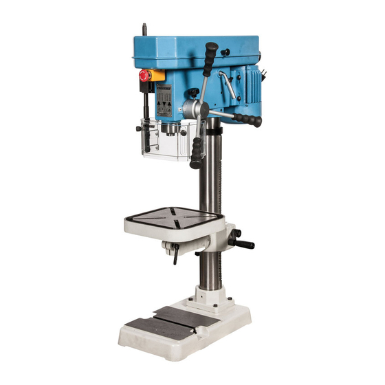
JTD-16series Figure 4 6. m ain parTs Pulley cover Emergency stop Handle v belt tension Head Motor Feed handle Drill head Column Chuck guard Rack Table Table height adjustment Base Figure 5 CHANGES AND T YPING ERRORS RESER VED CHANGES AND T YPING ERRORS RESER VED... -
Page 7: Control Panel
3-1. Control panel instruction: 7. c onTrol panel Figure 6 • Check the power source. Push the start button to check if the motor and spindle shaft are in normal working condition. 3-2. Operation illustration and procedure: • In case of an emergency, push the emergency stop. 7.1 T- 1. -
Page 8: Drill Depth Adjustment
4. Adjustment of feeding limit 7.3 D rill DepTh aDjUsTmenT To prevent unwanted penetration to work piece, the feeding limit To prevent the drill from going too deep into the work piece, you can set shall be set by adjusting the appropriate position of feeding depth the feeding limit by adjusting the position of the feed depth knob fixing button as long as the distance between the end of tool and (A, figure 8). -
Page 9: Belt Adjustment
JTD-16S A-42 Belt specifications Quantity Machine model Belt specifications Quantity JTD-16SA A-25 / A-26 A-42 HU 16 Super A-25/A-26 Models belt model tables 7.6 n A-25 / A-26 oise levels Machine model Belt specifications Quantity Noise level with no load: Lpa = 62 dB(A) -
Page 10: Troubleshooting
8. T roUbleshooTing Switch off power and remove plug from power source outlet before trouble shooting. Problem Solution Drill is caught in the work piece and the spindle 1. Push the emergency button has stopped 2. Turn off the power 3. Turn the spindle manually counterclockwise to withdraw the tool from the work piece 5-1. -
Page 11: Dimensions
• Engage the next available spring cover lock slot and push the spring lock cover back. • Retighten the lock nut and replace the cover. 10. D imensions Dimensions(m/m) All dimensions in mm. JTD-16 HU 16 Super series 1030 C=470×c1=280 D=280 × d1=280 Figure 15... -
Page 12: Control Circuit Diagram
7.Control circuit diagram and component part list; 11. c onTrol circUiT Diagram Figure 16 Symbol Function Tech. data Remark Motor DC230V / 1 PH / 1.2 kW/8A Speed adjustment knob DC10V B203 Part No. Component/Object Manufacturer Relais AC250V 12A Motor AC230V or 400V ON button AC250V 12A... -
Page 13: Parts Drawing And List
8.Drawing and parts list; 12. p arTs DraWing anD lisT Figure 17 CHANGES AND T YPING ERRORS RESER VED... - Page 14 101-S3 LEAD BOLT JTD-16 series SAFETY GUARD QUILL 102A SAFETY GUARD SLIDE RUBBER WASHER BASE 102-S1 SCREW SPINDLE COLUMN HOLDER 102-S2 LEAD BOLT BALL BEARING 2-S1 BOLT BRACKET ROD THRUST BEARING 103A SUPPORT ARM 2-S2 SPRING WASHER BALL BEARING 103B LOWER BRACKET ROD COLUMN SPINDLE NUT...
-
Page 15: Ce Declaration Of Conformity
(in accordance with supplement II, section 1A of the Machinery Directive) Industrie & Handelsonderneming Huberts bv, Kennedylaan 14, 5466 AA Veghel, the Netherlands, in the capacity of importer, is to be held responsible for declaring that the Huvema machine: Drilling machine HU 16 Super...
Need help?
Do you have a question about the HU 16 SUPER and is the answer not in the manual?
Questions and answers