
Subscribe to Our Youtube Channel
Related Manuals for Gamma 7500 Els


Summary of Contents for Gamma 7500 Els
- Page 1 7500 Els STRINGING MACHINE OWNER'S MANUAL Issue 3 - December 18, 2000 Copyright 2000 GAMMA Sports - All Rights Reserved Provided by www.gssalliance.com...
-
Page 2: Table Of Contents
To return defective EQUIPMENT, a return authorization (RA#) must be obtained from a GAMMA customer service representative by calling 1-800-333-0337. The RA# must be marked on the outside of the shipping carton being returned. All returns must be shipped prepaid by the customer to GAMMA. Please retain... -
Page 3: Features
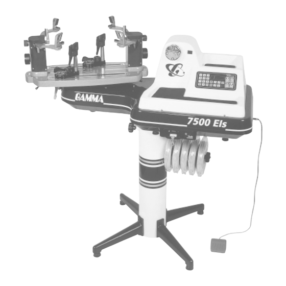
7500 Els Key Product Features 1. Electric Constant Pull String Tensioner w/ Diamond Coated String Gripper (10-90 lbs tension range in 0.10 lbs increments) 2. Electronic Control Panel w/ Keypad, Knot, Prestretch, & String Length Functions 3. String Reel Holder 4. - Page 4 Instructions for Unpacking and Preparing for Assembly The 7500 Els is shipped in two cartons, a large carton for the stringing machine and accessories and a smaller carton for the post and base legs. Please save the cartons and packing materials for possible shipments in the future.
-
Page 5: Assembly Instructions
Assembly Instructions Base Leg Assembly The stringing machine uses a four leg base design. The legs must be assembled to the support post before use. Remove the lower column support, the upper column support, four (4) legs, four (4) socket head cap screws and four (4) flat head cap screws from the small shipping carton. - Page 6 Assembly Instructions Unpacking the Tensioner Assembly The tensioner assembly is packed inside the inner carton and is bolted to a sheet of wood with four (4) bolts to prevent damage during shipment. Another sheet of wood is bolted to the underside of the inner carton through the first piece of wood.
- Page 7 Assembly Instructions Stand Upper Post Installation (cont.) With the height adjustment cap screw on the upper post facing the right side of the tensioner, align the four (4) holes in the upper post flange with the holes in the tensioner base. Secure the flange to the base with the four cap screws.
- Page 8 Assembly Instructions Installing the Racquet Mounting System Align the threaded hole in the bottom of the frame support post with the slot in the turntable. Screw the lever lock bolt with washer into the center hole located in the bottom of the support post and loosely tighten. Position the washer with the rounded edge toward the turntable.
- Page 9 String Reel Holder Installation The string reel holder pin is an 8 mm rod with threads on both ends, and flat surfaces machined on one end. Thread the end of the pin without the flat surfaces into the threaded boss on the right side of the lower column support.
- Page 10 SLM Face Plate Installation Remove the tape covering the opening on the front side of the bottom cover to expose the string length meter. Position the face plate assembly over the opening in the bottom cover, and align the two countersunk end holes of the face plate with the threaded attachment holes in the front of the string length meter.
- Page 11 Power Connection & Controls Instructions for Power Connection (Refer to Figure 1) CAUTION ! Before connecting to the power supply, check the voltage supply switch setting located on the side panel as shown in Figure 1. To change from 110 volts service to 220 volt service simply slide the switch fully to the top or to the bottom until “110V”...
-
Page 12: Control Panel Functions And Features
Control Panel Functions and Features Keypad - Used to enter tension settings Single Digit (0-4) Three Digit (XX.X) Tension Settings or String Length Memory LED Display LED Display Release Button - Returns winder to starting position and releases tension Tension Index Buttons - Changes tension setting Memory Button - Indexes from 4 preset tension in +/- 1.0 or 0.1 Lb or Kg increments. -
Page 13: String Length Meter Operation
String Length Meter Operation To enable the String Length Meter (SLM) function, press the String Length function key on the keypad. When the String Length button is pressed, one of the Red LED indicators below “M” or “FT” will light up to indicate that the SLM function is enabled. -
Page 14: Cam-Lock Clamp Operation
Cam-Lock Clamp Operation Clamp Head Operation To clamp a string, lift the clamp head and place the string between the jaws and depress the clamp head lever to secure the string. The clamping pressure applied to the string should be adjusted to provide sufficient pressure to secure the string when subjected to the desired pulling tension. -
Page 15: String Gripper / Tensioner Operation
String Gripper Operation String Gripper Operation To insert the string in the split drum string gripper, wrap the free end of the string clockwise around the gripper drum and position the string between the gripper jaws as shown in the illustration. The string must pass over the top half of the gripper before being placed between the diamond coated plates of the upper and lower gripper jaws. -
Page 16: Mounting The Frame
Mounting the Frame Adjusting the Frame Support Posts Place the racquet frame over the center support slide and onto the frame support. Loosen the lever lock bolt on one support post. Slide the post outward until the center support of the racquet support slide is positioned near the inside surface of the racquet frame. -
Page 17: Stringing The Frame
Mounting the Frame Support Slide Adjustment Once the frame support posts are secured, lightly tighten the support slides by turning the knobs on the outside of the slides clockwise. Adjust the slides in equal incre- ments until slight resistance is felt. Apply a final adjustment to all racquet support points until the racquet is firmly secured in the mounting system. -
Page 18: Pathfinder Awl Operation
Pathfinder Awl Operation The machine includes the new Pathfinder stringing awl which creates a pathway between or around strings to make inserting a string through tight grommets easier and quicker. Insert the awl through the grommet hole in the same manner as for traditional awls. - Page 19 +/- 5 lbs from the factory settings. If the difference between the measurement from the calibrator and the tension setting is more than 5 lbs. call the machine service department of GAMMA Sports at 1-800-333-0337 for assistance.
- Page 20 Cleaning Instructions for String Clamps To thoroughly clean the diamond coated surfaces of the clamp heads, remove the adjustment knob screw, lever plate, and compression spring to expose the inside surfaces of the clamps. Using the cleaning stone pro- vided with your machine (you can also use a small tooth brush or a sharpening stone for knives), scrub the diamond coated plates until all debris is removed.
-
Page 21: Troubleshooting Tips
If it is burned out, replace it with the spare fuse and replace the fuse holder in its socket. Supply power to the machine and check for proper operation. If problems persist, contact Gamma Sports Customer Service at 1-800-333-0337... - Page 22 7500 Els Parts Summary Inside Cover Inside Cover 122A...
- Page 23 Cam Lock Base/Glide Bar Assy Cam Lock Clamp Base Die Cast Gripper Jaw Assy Lower Column (w/RH Reel Hold) TT Brake Lever Reel Holder Bolt Reel Holder Spacer Reel Holder Knob 7500 Els Tensioner Module 7500 Upper Tray Pad 7500 Lower Tray Pad...
Need help?
Do you have a question about the 7500 Els and is the answer not in the manual?
Questions and answers