Table of Contents
Advertisement
Quick Links
Advertisement
Table of Contents

Related Manuals for Gamma 9900 Els


Summary of Contents for Gamma 9900 Els
- Page 1 9900 Els STRINGING MACHINE 2 PT SC MOUNTING OWNER’S MANUAL Issue 1 - June 2015...
-
Page 2: Table Of Contents
(excluding electrical parts and string clamps), and for a period of one (1) year from the date of purchase for all electrical parts and string clamps. Should any defects develop under normal use within the specifi ed time periods, GAMMA will at its option, repair or replace the defective EQUIPMENT provided it is returned to GAMMA prepaid at the purchaser’s expense. -
Page 3: Features
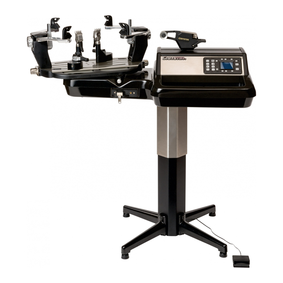
MACHINE FEATURES MACHINE FEATURES Electric Constant Pull Tensioner with 11.0 to 90.0 lbs Tension Range Digital Tension Setting with LCD Display Auto Start Quick Closing Linear String Gripper Professional Two Point Self Centering Racquet Mounting System- Accommodates All Racquets ... - Page 4 fl oor stand post and base legs. Please save the cartons and packing materials for possible shipments in the future. Gamma Sports cannot be responsible for machines that are not returned, shipped in their original, undamaged packaging.
- Page 5 ASSEMBLY INSTRUCTIONS Floor Stand Leg Assembly The stringing machine uses a four leg fl oor stand design. The legs must be assembled to the Lower Column before use. Remove all parts from the shipping carton to confi rm that contents match the parts list. Align the holes in the Leg Flange with the matching holes in the Lower Column.
- Page 6 ASSEMBLY INSTRUCTIONS Floor Stand Power Connection Plug the Floor Stand power cord from bottom left side of the tensioner housing into the socket on the Floor Stand column. Floor Stand Height Adjustment The electric fl oor stand permits height adjust- ments from 39”...
- Page 7 ASSEMBLY INSTRUCTIONS AC Power Adapter Storage Shelf The AC Power Adapter Storage Shelf pro- vides a means to secure and protect the power adapter by storing it safely under the machine base. This will reduce a potential tripping hazard as well as eliminate potential damage to the AC Power Supply if laying on the fl...
- Page 8 ASSEMBLY INSTRUCTIONS String Reel Installation The String Reel Holder pin is an 8 mm rod with threads on both ends and fl at surfaces machined on one end. Thread the end of the pin without the fl at surfaces into the threaded boss on the right side of the Lower Column.
- Page 9 ASSEMBLY INSTRUCTIONS Turntable and Mounting System Installation To install the Turntable position the Turntable over the turntable pin and align the holes in the turntable with the holes in the turntable pin. Insert the bolts through the holes in the turntable and turntable pin and tighten with an M6 hex wrench.
-
Page 10: Power Connection & Controls
POWER CONNECTION & CONTROLS Front Panel Features A - String Gripper B - Tension Lever Switch C - Control Panel with LCD Display Back Panel Features D - Power Switch E - A/C Power Cord Socket F - Foot Pedal Switch Socket G - Floor Stand Power Socket Instructions for Power Connection and Controls CAUTION ! Before connecting to the power supply, check the voltage source that the... - Page 11 CONTROL PANEL FEATURES ENTER Button - Press to confi rm and ESC Button - Press to return to the Stringing Screen from the Settings save changes to any machine settings and to zero the String Length Meter. Screen, String Length Meter Screen or to cancel a change being made to one of the functional settings.
-
Page 12: Display Screen
DISPLAY SCREENS Language Selection Screen At start-up, if a language other than English is desired, press any one of the F6-F8 buttons when the Start-up Screen appears to change to the Language Selection Screen. Press- ing any one of the F2-F8 buttons will scroll through the available languages. -
Page 13: Machine Functions
MACHINE FUNCTIONS Setting Tension To change the Tension Setting press F2 to increase the Tension Setting in the tens place, F3 to increase the Tension Setting in the units place and F4 to increase the Tension Setting in the tenths place. To decrease the Tension Setting press F6 to decrease the Tension Setting in the tens place, F7 to decrease the Tension Setting... - Page 14 MACHINE FUNCTIONS Permanent Memory Settings There are 9 permanent Memory Settings that can be used to store 9 combinations of machine settings. Pressing the MEMORY button will scroll through the 9 Memory Settings in increasing order. To reverse the scrolling order, press the F5 button. The Blue LED will illuminate and the scrolling order will be in decreasing order.
- Page 15 MACHINE FUNCTIONS Setting the Pulling Speed from the Stringing Screen To change the Pulling Speed Setting while in the Stringing Screen, fi rst press the PULLING SPEED button to display the Pull- ing Speed Icon and Pulling Speed Setting on the display. Then press and hold the PULLING SPEED button again until the Pulling Speed Setting is highlighted above the Pulling Speed Icon.
- Page 16 MACHINE FUNCTIONS Pre-stretch Function The Pre-stretch function is used to pre- stretch strings by increasing the applied tension by a set percentage over the tension setting before releasing the string and re- pulling to the desired tension. This function helps to reduce the amount of tension loss in the strings over time.
- Page 17 MACHINE FUNCTIONS Knot String Function The Knot String function is used to increase the applied tension by a set percentage over the tension setting on the last main string or cross string pulled before tying off. This function helps to compensate for tension loss caused by the slack portion of the string from the string clamp to the tie-off knot.
-
Page 18: String Gripper Operation
STRING GRIPPER OPERATION Auto-Start Quick Closing String Grip- per Operation The Quick Closing gripper will automatically tension string without the need to press a ten- sion lever or button. To tension a string, wrap the string clockwise around the string guide and insert the string between the string gripper plates. -
Page 19: Mounting The Frame
MOUNTING THE FRAME Mounting Stand Adjustment When mounting a racquet, adjust the Mounting Stands so that the white Racquet Supports on top of the Mounting Stands fi t inside the hoop of the racquet. Lower the racquet over the Racquet Supports and adjust the Mounting Stands until the sup- ports just make contact with the inside sur- face of the racquet at the head and throat. - Page 20 MOUNTING THE FRAME Special Throat Mounting Racquets with a bridge that is thinner than the rest of the frame or are tapered from head to throat require special mounting to ensure the frame is not damaged. The white Support Pads need to be moved from the inside of the racquet bridge to the throat of the racquet.
-
Page 21: Stringing The Frame
STRINGING THE FRAME Stringing the Mains Follow the manufacturer’s recommended stringing pattern for one or two piece stringing. To determine which end of the racquet to start installing the string count the number of grommet holes located in the throat bridge. If there are 2 or 6 holes start main strings at the center 2 holes of the throat bridge. - Page 22 STRINGING THE FRAME As tension is applied to the string, the 4 Tension Indicator LEDs on the Control Panel will progres- sively fl ash until all 4 are lit indicating that the set tension has been reached. The 4 LEDs will remain lit and the Gripper will continue to pull to maintain the set tension in the string until the string is clamped off and the tension is released.
- Page 23 STRINGING THE FRAME Clamping the First Main String Secure the tensioned main string using the remaining fi xed clamp. Repeat the procedure for all of the remaining main strings and tie off at the appropriate holes following the racquet manufacturers specifi cations. This will determine the starting point for the cross strings.
-
Page 24: String Length Meter
STRING LENGTH METER OPERATION String Length Meter Press the String Length Meter (SLM) button to enable the SLM function and display the SLM screen. To change the measurement units from Feet (FT) and meters (M) press the SLM button to toggle between FT and M. To measure a length of string from a reel or set of string, insert the end of the string through the loop from the backside of the string... -
Page 25: Additional Features
ADDITIONAL FEATURES Turntable Brake The Turntable may be locked in any position. To lock the Turntable Brake pull the brake lock pin OUT. To release the Turntable Brake push the brake lock pin IN. Turntable Clutch To adjust the free rotation of the turntable, turn the Turntable Clutch bolt located on the left end of the base clockwise to add friction and restrict rotation or turn the Turntable Clutch... -
Page 26: Pathfinder Awl
PATHFINDER AWL The machine includes the Pathfi nder String- ing Awl which creates a pathway between or around strings to make inserting a string through blocked grommets easier and quicker. Insert the awl through the grommet hole in the same manner as for traditional awls. The Pathfi... -
Page 27: Maintenance & Adjustments
MAINTENANCE & ADJUSTMENTS Tension Calibration Procedure During power up press both ESC and ENTER buttons to enable the calibra- tion mode. The display will show 22 lbs or 10 kgs. KG/LBS can be changed at any time by pressing the LB/KG Button. Using a Tension Calibrator, apply tension to the calibrator and adjust the value on the display up or down to match the reading on... - Page 28 MAINTENANCE & ADJUSTMENTS Auto-Release Clamp Base Adjust- ment If the Clamp Bases slip on the Turntable, the base locking levers may need adjusted. Turn the cap screw located on the end of the Clamp Base clockwise to increase clamping pressure and counterclockwise to reduce it. If frequent adjustment is needed, try loos- ening the Locking Lever Adjustment Screw and tighten the two screws located on the...
-
Page 29: Troubleshooting Tips
TROUBLESHOOTING TIPS PROBLEM SOLUTION String slips in clamps - Adjust gap between clamp jaws - Clean clamp jaws String slips in gripper - Adjust gripper jaw stop screw - Clean gripper jaws String clamp base slips on turntable - Clean bottom of clamp & top of turntable with alcohol - Adjust clamp base locking nut String tension too tight or too loose... -
Page 30: Parts List
2 PT STICKER AUTO-START QUICK GRIPPER 9900 ELS TENSIONER 9900 TENSIONER LEFT SIDE CAP 9900 TENSIONER RIGHT SIDE CAP OPTIONAL TOOLS & ACCESS 9900 ELS FRP UPPER COVER MFSC FLOOR STAND CASTERS 9900 ELS BASE FRAME CALIBRATOR 9900 ELS FRP LOWER COVER SGSM STRINGER’S MAT... -
Page 31: Parts Drawing
PARTS DRAWING MMSC13 MARC10... - Page 32 MMAN-53 (MG992-10) GAMMA SPORTS 200 Waterfront Drive Pittsburgh, Pennsylvania 15222 Phone: 800.333.0337 Fax: 412.323.0317 Visit our website at www.gammasports.com Copyright 2015 GAMMA Sports - All Rights Reserved...
Need help?
Do you have a question about the 9900 Els and is the answer not in the manual?
Questions and answers