
Related Manuals for Magnetrol ECLIPSE 700GWR


Summary of Contents for Magnetrol ECLIPSE 700GWR
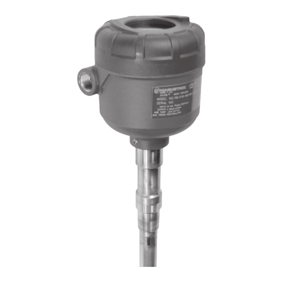
- Page 1 HART ® Installation and Operating Manual for Eclipse ® Model 700 Software Version 1.x Guided Wave Radar Level Transmitter...
- Page 2 International, ® cautions, and warnings. Incorporated. All rights reserved. MAGNETROL reserves the right to make changes to NOTES the product described in this manual at any time with- Notes contain information that augments or clarifies out notice. MAGNETROL makes no warranty with an operating step.
-
Page 3: Table Of Contents
Eclipse Model 700 Guided Wave Radar Transmitter ® Table of Contents 1.0 QuickStart Installation 2.6.2.1 Navigating the Menu......20 1.1 Getting Started............5 2.6.2.2 Data Selection ........20 1.1.1 Equipment and Tools ........5 2.6.2.3 Entering Numeric Data Using 1.1.2 Configuration Information......6 Digit Entry..........21 1.2 QuickStart Mounting..........7 2.6.2.4 Entering Numeric Data 1.2.1 Transmitter/Probe ..........7... - Page 4 3.4 Configuration Information ........49 4.0 dvanced Configuration/Troubleshooting Techniques 3.4.1 Level Offset Description.......49 4.1 End-of-Probe Analysis (EOPA) ........80 3.4.2 End-of-Probe Analysis ........50 4.1.1 Enable EOPA using PACTware .....80 3.4.3 Echo Rejection ..........51 4.1.2 Enable EOPA using keyboard/LCD....81 3.4.4 Volumetric Capability ........51 4.2 Sloped Threshold .............82 3.4.4.1 Configuration using built-in 4.3 Echo Rejection ............84...
-
Page 5: Quickstart Installation
QuickStart Installation The QuickStart Installation procedures provide an overview of the key steps required for mounting, wiring, and config- uring the ECLIPSE Model 700 Guided Wave Radar level transmitter. These procedures are intended for more experi- enced installers of ECLIPSE transmitters (or other electron- ic level measurement instruments). -
Page 6: Configuration Information
1.1.2 Configuration Information To utilize the QuickStart menu available on the ECLIPSE Model 700, some key information is required for configuration. Gather the information and complete the following operating parameters table before beginning configuration. NOTES: The QuickStart menu is available for Level Only applications. 1. -
Page 7: Quickstart Mounting
QuickStart Mounting Ensure that the configuration style and process connection size/type of the ECLIPSE transmitter and probe matches the requirements of the installation before continuing with the QuickStart installation. NOTE: To avoid moisture ingress in the housing, covers should be fully ¡... -
Page 8: Quickstart Wiring
QuickStart Wiring WARNING Possible explosion hazard. Do not connect or discon- nect equipment unless power has been switched off and the area is known to be non-hazardous. NOTE: Ensure that the electrical wiring to the ECLIPSE Model 700 transmitter is complete and in compliance with all local regula- tions and codes. - Page 9 2. The 4-button directional keypad offers multiple forms of functionality for menu navigation and data entry. (See STEP 4 Section 2.6 for complete explanation.) ▲ UP moves up through the menu or increases a displayed value. DOWN moves down through the menu or decreases a displayed value.
-
Page 10: Quickstart Menu Options
1.4.1 QuickStart Menu Options Level Units Select the Units of measurement for the level readout: • Inches • Feet • Millimeters • Centimeters • Meters Probe Model Select the Probe Model to be used with Model 700: • 7zF Single Rod •... -
Page 11: Quickstart Numerical Data Entry
1.4.1.1 QuickStart Numerical Data Entry To make numerical entry changes to Probe Length and Level Offset: ▲ UP moves up to the next highest digit (0,1,2,3,..,9 or the decimal point). If held down the digits scroll until the push button is released. -
Page 12: Complete Installation
For same reason, conduit entries should be properly sealed. Electrostatic Discharge (ESD) Handling Procedure MAGNETROL electronic instruments are manufactured to the highest quality standards. These instruments use elec- tronic components that may be damaged by static electricity present in most work environments. -
Page 13: Before You Begin
• Use a grounding wrist strap when installing and removing circuit boards. A grounded workstation is recommended. • Handle circuit boards only by the edges. Do not touch components or connector pins. • Make sure that all electrical connections are completely made and none are partial or floating. -
Page 14: Mounting
2.4 Mounting An ECLIPSE Model 700 GWR probe can be mounted on to a tank using a variety of process connections. Generally, either a threaded or flanged connection is used. For infor- mation about the sizes and types of connections available, see Probe Model Numbers, Section 3.7.2. -
Page 15: To Install A Coaxial Probe
2.4.1.1 To install a coaxial probe: 1. Ensure that the process connection is the correct threaded or flanged mounting. 2. Carefully place the probe into the vessel. Properly align the gasket on flanged installations. 3. Align the probe process connection with the threaded or flanged mounting on the vessel. -
Page 16: To Install A Rigid Single Rod Probe
2.4.2.1 To install a rigid single rod probe: 1. Ensure that the process connection is at least 1" NPT or is a flanged mounting. 2. Carefully place the probe into the vessel. Align the gasket ➃ ➀ on flanged installations. ➁... -
Page 17: Wiring
Wiring Caution: The ECLIPSE Model 700 transmitter operates at voltages of 11–36 VDC. Higher voltages will damage the transmitter. Wiring connections between the power supply and the ECLIPSE Model 700 transmitter should be made using 18–22 AWG shielded twisted pair instrument cable. Connections are made to the terminal strip and the ground connections beneath the LCD module. -
Page 18: Intrinsically Safe
2.5.2 Intrinsically Safe An Intrinsically Safe (IS) installation potentially has flam- mable media present. An approved IS barrier must be installed in the non-hazardous (safe) area to limit the avail- able energy out to the hazardous area. See Agency Drawing – Intrinsically Safe Installation, Section 3.5.2. -
Page 19: Configuration
Configuration Although the ECLIPSE Model 700 transmitter can be delivered pre-configured from the factory, it can also be easily reconfigured in the shop or at the installation using the local LCD/Keypad or PACTware/DTM. Bench config- uration provides a convenient and efficient way to set up the transmitter before going to the tank site to complete the installation. -
Page 20: Menu Traversal And Data Entry
2.6.2 Menu Traversal and Data Entry The 4-button directional keypad push buttons offer vari- ous forms of functionality for navigation and data entry. The Model 700 user interface is hierarchical in nature, best described as a tree structure. Each level in the tree contains one or more items. -
Page 21: Digit Entry
2.6.2.3 Entering Numeric Data Using Digit Entry This method is used to input numeric data, e.g., Probe Length, set 4mA and set 20mA. Push button Keystroke Action ▲ Moves up to the next highest digit (0,1,2,3,..,9 or decimal point). If held down the digits scroll until the push button is released. -
Page 22: Entering Character Data
2.6.2.5 Entering Character Data This method is used for parameters requiring alphanumer- ic character entry, such as for entering tags, etc. General Menu Notes: Push button Keystroke Action ▲ Moves to the previous character (Z...Y...X...W). If held down, the characters scroll until the push button is released. -
Page 23: Model 700 Menu: Step-By-Step Procedure
dvanced Password Certain portions of the menu structure that contain more advanced parameters are further protected by an Advanced Password. This password will be provided, when necessary, by Factory technical support. Factory Password Calibration-related and other factory settings are further protected by a Factory Password. - Page 24 M IN MENU Pressing any key on the Home Screen will present the Main Menu, consisting of three basic menu labels shown in all capital letters. • DEVICE SETUP • DI GNOSTICS • ME SURED V LUES As shown, the reverse video represents a cursor identifying the selected item, which will appear in reverse video on the LCD.
-
Page 25: Model 700 Configuration Menu - Device Setup
(12 inches to 100 feet) 3,6 mA Hold Home Screen Main Menu Quick Start Device Setup Identity Product Name (read only) Magnetrol S/N (read only) Hardware Version (read only) Firmware Version (read only) LongTag Basis Config Measurement Type: Level Only I/O Config Level Units:... - Page 26 2.6.5 Model 700 Configuration Menu — Device Setup Home Screen Home Screen Main Menu Main Menu Quick Start Device Setup Device Setup Quick Start Identity Identity Measurement Type: Basic Config Measurement Type: Basic Config I/O Config Level Only Level Only I/O Config Interface and Level Display Config...
- Page 27 2.6.5 Model 700 Configuration Menu — Device Setup Home Screen Main Menu Quick Start Device Setup Identity Basic Config Measurement Type: I/O Config Level Only Display Config Interface and Level Advanced Config Interface and Volume Factory Config Volume and Level Flow Level Units: Flow Units:...
- Page 28 2.6.5 Model 700 Configuration Menu — Device Setup Home Screen Home Screen Main Menu Main Menu Quick Start Device Setup Device Setup Quick Start Identity Identity Basic Config Basic Config I/O Config Primary Variable I/O Config Primary Variable Lower Range Value: Lower Range Value: -7.6 m to 53 m ([Upr] Level, Ifc Level) (-25 to +175 feet) -25 to +175 feet ([Upr] Level, Ifc Level) (-7.6 m to 53 m)
- Page 29 2.6.5 Model 700 Configuration Menu — Device Setup Home Screen Main Menu Quick Start Device Setup Identity Basic Config I/O Config Display Config Advanced Config Factory Config Sensitivity: Auto Upper Limit: Max. Level Jump 0 to 100 echo strength units (used when Lvl Thresh Mode is Auto Upper) Buildup Detection:...
- Page 30 2.6.5 Model 700 Configuration Menu — Device Setup Home Screen Main Menu Quick Start Device Setup Identity Basic Config I/O Config Display Config Advanced Config Factory Config Fiducial Gain: 0 to 255 (read only) Fid Threshold Value SZ Hysteresis (Safe Zone Hysteresis): (not used when Safe Zone Alarm is None) 0 to 30 m (0 to 100 feet) Ifc Boundary Offset...
-
Page 31: Configuration Using Hart
Configuration Using HART A HART (Highway Addressable Remote Transducer) remote unit, such as a HART communicator, can be used to provide a communication link to the ECLIPSE Model 700 transmitter. When connected to the control loop, the same system measurement readings shown on the transmitter are also shown on the communicator. - Page 32 8 Factory Identity 3 Upr Thickness 1 Manufacturer 4 Volume 2 Product Name 2 Basic Config 5 Flow 3 Magnetrol S/N 1 Enter Password 6 Head 4 Hardware Version 2 Level Units 7 Distance 5 Firmware Version 3 Probe Model...
- Page 33 2.7.4 HART Menu – Model 700 1 Identity 2 Basic Config 3 Volume Config 4 Flow Config 5 I/O Config 6 Local Display Config 1 Enter Password 1 Safety Zone Alarm 2 Language 2 Safety Zone Height 3 Status Symbol 3 Reset SZ Alarm 4 Long Tag 5 PV Bar Graph...
- Page 34 2.7.4 HART Menu – Model 700 1 PV 2 PV Loop Current 3 PV % Range 4 Device Setup 5 Setup Wizard 1 Present Status 1 NE107 Category 6 Diagnostics 2 NE107 Highest Active Indicator 7 Measured Values 3 Add’l Device Status 1 Status 0 4 Reset Config Changed 2 Status 1...
- Page 35 2.7.4 HART Menu – Model 700 1 PV 2 PV Loop Current 3 PV % Range 4 Device Setup 5 Setup Wizard 6 Diagnostics 1 Present Status 7 Measured Values 2 Event History 3 Advanced Diagnostics 4 Echo Curves 1 Echo Graph 2 Curve 1 3 Curve 2 4 Refresh Graph...
-
Page 36: Reference Information
Reference Information This section presents an overview of the operation of the ECLIPSE Model 700 Guided Wave Radar Level Transmitter, information on troubleshooting common prob- lems, listings of agency approvals, lists of replacement and recommended spare parts, and detailed physical, functional, and performance specifications. -
Page 37: Equivalent Time Sampling (Ets)
In the ECLIPSE transmitter, a waveguide with a characteristic impedance in air is used as a probe. When part of the probe is immersed in a material other than air, there is lower impedance due to the fact that a liquid will have a higher dielectric constant than air. - Page 38 constant of the medium in which it is traveling, the dielectric constant of the upper liquid must be known to accurately determine the interface level. The thickness of the upper layer can be determined by knowing the time between the first and second reflections as well as the upper layer dielectric constant.
-
Page 39: Overfill Capability
3.2.5 Overfill Capability Although agencies like WHG or VLAREM certify Overfill proof protection, defined as the tested, reliable operation when the transmitter is used as overfill alarm, it is assumed in their analysis that the installation is designed in such a way that the vessel or side mounted cage cannot physically overfill. -
Page 40: Diagnostics (Namur Ne 107)
The combination of these internal tests and diagnostics messages offer a valuable proactive method of troubleshoot- ing. The device not only tells the user what is wrong, but also, and more importantly, offers suggestions on how to solve the problem. All of this information can be obtained directly from the transmitter on the LCD, or remotely by using a HART communicator or PACTware and the ECLIPSE Model 700... - Page 41 In essence, this approach ensures that the right diagnostic information is available to the right person-at the right time. In addition, it allows diagnostics to be applied, as most appropriate, for a particular plant application (such as process control engineering or asset management mainte- nance).
-
Page 42: Diagnostic Indication Simulation
Parameters Saved parameters are set to default Perform complete Device Configuration. values. No Probe Failure No Probe Connected. Contact Magnetrol Technical Support Torque HF nut. Clean gold pin on transmitter and socket on probe. No Fiducial Check settings: Failure Reference signal too weak to detect. - Page 43 3.3.3 Diagnostic Indicator Table Default Priority Indicator Name Explanation Remedy Category Check settings: Dielectric Range No Echoes Sensitivity Failure No signal detected anywhere on probe. EoP Thresh Value Increase Sensitivity. Lower EoP Thresh. View Echo Curve. Check settings: Upper Dielectric, Upr Echo Lost Blocking Distance, Signal from upper liquid too weak to...
- Page 44 Check accuracy of Level Error Out of Spec causing inaccurate distance reading.Replace transmitter electronics. measurement. Contact Magnetrol Technical Support. High Elec Temp Electronics too hot. May compro- Shield transmitter from heat source or Out of Spec mise level measurement or damage increase air circulation.
-
Page 45: Diagnostic Help
ITEMS from the top level of the DIAG- NOSTICS tree. When Present Status is highlighted, the highest MAGNETROL priority active diagnostic indicator (numer- ically lowest in Table 3.3.3) is displayed on the bottom LCD line, which is “OK” as shown at left. Pressing the... -
Page 46: Troubleshooting Application Issues
ECHO HISTORY SETUP – The Model 700 contains the unique and powerful feature that allows waveforms to be automatically captured based on Diagnostic Events, Time or both. This menu contains those parameters that configure that feature. Twelve (12) waveforms can be saved directly into the trans- mitter. -
Page 47: Model 700 (Single Rod Probe)
Single rod GWR probes are typically the best probes for applications with potential buildup, but other factors in the application must be considered (such as mounting, sensitivi- ty, etc). For this reason, the ECLIPSE Model 700 is offered with a variety of coaxial and single rod probes, so the cor- rect probe can be used for the given application. - Page 48 Since the outer tube of the coaxial probe is grounded, there are no proximity affects and there is no influence from the Fiducial nozzle. The only reflections along the length of the probe Mismatch Depends on Mounting Mismatch Depends are expected. Those being the fiducial (reference signal) and on Mounting the return signal from the process.
-
Page 49: Configuration Information
Configuration Information This section is intended to offer additional configuration- related details with respect to some of the parameters shown in the Menu in Section 2.6.5. 3.4.1 Level Offset Description The parameter referred to as Level Offset in the ECLIPSE Model 700 DEVICE SETUP/BASIC CONFIG menu is defined as the desired level reading when liquid surface is at the tip of the probe. -
Page 50: End-Of-Probe Analysis
NOTE: The accuracy of this level measurement mode is not that of detecting true product level, and can vary depending on the process. MAGNETROL recommends that this feature be used only as last resort for measuring levels in those rare applica-... -
Page 51: Echo Rejection
Model 700 DTM and PACTware ™ Refer to Section 4 “Advanced Configuration/ Troubleshooting Techniques” or contact MAGNETROL Technical Support for additional instructions. 3.4.4 Volumetric Capability Selecting Measurement Type = Volume and Level allows the Model 700 transmitter to measure volume as the Primary Measured Value. - Page 52 Vessel Types Radius Radius Length HORIZONTAL/SPHERICAL SPHERICAL Ellipse Depth Radius Radius Radius Ellipse Depth Length Conical HORIZONTAL/ELLIPTICAL Height Width VERTICAL/ELLIPTICAL VERTICAL/SPHERICAL Radius Radius Length RECTANGULAR Conical Height Radius VERTICAL/FLAT VERTICAL/CONICAL Length HORIZONTAL/FLAT BE 57-660 Eclipse Model 700 Guided Wave Radar Transmitter...
-
Page 53: Configuration Using Custom Table
3.4.4.2 Configuration using Custom Table If none of the nine Vessel Types shown can be used, a Custom Table can be created. A maximum of 30 points can be used to establish the level to volume relationship. The following table provides an explanation of each of the System Configuration parameters for volume applications where a Custom Table is needed. -
Page 54: Open Channel Flow Capability
3.4.5 Open Channel Flow Capability Selecting Measurement Type = Flow allows the Model 700 transmitter to measure flow as the Primary Measured Value. Model 700 Open channel flow is performed by using the ECLIPSE Flow Model 700 to measure the Head in a hydraulic structure. The hydraulic structure is the primary measuring element, of which the two most common types are weirs and flumes. -
Page 55: Equations
3.4.5.1 Configuration using Flume/Weir Equations The following table provides an explanation of each of the System Configuration parameters required for open channel flow applications using one of the Flow Elements that are stored in the firmware. Configuration Parameter Explanation A selection of Gallons/Minute (factory default Flow Unit), Gallons/Hour, Mil Flow Units Gallons/Day, Liters/Second, Liters/Minute, Liters/Hour, Cubic Meter/Hour, Cubic Ft/Second, Cubic Ft/Minute, and Cubic Ft/Hour are provided. -
Page 56: Configuration Using Generic Equation
3.4.5.2 Configuration using Generic Equation The following table provides an explanation of each of the System Configuration parameters for Open channel flow applications using the Generic Equation. Configuration Parameter Explanation (Open Channel Flow — using the Generic Equation) A selection of Gallons/Minute (factory default Flow Unit), Gallons/Hour, Flow Units Mil Gallons/Day, Liters/Second, Liters/Minute, Liters/Hour, Cubic Meter/Hour, Cubic Ft/Second, Cubic Ft/Minute, and Cubic Ft/Hour are provided. -
Page 57: Configuration Using Custom
3.4.5.3 Configuration using Custom Table The following table provides an explanation of each of the Concentrate points as follows: A. At least two points at beginning (P1 and P2); System Configuration parameters for open channel flow Concentrate points as follows: B. -
Page 58: Reset Function
Model 700 transmitter configuration. Unique to the Model 700 transmitter is the ability for MAGNETROL to fully “pre-configure” devices to customer requests. For that reason, the Reset function will return the device back to the state at which it left the factory. -
Page 59: Agency Approvals
Agency Approvals These units are in compliance with the EMC-directive 2014/30/EU, the PED-directive 2014/68/EU and the ATEX directive 2014/34/EU. Intrinsically Safe Non- Incendive US: FM19US0182X US: FM19US0182X Class I, II, III, Div 1, Group A, B, C, D, E, F, G, T4...T1 Class I, II, III, Div 2, Group A, B, C, D, E, F, G, T4...T1 Class I, Zone 0 AEx ia IIC T4...T1 Ga Class I, Zone 2 AEx nA IIC T4...T1 Gc... -
Page 60: Agency Specifications - Fm/Csa Intrinsically Safe Installation
3.5.2 Agency Specifications – FM/CSA Intrinsically Safe Installation A ARD US L ATI N A ARD US L ATI N LIMITIN ALUES M DEL LE EL TRANSMITTER < > < > INSTRINSICALLY SAFE BARRIER HAZARDOUS AREA SAFE AREA TERMINALS TERMINALS SEE NOTE 2 S E IAL NDITI NS... -
Page 61: Specifications
Specifications 3.6.1 Functional/Physical System Design Measurement Principle Guided Wave Radar based on Time Domain Reflectometry (TDR) Input Measured Variable Level, as determined by GWR time of flight Span 15 cm to 30 m (6 inches to 100 feet) Output Type 4 to 20 mA with HART: 3.8 mA to 20.5 mA useable (per NAMUR NE43) Resolution Analog:... - Page 62 3.6.1 Functional/Physical Performance Reference Conditions ¿ Reflection from liquid, with dielectric constant in center of selected range, with a 1.8 m (72") coaxial probe at +20 °C (+70 °F), in Auto Largest Threshold Mode Linearity ¡ Coaxial Probes: <0.1% of probe length or 2.5 mm (0.1 inch), whichever is greater Single Rod/Cable: <0.3% of probe length or 7.5 mm (0.3 inch), whichever is greater Accuracy...
-
Page 63: O-Ring (Seal) Selection Chart
3.6.2 O-ring (Seal) Selection Chart Max. Process O-Ring/Seal Min. Process Max. Process Not Recommended For Recommended for Code Material Temperature Pressure Applications Applications Temperature Ketones (MEK, acetone), skydrol fluids, amines, anhydrous ammonia, low 70 bar @ 20 °C 200 °C @ 16 bar -40 °C Viton GFLT... -
Page 64: Probe Selection Guide
3.6.3 Probe Selection Guide COAXIAL/CAGED GWR PROBE SINGLE ROD/CABLE PROBE signal propagation signal propagation Launch Plate Launch Plate end view Dielectric Temperature Max. Vacuum Overfill Viscosity Range ¡➂ √ Description Application Installation Probe¿ Range Pressure Safe cP (mPa.s) Coaxial GWR Probes— Liquids Standard 1.4 –100 -40 to +200 °C 70 bar... -
Page 65: Probe Specifications
3.6.4 Probe Specifications Dual-element Probes Coaxial HP Coaxial Model (7zT) (7zP) 316/316L SS 316/316L SS, Materials TFE spacers, Glass Ceramic Alloy, Inconel Viton ® O-rings TFE spacers Small Coaxial: 8 mm (.3125") diameter rod, 10 mm (.875") diameter tube Diameter Enlarged Coaxial: 15 mm (.6") diameter rod, 44 mm (1.75") diameter tube Process 3/4"... -
Page 66: Physical Specifications - Transmitter
Temperature/Pressure Charts 7zP (316/316L SST high pressure probes) 7zF, 7zT, 7z1 Temperature/Pressure Ratings 82,7 1200 (6500) (1200) 68,9 1000 (1000) (6000) 55,2 (800) 41,4 (5500) (600) 27,6 (5000) (400) 13,8 (200) (4500) (4000) (100) (200) (300) (400) Temperature (°F) (3500) High Pressure Probes LowPressure (3000) -15... -
Page 67: Physical Specifications - Coaxial Probes
3.6.6 Physical Specifications – Coaxial Probes mm (inches) mm (inches) 4.55 4.55 (4.55) (116) (4.55) (116) Small Enlarged Dim. Diameter (standard) 22.5 (0.88) 45 (1.75) - SST 5.41 5.41 8 (0.31) 16 (0.63) (137) (137) (5.41) (5.41) 2.94 2.94 100 (4.08) 153 (6.05) (2.94) (75) -
Page 68: Power Supply Requirements
3.6.8 Power Supply Requirements 3.6.8.1 Safe Operating Area Safe Operating Area Loop Ω Typical HART 4 - 20 mA Digital Solar Mode Operating Area 16.25 V 24 V 36 V Vsupply 3.6.8.2 Supply Voltage Operational Mode Current Consumption Vmin Vmax HART 16.25V General Purpose... -
Page 69: Model Number
Model Number 3.7.1 Transmitter 1 2 3 BASIC MODEL NUMBER 7 0 0 ECLIPSE Guided Wave Radar (GWR) Level Transmitter 4 POWER 24 VDC, Two-Wire 5 SIGNAL OUTPUT 4–20 mA with HART 6 SAFETY OPTIONS SIL 2/3 Certified 7 ACCESSORIES/MOUNTING No Digital Display or Keypad –... -
Page 70: Basic Coaxial Probe
3.7.2 Small Coaxial Probe 1 TECHNOLOGY ECLIPSE GWR Probes - Model 700 2 MEASUREMENT SYSTEM English (inches) Metric (centimeters) 3 CONFIGURATION/STYLE (RIGID) Small Coaxial, High Pressure: Overfill w/Glass Seal (+200 °C/+400 °F) — Available only with 10th digit N Small Coaxial, Overfill Standard O-Ring Seal (+200 °C/+400 °F) — NOT available with 10th digit N 4 5 PROCESS CONNECTION –... - Page 71 3.7.2 Small Coaxial Probe continued 6 CONSTRUCTION CODES Industrial 7 FLANGE OPTIONS — Offset flanges are available only with small coaxial probes None Offset (For use with AURORA) — 4" flange only Offset with 1/2" NPT Vent (For use with AURORA) — 4"...
-
Page 72: Enlarged Coaxial Probe
3.7.3 Enlarged Coaxial Probe 1 TECHNOLOGY ECLIPSE GWR Probes - Model 700 2 MEASUREMENT SYSTEM English (inches) Metric (centimeters) 3 CONFIGURATION/STYLE (RIGID) Enlarged Coaxial, High Pressure: Overfill w/Glass Seal (+200 °C/+400 °F) — Available only with 10th digit N Enlarged Coaxial, Overfill Standard O-Ring Seal (+200 °C/+400 °F) — NOT available with 10th digit N 4 5 PROCESS CONNECTION –... - Page 73 3.7.3 Enlarged Coaxial Probe continued 6 CONSTRUCTION CODES Industrial 7 FLANGE OPTIONS — Offset flanges are available only with small coaxial probes None MATERIAL OF CONSTRUCTION - FLANGE/NUT/ROD/INSULATION 316 SS/316L SS (Probe O.D. 45mm (1.75”)) 9 SPACER MATERIAL TFE (+200 °C/+400 °F) 10 O-RING MATERIALS/SEAL OPTIONS Viton GFLT —...
-
Page 74: Single Rod Rigid Probe
3.7.4 Single Rod Rigid Probe 1 TECHNOLOGY ECLIPSE GWR Probes - Model 700 2 MEASUREMENT SYSTEM English (inches) Metric (centimeters) 3 CONFIGURATION/STYLE (RIGID) Single Rod, Standard (200 °C/+400 °F) 4 5 PROCESS CONNECTION – SIZE/TYPE (consult factory for other process connections)¿ Threaded 3/4"... - Page 75 3.7.4 Single Rigid Rod Probe continued 6 CONSTRUCTION CODES Industrial 7 FLANGE OPTIONS None MATERIAL OF CONSTRUCTION - MFG/NUT/ROD/INSULATION 316 SS/316L SS Faced Flange, PFA coated wetted surfaces PFA coated rod 9 SPACER MATERIAL None 10 O-RING MATERIALS/SEAL OPTIONS Viton GFLT ®...
-
Page 76: Single Cable Flexible Probe
3.7.5 Single Cable Flexible Probe 1 TECHNOLOGY ECLIPSE GWR Probes - Model 700 2 MEASUREMENT SYSTEM English Metric 3 SPECIALTY FLEXIBLE PROBES Single Cable Flexible standard for in-tank applications (+200 °C/+400 °F) 4 5 PROCESS CONNECTION – SIZE/TYPE (consult factory for other process connections) Threaded 1"... - Page 77 3.7.5 Single Cable Flexible Probe continued 6 CONSTRUCTION CODES Industrial 7 FLANGE OPTIONS None MATERIAL OF CONSTRUCTION - MFG/NUT/ROD/INSULATION 316 SS/316L SS PFA Coated 9 SPACER/WEIGHT MATERIAL PTFE Weight 10 O-RING MATERIALS/SEAL OPTIONS 11 PROBE SIZE/ELEMENT TYPE/ FLUSHING CONNECTION Flexible Cable Probe 12 SPECIAL OPTIONS Removable Single-piece Probe Cable...
-
Page 78: Replacement Parts
Replacement Parts Electronics: Partn°: Serial n°: See nameplate, always provide complete partn° and Digit in partn°: 8 9 10 serial n° when ordering spares. X = product with a specific customer requirement (1) Electronic Module Digit 5 Digit 6 Replacement Part Z31-2870-001 (2) Display Module Digit 7... - Page 79 Probe: Partn°: Digit in partn°: 8 9 10 X = product with a specific customer requirement Bottom Spacer for Single Rod GWR Probe (9) Bottom Spacer + Pin Kit Digit 3 Digit 8 Replacement Part 089-9114-008 7zF single rod Cable Weight for Flexible GWR Probe (10) Cable Weight Assembly Digit 3 Replacement Part...
-
Page 80: Dvanced Configuration/Troubleshooting Techniques
Model 700 transmitter. These diagnostic options are best suited for use with PACTware and the Model 700 DTM, and should be implemented only after contacting MAGNETROL Technical Support. End-of-Probe Analysis (EOPA) Note that due to the operation of this method, End of Probe Analysis cannot be applied with interface measure- ment, applications with a "water"... -
Page 81: Enable Eopa Using Keyboard/Lcd
4.1.2 Enable EOPA using keypad/LCD From the MAIN MENU, select DEVICE SETUP and press Enter. Scroll down to ADVANCED CONFIG, and press Enter. Scroll down to ENDof PROBE ANALYSIS, and press Enter. BE 57-660 Eclipse Model 700 Guided Wave Radar Transmitter... -
Page 82: Sloped Threshold
Enter the correct polarity for EoP Polarity, turn on EoP Analysis, and then enter the correct value for EoP Dielectric. EoP Dielectric is the dielectric constant of the process medium being measured. Sloped Threshold The Sloped Threshold option contained in the Model 700 allows the user additional level detection capability by allowing the threshold to be sloped (bent) around an unwanted signal. - Page 83 BE 57-660 Eclipse Model 700 Guided Wave Radar Transmitter...
-
Page 84: Echo Rejection
Echo Rejection Another way to ignore unwanted signals along the length of the probe is by utilizing the Echo Rejection feature. Setup using P CTware Select the Diagnostics tab and then the Echo Curve tab. Then click on New Rejection Curve Click on OK at the loop warning message. - Page 85 On the next screen, enter the actual process media location and then hit OK. A password window will then appear (unless the password was previously entered). Enter the password and hit OK. Then the system calculates the curve, and then saves it. Hit OK to confirm.
- Page 86 You will get a warning regarding the loop, hit OK. On the next screen you need to enter the actual media location and then hit OK. Next a password window might appear if not already entered. Then the system calculates the curve, and then saves it.
-
Page 87: Buildup Detection
A warning screen is shown that the loop can be returned to automatic control. At this point the echo rejection curve can be viewed by selecting Rejection Curve as Curve 2 in the lower left corner of the Echo Curve screen. The Rejection curve will then be displayed in red as shown in the screenshot below. -
Page 88: Buildup Detection Setup Using Pactware
4.4.1 Buildup Detection Setup using PACTware Buildup detection is a feature that needs to be turned on in Advanced Config, see below. Once turned on progress can be checked in the Advanced Diagnostics screen, see below. BE 57-660 Eclipse Model 700 Guided Wave Radar Transmitter... -
Page 89: Buildup Detection Setup Using The Keypad
4.4.2 Buildup Detection Setup using the Keypad From the menu select DEVICE SETUP and press Enter. Scroll down to ADVANCED CONFIG and press Enter Scroll down to Buildup Detection and press Enter Select On and press Enter BE 57-660 Eclipse Model 700 Guided Wave Radar Transmitter... - Page 90 Checking buildup can be done from the main display screen. First the unit must be set up to display the Buildup percentage. Go to the main menu and select DEVICE SETUP then press Enter. Scroll down to DISPLAY CONFIG and press Enter. Scroll down to Probe Buildup and hit Enter, then select View.
- Page 91 NOTES BE 57-660 Eclipse Model 700 Guided Wave Radar Transmitter...
- Page 92 SERVICE POLICY Owners of Magnetrol products may request the return of a control; or, any part of a control for complete rebuilding or replacement. They will be rebuilt or replaced promptly. Magnetrol International will repair or replace the control, at no cost to the purchaser, (or owner) other th n tr nsport tion cost if: a.
Need help?
Do you have a question about the ECLIPSE 700GWR and is the answer not in the manual?
Questions and answers