Table of Contents
Advertisement
Advertisement
Table of Contents

Related Manuals for Magnetrol 82 CE Series


Summary of Contents for Magnetrol 82 CE Series
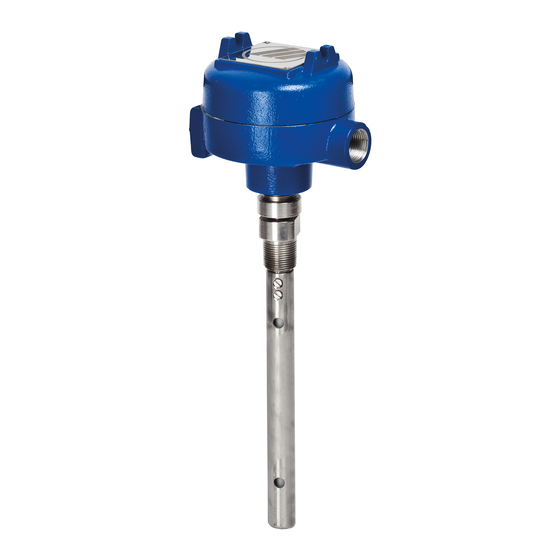
- Page 1 Kotron ® Series 82 CE Installation and Operating Manual Level Transmitter...
- Page 2 Conventions Used in this Manual International, Incorporated. Kotron Series 82 CE Certain conventions are used in this manual to convey RF Level Transmitter is a trade name of Magnetrol specific types of information. General technical material, International, Incorporated. support data, and safety information are presented in Copyright ©...
-
Page 3: Table Of Contents
Kotron Series 82 CE ® RF Level Transmitter Table of Contents 1.0 Complete Installation 2.0 Reference Information ..........14 1.1 Unpacking ............4 2.1 Description ............14 1.2 Electrostatic Discharge (ESD) Handling Procedure...4 2.2 Theory of Operation ...........14 1.3 Installation Location..........5 2.3 Troubleshooting...........14 1.4 Mounting ..............5 2.3.1 Installation..........14 1.4.1 Metal Walled Tanks ........5... -
Page 4: Complete Installation
• Record the model and serial numbers for future reference when ordering parts. Electrostatic Discharge (ESD) Handling Procedure Magnetrol ® electronic instruments are manufactured to the highest quality standards. These instruments use electronic components that may be damaged by static electricity pre- sent in most work environments. -
Page 5: Installation Location
Installation Location KOTRON RF Transmitters should be located for easy access for service, calibration and monitoring. Units should not be exposed to ambient temperatures below -40 °F (-40 °C) or above +160 °F (+70 °C). Special pre- caution should be made to prevent exposure to corrosive atmosphere, excessive vibration, shock or physical damage. -
Page 6: Non-Metallic And Glass-Lined Tank Construction
– 1. Connect the positive lead of the interconnection cable PROBE (supplied by MAGNETROL), to the screw terminal at the top of the probe. Connect the negative lead to the green 30-9012-001 ground screw at the base of the housing. Cut the shield;... -
Page 7: Flexible Probe
The end of a flexible probe MUST be kept taut by attaching the anchor end at the bottom of the vessel or by using a MAGNETROL supplied probe weight. Caution: Do not discard the Mylar housing insulator. -
Page 8: Integral Electronics
1.5.2.2 Remote Electronics 1. Connect the positive lead of the interconnection cable (supplied by MAGNETROL), to the screw terminal at the top of the probe. Connect the negative lead to the green ground screw at the base of the housing. Cut the shield;... -
Page 9: Wiring
Wiring The wiring directions are different depending upon the configuration of your particular transmitter. Choose the appropriate configuration from the following sections and follow the directions carefully. 1.6.1 Two-Wire Transmitter without Meter W RNING: These units are designed to operate with voltages between 14 VDC and 40 VDC only. -
Page 10: Four-Wire Transmitter Without Meter
3. Pull the power supply wires through the conduit connection. 4. Connect the positive supply wire to the (+) terminal and the negative supply wire to the (–) terminal. Connect Meter Transmitter the shield to the green ground screw at the base of the Power Supply Housing Terminals... -
Page 11: Four-Wire Transmitter With Meter
1.6.4 Four-Wire Transmitter with Meter Caution: All power must be turned off until all of the wiring connec- tions have been made. All wiring between the power supply and the transmitter should be done with 14 AWG to 18 AWG wire. The con- nection is made at the terminal strip, on the vertical board, within the transmitter enclosure. -
Page 12: Calibration
Calibration There are two calibration methods that can be used, depending on your particular situation. Calibration Procedure A will require moving the level from the 0% point (4 mA) to the 100% point (20 mA). Calibration Procedure B allows you to start at a level greater than 0% and stop at a level less than 100%. -
Page 13: Calibration Procedure B
7. If 20 mA cannot be reached, individually close Span Coarse DIP switches (in sequence), #1, #2, and #3, until the loop current is close to (and not less than), 20 mA. (ONLY ONE SWITCH POSITION SHOULD BE CLOSED AT A TIME—THE OTHER TWO POSITIONS MUST REMAIN OPEN). -
Page 14: Reference Information
Reference Information This section presents an overview of the operation of the KOTRON Series 82 CE RF Level Transmitter, information on troubleshooting common problems, intrinsic safety information, physical, functional and performance specifications, listings of agency approvals, and a list of recommended parts. Description KOTRON Series 82 CE Level Transmitters are designed to measure liquids, slurries, dry-bulk, or liquid-liquid inter-... -
Page 15: Calibration
c. Excessive loop resistance. Refer to chart on page 18 for maximum resistance. d. Power supply not turned on. e. Insufficient source voltage. 14 volts minimum is required at transmitter terminals. f. Test points jumpered together with current meter. Remove meter. g. -
Page 16: Operation
4. Span point cannot be increased to 20 mA at high level. a. Span controls incorrectly set — Turn span controls clockwise b. Insufficient probe capacitance — Increase span length or probe; — Increase probe diameter; — Locate probe closer to wall(s); —... - Page 17 2. Loop current randomly unstable. a. Disturbances in medium — Correct instability of medium b. Power supply unstable — Repair or replace power supply c. Electrical interference (RFI) — Consult factory. 3. Loop current exceeds 20 mA. a. Incorrect calibration —...
-
Page 18: Agency Approvals
5. Non-linear output a. Incorrect calibration — Recalibrate unit b. Excessive loop resistance. Loop Resistance vs. Power Supply Voltage — Reduce loop resistance 1300 1200 ohms @ 40 V 1200 c. Damaged jacket on insulated probe 1100 — Replace probe 1000 d. -
Page 19: Agency Specifications - Intrinsically Safe Installation
2.4.1 Agency Specifications – Intrinsically Safe Installation 50-613 Kotron ® Series 82 CE RF Level Transmitter... -
Page 20: Parts
Parts 2.5.1 Replacement Parts 2.5.1.1 Transmitter Item Description Part Number ➀ 4-20 mAdc Z30-9012-001 Potted Module 20-4 mAdc Z30-9012-002 ➁ Base 004-9104-001 ➂ Cover 004-9105-001 ➃ O-Ring 012-2101-345 Same as ➄ Probe Original Part Number ➅ Probe Wire 009-7176-001 ➆ Shielded Up to 20 ft. -
Page 21: Specifications
Specifications 2.6.1 Electrical Supply Voltage 24 VDC, (14-40 VDC) 120/240 VAC, 50-60 Hz, (+10/-15%) Current 38 mA maximum Line Variation Less than ± .10%/volt, for voltages between 16-40 VDC ➀ Ambient Temperature -40 to +160 °F (-40 to +70 °C) Zero Range 1000 pF (max.), 0pF (min.) Span Range... -
Page 22: Physical
2.6.2 Physical 4.63 (118) 12.65 (321) 4.63 (118) Dia. Dia. 3.00 (76) 3.00 (76) 2.75 (70) 3/4" NPT Optional 1" Optional mounting mounting flange 3.5" (90) flange 3.5" (90) 3/4" NPT 3/4" NPT I.L. I.L. .50 (13) .50 (13) .625 (16) .625 (16) Integral Mount with Rigid Probe Integral Mount with Rigid Probe and Meter... -
Page 23: Model Numbers
Model Numbers BASIC 82 CE transmitter HOUSING ⁄ " NPT dual conduit FUNCTION/INPUT POWER Four-wire, 120 VAC ➀ Four-wire, 240 VAC ➀ Two-wire, 24 VDC Nominal (14 to 40 VDC), FM, CSA Two-wire, 24 VDC Nominal (14 to 40 VDC), ATEX Intrinsically Safe OUTPUT SIGNAL Standard 4-20 mA MOUNTING CONFIGURATION... - Page 24 This is available Prepaid transportation. MAGNETROL will repair or through your MAGNETROL local representative or by replace the control at no cost to the purchaser (or owner) contacting the factory. Please supply the following infor-...
Need help?
Do you have a question about the 82 CE Series and is the answer not in the manual?
Questions and answers